RELEASABLE AND EXTENDABLE ZIPPER ATTACHMENT
US20140189984A1
2014-07-10
13/734,295
2013-01-04
Abstract:
The present technology includes both a process and a device for effecting the process. The process is a method of closing or opening access within a garment using the steps of:
-
- a) attaching a hooking element of a lockable pull device to a zipper on a garment;
- b) while a filament container of the lockable pull device is in an extended position from a housing of the lockable pull device within which the filament can be wound, activating a locking element to retain the filament in the extended position; and
- c) exerting directional force on the housing retaining the filament in the extended position while the hooking element is attached to the zipper to move the zipper to close or open access to the garment.
The device includes a lockable pull device for use in exerting force on a distal object such as a zipper.
Interested in similar patents?
Get notified when new applications in this technology area are published.
Classification:
A44B19/262 » CPC main
Slide fasteners; Details; Sliders Pull members; Ornamental attachments for sliders
A44B19/26 » CPC further
Slide fasteners; Details Sliders
A44B19/30 » CPC further
Slide fasteners; Details; Sliders with means for locking in position
Description
BACKGROUND OF THE ART
1. Field of the Invention
The present invention relates to the field of zippers on articles of clothing, and especially zippers on the rear of garments that can be difficult to grasp, and to attachments that may be used to grasp and pull zippers up or down.
2. Background of the Art
A zipper, zip, or zip fastener, is a commonly used device for temporarily joining two edges of fabric. It is used in clothing (e.g., dresses, jackets and jeans), luggage and other bags, sporting goods and other items.
The bulk of a zipper often consists of two strips of fabric tape, each affixed to one of the two pieces to be joined, carrying from tens to hundreds of specially shaped metal or plastic teeth. These teeth can be either individual or shaped from a continuous coil, and are also referred to as elements. The slider, operated by hand, moves along the rows of teeth. Inside the slider is a Y-shaped channel that meshes together or separates the opposing rows of teeth, depending on the direction of the slider's movement.
In many jackets and similar garments, the opening is closed entirely when the slider is at one of the ends of the tape. The mechanism allows for partial fastening where only some of the tape is fastened together, but various movements and pressures may move the slider around the tape. In many kinds of luggage, there are two sliders on the tape, mounted in opposite directions; the part of the zipper between them is unfastened. When the sliders are located at opposite ends of the tape, the zipper is fully unfastened; when the two sliders are located next to each other, which can be at any point along the tape, the zipper is fully closed.
Zippers may
-
- increase or decrease the size of an opening to allow or restrict the passage of objects, as in the fly of trousers or in a pocket.
- join or separate two ends or sides of a single garment, as in the front of a jacket, dress or skirt.
- attach or detach a separable part of the garment to or from another, as in the conversion between trousers and shorts or the connection/disconnection of a hood and a coat.
- decorate an item.
These variations are achieved by sewing one end of the zipper together, sewing both ends together, or allowing both ends of the zipper to fall completely apart.
A zipper costs relatively little, but if it fails, the garment may be unusable until the zipper is repaired or replaced—which can be quite difficult and expensive. Problems often lie with the zipper slider; when it becomes worn it does not properly align and join the alternating teeth. If a zipper fails, it can either jam (i.e. get stuck) or partially break off.
Gideon Sundback increased the number of fastening elements from four per inch (about one every 6.4 mm) to ten or eleven (around every 2.5 mm), introduced two facing rows of teeth that pulled into a single piece by the slider, and increased the opening for the teeth guided by the slider. The patent for the “Separable Fastener” was issued in 1917
There are a number of different styles and types of zippers.
-
- Coil zippers now form the bulk of sales of zippers worldwide. The slider runs on two coils on each side; the “teeth” are formed by the windings of the coils. Two basic types of coils are used: one with coils in spiral form, usually with a cord running inside the coils; the other with coils in ladder form. This second type is now used only in a few parts of the world, mainly in South Asia. Coil zippers are made of polyester coil and are thus also known as polyester zippers. Nylon was formerly used and though only polyester is used now, the type is still also known as a nylon zipper.
- Invisible zippers' have the teeth hidden behind a tape, so that the zipper is “invisible”. The tape's color matches the garment's, as does the slider's. This kind of a zipper is common in skirts and dresses. Invisible zippers are usually coil zippers.
- Metallic zippers are the classic zipper type, found mostly in jeans today. The teeth are not a coil, but are individual pieces of metal molded into shape and set on the zipper tape at regular intervals. Metal zippers are made in brass, aluminum and nickel, according to the metal used for teeth making. All these zippers are basically made from flat wire. A special type of metal zipper is made from pre-formed wire, usually brass but sometimes other metals too. This type of pre-formed metal zippers is mainly used in high grade jeans-wear, work-wear, etc., where high strength is required and zippers need to withstand tough washing.
- Plastic-molded zippers are identical to metallic zippers, except that the teeth are plastic instead of metal. Metal zippers can be painted to match the surrounding fabric; plastic zippers can be made in any color of plastic with dyes or pigments. Plastic zippers mostly use polyacetal resin, though other polymers are used as well, such as polyesters, nylon and polyolefins.
- Open-ended zippers use a “box and pin” mechanism to lock the two sides of the zipper into place, often in jackets. Open-ended zippers can be of any of the above specified types.
- Closed-ended zippers are closed at both ends; they are often used in luggage. A less common water-resistant zipper is similar in construction to a standard toothed zipper, but includes a molded plastic ridge seal similar to the mating surfaces on a plastic bag that closes when the slider moves and engages a male ridge and a female slot.
One of the difficulties in the use of zippers, especially in garments where the zipper runs up the back of the wearer is the difficulty in grasping a zipper at the top or bottom of the garment and sliding it to the other extreme. To provide minimal assistance in this regard, zipper “pulls” are often used which may extend the effective grasping length of the pull tab by the fixed length of the pull. These pulls usually attach through a hole in the end of the pull tab, which is common in many zipper constructions. Not only do these pulls provide a minimal length of extension, but when left on the zipper (even where they have a decorative design), can diminish the overall appearance of the garment, which in the case of designer clothes is very important to the wearer.
SUMMARY OF THE INVENTION
The present technology includes both a process and a device for effecting the process. The process is a method of closing or opening access within a garment using the steps of:
-
- a) attaching a hooking element of a lockable pull device to a zipper on a garment;
- b) while a filament container of the lockable pull device is in an extended position from a housing of the lockable pull device within which the filament can be wound, activating a locking element to retain the filament in the extended position; and
- c) exerting directional force on the housing retaining the filament in the extended position while the hooking element is attached to the zipper to move the zipper to close or open access to the garment.
The device includes a lockable pull device for use in exerting force on a distal object, the device having components of:
-
- a) a housing;
- b) the housing comprising two major opposed surfaces and a face connecting the two major opposed surfaces;
- c) a filament on a spool in which the filament may be wound onto the spool towards a proximal end of the filament and a distal end of the filament that may be unwound away from the spool;
- d) an opening on the face through which the distal end of the filament extends;
- e) the distal end of the filament having a hooking element thereon;
wherein at least one of the two major opposed faces or the face contains a pressure activated locking system that prevent the filament from being retracted or extended from the housing while pressure is maintained.
BRIEF DESCRIPTION OF THE FIGURES
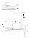
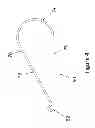
FIG. 1 shows a typical zipper according to the prior art.
FIG. 2 shows one embodiment of a locking element for use on the distal end of a filament according to the present technology.
FIG. 3 shows one second embodiment of a locking element for use on the distal end of a filament according to the present technology.
FIG. 4 shows one third embodiment of a locking element for use on the distal end of a filament according to the present technology.
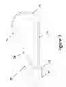
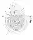
FIG. 5 shows a housing and pressure-activated locking element, with the filament extending from an opening in the face between two opposed surfaces of the housing.
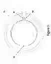
FIG. 6 shows an essentially open and empty housing with pressure-activated locking element.
DETAILED DESCRIPTION OF THE INVENTION
The present technology may be described as methods and devices, which in general terms may include any of the following. A method of closing or opening access within a garment which may include the steps of: a) attaching a hooking element of a lockable pull device to a zipper on a garment; b) while a filament container of the lockable pull device is in an extended position from a housing of the lockable pull device within which the filament can be wound, activating a locking element to retain the filament in the extended position; and c) exerting directional force on the housing retaining the filament in the extended position while the hooking element is attached to the zipper to move the zipper to close or open access to the garment. Activating the locking element may be done by manual pressure on a surface of the lockable pull device to engage an edge of a plate having a living hinge against the filament, or activating the locking element may be done by manual pressure on a button that passes through the housing to engage an internal end of the button with the filament to lock the filament. The method may be performed wherein after closing or opening a zipper, the hooking element is detached from the zipper (or left on the zipper) and the locking element is disengaged, and the filament is rewound into the lockable pull device.
An alternative description of this generic technology may include a lockable pull device for use in exerting force on a distal object, the device including, for example: a) a housing; b) the housing comprising two major opposed surfaces and a face connecting the two major opposed surfaces; c) a filament on a spool in which the filament may be wound onto the spool towards a proximal end of the filament and a distal end of the filament that may be unwound away from the spool; d) an opening on the face through which the distal end of the filament extends; e) the distal end of the filament having a hooking element thereon; wherein at least one of the two major opposed faces or the face contains a pressure activated locking system that prevent the filament from being retracted or extended from the housing while pressure is maintained. The device may include a flexible surface of the lockable pull device that can be depressed to engage the filament, such as where the locking element comprises a button that passes through the housing to engage an internal end of the button with the filament to lock the filament. The hooking element may be attached to a hole in the pull tab.
The present technology may reduce the strain and contortions and even damage to clothing during the opening and closing of zippers on clothing, especially on a rearward side of clothing that cannot be readily manipulated. For example, the device may be attached to the zipper through a hooking element (with filament extended or not), and when the filament is extended, the locking device is pressure activated, the housing manipulated into a convenient operation position (e.g., the device is raised over one shoulder, or an arm is extended over the shoulder, or the device (in an opening mode is dropped behind the back while grasping the device), the zipper is pulled to operate the zipper, and then the locking element is disengaged from the zipper pull tab. Upon release of pressure, a self-winding spool will withdraw the extended filament. In a manually spooled system, the filament would be wound into the housing by a handle or other device.
FIG. 1 shows a typical zipper system according to the prior art. The general components of a zipper in the prior art usually include, according to the components identified and shown in FIG. 1 as:
-
- 41. A top tape extension.
- 42. A top stop.
- 43. A slider.
- 44. A pull tab.
- 45. A tape.
- 46. The chain width.
- 47. A bottom stop.
- 48. A bottom tape extension.
- 49. A single tape width.
- 80. An insertion pin boll.
- 81. A slider retainer box.
- 82. Reinforcement edge, strip or film.
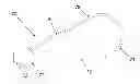
FIG. 2 shows one embodiment of a locking element 25 for use on the distal end of a filament 39 according to the present technology. The loop 34 that engages the zipper pull tab (not show) is shown with an expanded area 32. Within that expanded area 32 is shown a support area 35 of the loop 34 at the distal end of the filament 37. Also shown in the loop closing end 37 of the filament 39. The loop 34, the loop closing end 37 and the support area 35 should be sufficiently stiff as to allow tension by the loop closing end 37 to be supported by the loop without the loop opening. This may require that the loop 34, the loop closing end 37 and the support area 35 are composed of a material more rigid than the filament 39. For example, the filamentary material may be string, light cord, polymer, thread or the like, and the loop 34, the loop closing end 37 and the support area 35 may be metal, stiffer plastic, alloy, wood, composite or the like.
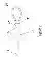
FIG. 3 shows one second embodiment of a locking element device 70 for use on the distal end of a filament according to the present technology. A slot 72 is provided for engaging the filament prior to use of the locking element device 70. The slot 72 is in a support box 73 for the loop 74. The loop 74 is shown with an opening in stiff material (as in FIG. 2) for the loop 74, the lower arm 75 and the locking short arm 76. Both the arms 75 and 76 are attached to the support box 73. The support box may be composed of any structural material such as be metal, plastic, alloy, wood, composite or the like.
FIG. 4 shows one third embodiment of a locking element 50 for use on the distal end of a filament according to the present technology. This device has similar elements similarly numbers as in FIG. 3. In this device, the support box 73 of FIG. 3 has been replaced by a simple filament attaching loop 52 through which the distal end of the filament (not shown) may be secured.
FIG. 5 shows a housing and pressure-activated locking element 2, with the filament 12 extending from an opening (98 in FIG. 6) in the housing 8 between two opposed surfaces (only one surface is shown, as the bottom surface is in the back side of this image) of the housing 8. The filament 12 is shown as a wound filament within the housing 8. A spring 10 is attached to a spool at 14 and to an axel 4, which is part of the rear housing. Pulling the filament 12 rotates the center housing 6 in relation to the fixed location of the front (95 FIG. 6) and rear 8 housing. The spring, being attached to the rear housing at 4 and to the rotating housing at 14, is wound. This loaded spring is then used to retract the filament 12 or may have a handle (not shown) extending out of the housing to allow the spool 6 to be wound. An axel 4 is centrally positioned within the housing 8 for the spool 6 to spin about is shown. An upper plate 95 on the top surface of the housing 8 is shown having a partially open circumference (90 in FIG. 6) about the surface so as to form a button with a living hinge that is not open, allowing the entire upper plate to flex and rotate downwardly, pressing tongue (92 in FIG. 6) against the filament 12 before it extends out of the opening 98 to lock the filament against further extension or withdrawal while pressure is maintained. In another embodiment of this figure, the button does not come into contact with the filament to stop the rotation. In this alternative, the small jutting out piece of plastic (92 on FIG. 6) can be pushed down into a slot cut into the rotating spool (6 on FIG. 5). This allows for a slight pressure to the button to prevent the spool from rotating. A top view of the housing 95 is shown in FIG. 6. Element 16 is a grip and blocker that prevents the filament 12 from being completely withdrawn into the housing 8. This dual function element allows for easy gripping by fingers of the filament while not allowing the filament to become inaccessible by withdrawal into the housing. The element 16 may be a polymeric, metal, composition or natural (e.g., wood or rubber) material.
The button does not have to actually contact the filament, but may press an intermediate panel or plate (not shown) against the filament, or torque the faces or axel out of alignment to provide resistance against the filament to prevent its retraction.
Claims
What is claimed:1. A method of closing or opening access within a garment comprising the steps of:
a) attaching a hooking element of a lockable pull device to a zipper on a garment;
b) while a filament container of the lockable pull device is in an extended position from a housing of the lockable pull device within which the filament can be wound, activating a locking element to retain the filament in the extended position; and
c) exerting directional force on the housing retaining the filament in the extended position while the hooking element is attached to the zipper to move the zipper to close or open access to the garment.
2. The method of claim 1 wherein activating the locking element is done by manual pressure on a surface of the lockable pull device to engage an edge of a plate having a living hinge against the filament.
3. The method of claim 1 wherein activating the locking element is done by manual pressure on a button that passes through the housing to engage an internal end of the button with the filament to lock the filament.
4. The method of claim 1 wherein after closing or opening a zipper, the hooking element is detached from the zipper and the locking element is disengaged, and the filament is rewound into the lockable pull device.
5. A lockable pull device for use in exerting force on a distal object, the device comprising:
a) a housing;
b) the housing comprising two major opposed surfaces and a face connecting the two major opposed surfaces;
c) a filament on a spool in which the filament may be wound onto the spool towards a proximal end of the filament and a distal end of the filament that may be unwound away from the spool;
d) an opening on the face through which the distal end of the filament extends;
e) the distal end of the filament having a hooking element thereon;
wherein at least one of the two major opposed faces or the face contains a pressure activated locking system that prevent the filament from being retracted or extended from the housing while pressure is maintained.
6. The device of claim 5 wherein the locking element comprises a flexible surface of the lockable pull device that can be depressed to engage the filament.
7. The device of claim 5 wherein the locking element comprises a button that passes through the housing to engage an internal end of the button with the filament to lock the filament.
8. The device of claim 5 wherein the hooking element is attached to a hole in the pull tab.
9. The device of claim 6 wherein the hooking element is attached to a hole in the pull tab.
10. The device of claim 7 wherein the hooking element is attached to a hole in the pull tab.
11. The device of claim 5 wherein a gripping element is attached to the filament outside the housing to prevent the filament from being completely withdrawn into the housing.
12. The device of claim 6 wherein a gripping element is attached to the filament outside the housing to prevent the filament from being completely withdrawn into the housing.
13. The device of claim 7 wherein a gripping element is attached to the filament outside the housing to prevent the filament from being completely withdrawn into the housing.
14. The device of claim 8 wherein a gripping element is attached to the filament outside the housing to prevent the filament from being completely withdrawn into the housing.
Images & Drawings included:
Sources:
- United States Patent and Trademark Office - verify current appl. status at the USPTO↗
Recent applications in this class:
- » 20250120481 2025-04-17
SLIDER - » 20240398071 2024-12-05
Pocket zipper connecting system - » 20240381981 2024-11-21
Custom Zipper Pull - » 20240373993 2024-11-14
SLIDER CAPABLE OF MINIMIZING SCRATCHING ON ZIPPER, ZIPPER USING THE SLIDER, AND COMMERCIAL PRODUCT USING THE ZIPPER - » 20240324733 2024-10-03
CORD LOCK, WEBBING CLIP, WEBBING HARDWARE OR ZIPPER PULL INCLUDING TRITIUM - » 20240315402 2024-09-26
Slider for a slide fastener - » 20240298756 2024-09-12
Replacement Puller Handle Adapted to be Attach-ably Retained on the Slider Fastener of a Zipper - » 20240285041 2024-08-29
ACCESSIBLE ZIPPER PULL - » 20240122308 2024-04-18
Zipper Assist Device - » 20240115014 2024-04-11
Decoration Receiving Element, Slider and Decoration Receiving Element, and Hidden Slide Fastener