Method and device for generating two purified partial air streams
US20140223960A1
2014-08-14
14/345,717
2012-09-20
✅ Patent granted
US 10,222,120 B2
2019-03-05
WO; PCT/EP2012/003945; 20120920
WO; WO2013/053425; 20130418
Keith Raymond
Millen White Zelano & Branigan, PC
2035-02-01
Abstract:
The invention relates to a method and device for generating two purified partial air streams under different pressures. A total air stream (1) is compressed to a first total air pressure. The compressed total air stream (5) is cooled with cooling water under the first total air pressure by way of heat exchange (4, 6). The heat exchange with cooling water for cooling the total air stream (5) is carried out as a direct heat exchange in a first direct contact cooler (6), at least in part. The cooled total air stream (9) is divided into a first partial air stream (10) and a second partial air stream (11). The first partial air stream (10) is purified in a first purification device (18) under the first total air pressure, generating the first purified partial air stream (19). The second partial air stream (11) is re-compressed to a higher pressure (12), which is higher than the first total air pressure. The re-compressed second partial air stream (14) is cooled with cooling water in a second direct contact cooler (15) by way of direct heat exchange (13, 15). The cooled second partial air stream (17) is purified under the higher pressure in a second purification device (30), thus generating the second purified partial air stream (31).
Inventors:
- Alexander Alekseev 36 🇩🇪 Wolfratshausen, Germany
- Dimitri GOLOUBEV 8 🇩🇪 Munchen, Germany
- Dimitri Goloubev 11 🇩🇪 Munich, Germany
Assignee:
- LINDE AKTIENGESELLSCHAFT 160 🇩🇪 Munchen, Germany
- Linde Aktiengesellschaft 400 🇩🇪 Munich, Germany
Applicant:
Interested in similar patents?
Get notified when new applications in this technology area are published.
Classification:
F25J3/04309 » CPC further
Processes or apparatus for separating the constituents of gaseous or liquefied gaseous mixtures involving the use of liquefaction or solidification by rectification, i.e. by continuous interchange of heat and material between a vapour stream and a liquid stream for air; Generation of cold for compensating heat leaks or liquid production, e.g. by Joule-Thompson expansion using internal refrigeration by open-loop gas work expansion, e.g. of intermediate or oxygen enriched (waste-)streams of nitrogen
F25J3/04878 » CPC further
Processes or apparatus for separating the constituents of gaseous or liquefied gaseous mixtures involving the use of liquefaction or solidification by rectification, i.e. by continuous interchange of heat and material between a vapour stream and a liquid stream for air; Start-up or control of the process; Details of the apparatus used; Construction and layout of air fractionation equipments, e.g. valves, machines; Vertical layout of cold equipments within in the cold box, e.g. columns, heat exchangers etc. Side by side arrangement of multiple vessels in a main column system, wherein the vessels are normally mounted one upon the other or forming different sections of the same column
F25J2250/50 » CPC further
Details related to the use of reboiler-condensers; External or auxiliary boiler-condenser in general, e.g. without a specified fluid or one fluid is not a primary air component or an intermediate fluid One fluid being oxygen
F25J3/04 » CPC main
Processes or apparatus for separating the constituents of gaseous or liquefied gaseous mixtures involving the use of liquefaction or solidification by rectification, i.e. by continuous interchange of heat and material between a vapour stream and a liquid stream for air
F25J3/0409 » CPC further
Processes or apparatus for separating the constituents of gaseous or liquefied gaseous mixtures involving the use of liquefaction or solidification by rectification, i.e. by continuous interchange of heat and material between a vapour stream and a liquid stream for air; Providing pressurised feed air or process streams within or from the air fractionation unit providing pressurized products by liquid compression and vaporisation with cold recovery, i.e. so-called internal compression of oxygen
F25J3/04018 » CPC further
Processes or apparatus for separating the constituents of gaseous or liquefied gaseous mixtures involving the use of liquefaction or solidification by rectification, i.e. by continuous interchange of heat and material between a vapour stream and a liquid stream for air; Providing pressurised feed air or process streams within or from the air fractionation unit by compression of warm gaseous streams; details of intake or interstage cooling of main feed air
F25J3/0486 » CPC further
Processes or apparatus for separating the constituents of gaseous or liquefied gaseous mixtures involving the use of liquefaction or solidification by rectification, i.e. by continuous interchange of heat and material between a vapour stream and a liquid stream for air; Start-up or control of the process; Details of the apparatus used; Operation, control and regulation of the process; Instrumentation within the process; Safety aspects of operation of vaporisers for oxygen enriched liquids, e.g. purging of liquids
F25J3/04157 » CPC further
Processes or apparatus for separating the constituents of gaseous or liquefied gaseous mixtures involving the use of liquefaction or solidification by rectification, i.e. by continuous interchange of heat and material between a vapour stream and a liquid stream for air; Purification and (pre-)cooling of the feed air; recuperative heat-exchange with product streams Afterstage cooling and so-called "pre-cooling" of the feed air upstream the air purification unit and main heat exchange line
F25J3/04169 » CPC further
Processes or apparatus for separating the constituents of gaseous or liquefied gaseous mixtures involving the use of liquefaction or solidification by rectification, i.e. by continuous interchange of heat and material between a vapour stream and a liquid stream for air; Purification and (pre-)cooling of the feed air; recuperative heat-exchange with product streams; Hot end purification of the feed air by adsorption of the impurities
F25J3/04181 » CPC further
Processes or apparatus for separating the constituents of gaseous or liquefied gaseous mixtures involving the use of liquefaction or solidification by rectification, i.e. by continuous interchange of heat and material between a vapour stream and a liquid stream for air; Purification and (pre-)cooling of the feed air; recuperative heat-exchange with product streams; Hot end purification of the feed air by adsorption of the impurities Regenerating the adsorbents
F25J3/04206 » CPC further
Processes or apparatus for separating the constituents of gaseous or liquefied gaseous mixtures involving the use of liquefaction or solidification by rectification, i.e. by continuous interchange of heat and material between a vapour stream and a liquid stream for air; Purification and (pre-)cooling of the feed air; recuperative heat-exchange with product streams; Cooling of the purified feed air by recuperative heat-exchange; Heat-exchange with product streams; Division of the main heat exchange line in consecutive sections having different functions including a so-called "auxiliary vaporiser" for vaporising and producing a gaseous product
F25J3/04218 » CPC further
Processes or apparatus for separating the constituents of gaseous or liquefied gaseous mixtures involving the use of liquefaction or solidification by rectification, i.e. by continuous interchange of heat and material between a vapour stream and a liquid stream for air; Purification and (pre-)cooling of the feed air; recuperative heat-exchange with product streams; Cooling of the purified feed air by recuperative heat-exchange; Heat-exchange with product streams Parallel arrangement of the main heat exchange line in cores having different functions, e.g. in low pressure and high pressure cores
F25J3/04303 » CPC further
Processes or apparatus for separating the constituents of gaseous or liquefied gaseous mixtures involving the use of liquefaction or solidification by rectification, i.e. by continuous interchange of heat and material between a vapour stream and a liquid stream for air; Generation of cold for compensating heat leaks or liquid production, e.g. by Joule-Thompson expansion using internal refrigeration by open-loop gas work expansion, e.g. of intermediate or oxygen enriched (waste-)streams of feed air, e.g. used as waste or product air or expanded into an auxiliary column Lachmann expansion, i.e. expanded into oxygen producing or low pressure column
F25J3/04448 » CPC further
Processes or apparatus for separating the constituents of gaseous or liquefied gaseous mixtures involving the use of liquefaction or solidification by rectification, i.e. by continuous interchange of heat and material between a vapour stream and a liquid stream for air using at least a triple pressure main column system in a double column flowsheet with an intermediate pressure column
F25J3/04884 » CPC further
Processes or apparatus for separating the constituents of gaseous or liquefied gaseous mixtures involving the use of liquefaction or solidification by rectification, i.e. by continuous interchange of heat and material between a vapour stream and a liquid stream for air; Start-up or control of the process; Details of the apparatus used; Construction and layout of air fractionation equipments, e.g. valves, machines; Vertical layout of cold equipments within in the cold box, e.g. columns, heat exchangers etc. Arrangement of reboiler-condensers
F25J3/04957 » CPC further
Processes or apparatus for separating the constituents of gaseous or liquefied gaseous mixtures involving the use of liquefaction or solidification by rectification, i.e. by continuous interchange of heat and material between a vapour stream and a liquid stream for air; Start-up or control of the process; Details of the apparatus used; Construction and layout of air fractionation equipments, e.g. valves, machines; Arrangements of multiple air fractionation units or multiple equipments fulfilling the same process step, e.g. multiple trains in a network and inter-connecting equipments upstream of the fractionation unit (s), i.e. at the "front-end"
F25J2200/54 » CPC further
Processes or apparatus using separation by rectification using multiple (re-)boiler-condensers at different heights of the column in the low pressure column of a double pressure main column system
F25J2205/32 » CPC further
Processes or apparatus using other separation and/or other processing means using a washing, e.g. "scrubbing" or bubble column for purification purposes as direct contact cooling tower to produce a cooled gas stream, e.g. direct contact after cooler [DCAC]
F25J2205/34 » CPC further
Processes or apparatus using other separation and/or other processing means using a washing, e.g. "scrubbing" or bubble column for purification purposes as evaporative cooling tower to produce chilled water, e.g. evaporative water chiller [EWC]
F25J2205/62 » CPC further
Processes or apparatus using other separation and/or other processing means using adsorption on solid adsorbents, e.g. by temperature-swing adsorption [TSA] at the hot or cold end Purifying more than one feed stream in multiple adsorption vessels, e.g. for two feed streams at different pressures
F25J2210/06 » CPC further
Processes characterised by the type or other details of the feed stream Splitting of the feed stream, e.g. for treating or cooling in different ways
F25J2230/04 » CPC further
Processes or apparatus involving steps for increasing the pressure of gaseous process streams Compressor cooling arrangement, e.g. inter- or after-stage cooling or condensate removal
F25J2230/40 » CPC further
Processes or apparatus involving steps for increasing the pressure of gaseous process streams the fluid being air
F25J2235/52 » CPC further
Processes or apparatus involving steps for increasing the pressure or for conveying of liquid process streams the fluid being oxygen enriched compared to air ("crude oxygen")
F25J2250/04 » CPC further
Details related to the use of reboiler-condensers Down-flowing type boiler-condenser, i.e. with evaporation of a falling liquid film
F25J2250/40 » CPC further
Details related to the use of reboiler-condensers; External or auxiliary boiler-condenser in general, e.g. without a specified fluid or one fluid is not a primary air component or an intermediate fluid One fluid being air
F25J3/00 IPC
Processes or apparatus for separating the constituents of gaseous or liquefied gaseous mixtures involving the use of liquefaction or solidification
Description
The invention relates to a method for generating two purified air substreams at different pressures.
A “condenser-evaporator” denotes a heat exchanger in which a first condensing fluid stream comes into indirect heat exchange with a second evaporating fluid stream. Each condenser-evaporator has a liquefaction chamber and an evaporation chamber which consist of liquefaction passages or evaporation passages, respectively. In the liquefaction chamber, a first fluid stream is condensed (liquefied) and in the evaporation chamber, a second fluid stream is evaporated. Evaporation and liquefaction chambers are formed by groups of passages which are in a heat-exchange relationship with one another.
A condenser-evaporator can be constructed, for example, as a falling-film or bath evaporator. In a “falling-film evaporator”, the film that is to be evaporated flows from top to bottom through the evaporation chamber and is partially evaporated in the course of this. In a “bath evaporator” (sometimes also termed “circulation evaporator” or “thermosiphon evaporator”) the heat-exchanger block is in a liquid bath of the fluid that is to be evaporated. This flows owing to the thermosiphon effect from bottom to top through the evaporation passages and exits again at the top as a two-phase mixture. The remaining liquid flows outside the heat-exchanger block back into the liquid bath (in a bath evaporator, the evaporation chamber can comprise not only the evaporation passages but also the outer chamber around the heat-exchanger block).
The condenser-evaporator for the low-pressure column (the low-pressure column intermediate evaporator and the low-pressure column sump evaporator) can be arranged in the interior of the low-pressure column or in one or more separate containers.
EP 342436 A2 discloses compressing a total air stream (1) to a first total air pressure, dividing into two air substreams, boosting one of these and purifying the two air substreams in two purification appliances which are operated at different pressures for the compression.
The object of the invention is to design such a method and a corresponding device in such a manner that they are energetically particularly expedient to operate.
This object is achieved by the features of claim 1.
In the invention, the total air stream, before division thereof, is cooled by direct heat exchange with cooling water in the first direct contact cooler to a particularly low temperature which is, in particular, below the ambient temperature. Using conventional aftercoolers or intercoolers, such a low temperature cannot usually be achieved. At this particularly low temperature, the second air substream then enters the boosting. The corresponding volume reduction at the intake of the recompressor effects a noticeable improvement of the efficiency of the boosting and thereby saves energy.
Upstream of the first direct contact cooler, a conventional aftercooler can be connected, in which the total air stream, after the compression thereof to the first total air pressure, is cooled by indirect heat exchange with cooling water to a temperature which is generally higher than the ambient temperature. The cooling of the total air between compression and division to the two air substreams can, however, also be performed solely in the first direct contact cooler.
The heat exchange with cooling water for cooling the boosted second air substream (14) could alternatively in principle proceed indirectly. In the invention, this cooling, however, is carried out at least in part as direct heat exchange in a second direct contact cooler. Upstream of the second direct contact cooler, a conventional aftercooler can be connected, in which the boosted second air substream is cooled by indirect heat exchange with cooling water to a temperature which is generally higher than the ambient temperature. However, the cooling can alternatively be performed solely in the direct contact cooler.
All compression steps can be accomplished in a multistage manner and then each have preferably one conventional intercooling between each pair of successively following stages.
The invention further relates to the use of the above method for providing feed air at two different pressure levels for a low-temperature fractionation of air as claimed in claim 3.
The invention further relates to a device as claimed in claim 4. The device according to the invention can be supplemented by device features which correspond to the features of the dependent method claims.
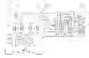
The invention and further details of the invention will be described in more detail hereinafter with reference to an exemplary embodiment shown schematically in FIG. 1.
Atmospheric air 1 is drawn in by suction in FIG. 1 via a filter 2 by a main air compressor 3 with aftercooler 4 and there compressed to a first total air pressure of 3.1 bar. The main air compressor can have two or more stages with intercooling; for reasons of redundancy it is preferably constructed in two lines (both are not shown in the drawing). The total air stream 5 is fed at the first total air pressure and a temperature of 295 K to a first direct contact cooler 6 and there further cooled to 283 K in direct heat exchange with cooling water 7 from an evaporative cooler 8. The cooled total air stream 9 is divided into a first air substream 10 and a second air substream 11.
The second air substream 11 is compressed in a booster 12 with aftercooler 13 from the first total air pressure (minus pressure drops) to a second total air pressure of 4.9 bar. The booster can have two or more stages with intercooling; for reasons of redundancy it is preferably constructed in two lines (both are not shown in the drawing). Each line of the main air compressor and the booster can be constructed as one machine having a shared drive, in particular as a geared compressor. The second air substream 14 is then cooled from 295 K to 290 K in a second direct contact cooler 15, more precisely in direct heat exchange with a warmer cooling water stream 16.
The first air substream is purified in a first purification appliance 18 which is operated at the first total air pressure, and then passed via line 19 at this pressure to the warm end of a main heat exchanger, which in the exemplary embodiment is formed by two blocks 20, 21 connected in parallel. The air cooled to about dew point forms a “first feed air stream”, which is fed to a first high-pressure column 23.
The first high-pressure column 23 is part of a distillation column system for nitrogen-oxygen separation which, in addition, has a second high-pressure column 24, a low-pressure column consisting of two sections 25, 26, a low-pressure column intermediate evaporator 27, a low-pressure column sump evaporator 28 and an auxiliary condenser 29. The low-pressure column intermediate evaporator 27 and the low-pressure column sump evaporator 28 are constructed as falling-film evaporators, and the auxiliary condenser 29 as a bath evaporator.
The precooled second air substream 17 is purified in a second purification appliance 30 which is operated at the second total air pressure. From the purified second air substream, via line 32, a small part can be withdrawn which is used as instrument air or for purposes outside the air fractionation. The remainder flows via line 33 to the main heat exchanger 20 and is there cooled. The cooled second air substream 34 is divided into a “second feed air stream” 35 which is introduced into the second high-pressure column 24, and into a “third feed air stream” 36, which is passed to the liquefaction chamber of the auxiliary condenser 29.
The at least partially, preferably substantially completely, condensed third substream 37 is introduced into a separator (phase separator) 38. The liquid fraction 39 is fed in a first part 40 to the first high-pressure column 23. In a second part 41, it is fed via a subcooling countercurrent heat exchanger 42 and line 43 into the low-pressure column 26.
Nitrogen-rich overhead gas 44 of the first high-pressure column 23 is condensed in a first part in the low-pressure column intermediate evaporator 27. Here, liquid nitrogen 46 that is obtained is applied in a first part 47 as reflux to the top of the first high-pressure column 23. A second part 48 is cooled in the subcooling countercurrent heat exchanger 42 and applied via line 49 as reflux to the top of the low-pressure column 26. A part 50 of the subcooled liquid can if required be obtained as liquid product (LIN).
A second part 51 of the nitrogen-rich overhead gas 44 of the first high-pressure column 23 is introduced into the main heat exchanger 20. At least a part 52 thereof is only warmed to an intermediate temperature and is then work-producingly expanded in a generator-braked compressed nitrogen turbine 53 from 2.7 bar to 1.25 bar. The outlet pressure of the turbine is already sufficient to force the work-producingly expanded stream 54 through the main heat exchanger 20 and via the lines 55, 56, 57 as regeneration gas through the first and the second purification appliances 18, 30.
A further part of the stream 51 is warmed to ambient temperature in the main heat exchanger 20 and obtained as gaseous pressurized nitrogen product (PGAN).
Nitrogen-rich overhead gas 58 of the second high-pressure column 24 is condensed in the low-pressure column sump evaporator 28. In this process, liquid nitrogen 59 that is obtained is applied in a first part 60 as reflux to the top of the second high-pressure column 24. A second part 61 is cooled in the subcooling countercurrent heat exchanger 42 and applied via line 62 as reflux to the top of the low-pressure column 26.
The sump liquids 63, 64 of the two high-pressure columns 23, 24 are combined, and fed via line 65, the subcooling countercurrent heat exchanger 42 and line 66 to the low-pressure column 26.
The sump liquid 66 of the low-pressure column 25 is introduced into the evaporation chamber of the low-pressure column sump evaporator 28 and there in part evaporated. The fraction 67 remaining liquid flows into the evaporation chamber of the auxiliary condenser 29 and is there in part evaporated. The evaporated fraction 68 is passed to the cold end of the main heat exchanger block 20, warmed to about ambient temperature and finally, via line 69, obtained as gaseous oxygen product (GOX) of a purity of 95 mol %. The fraction remaining liquid is, as a part 70, in a pump 71, evaporated and warmed to a pressure of 6 bar in the main heat exchanger block 21 and finally admixed to the gaseous oxygen product 69. Another part 72 can be obtained as liquid oxygen product (LOX) via the subcooling countercurrent heat exchanger 42, pump 73 and line 74.
A liquid intermediate fraction 75 which occurs at the bottom end of the second low-pressure column section 26 is transported by means of a pump 76 into the evaporation chamber of the low-pressure column intermediate evaporator 27 and there in part evaporated. Steam generated in this process is passed together with steam produced at the top of the first low-pressure column section 25, via the lines 77 and 79 to the second low-pressure column section 26, optionally together with circulating purge liquid 78. The remainder of the intermediate fraction remaining liquid serves as reflux liquid in the first low-pressure column section 25.
At the top of the low-pressure column 26, nitrogen-rich residual gas 80 is taken off at a pressure of 1.26 bar and, after warming in the subcooling countercurrent heat exchanger 42 and main heat exchanger 20 is fed via line 81 virtually unpressurized as dry gas into the evaporative cooler 8 and there utilized for cooling down cooling water 82.
Claims
1. A method for generating two purified air substreams at different pressures, in which
a total air stream (1) is compressed to a first total air pressure,
the compressed total air stream (5) is cooled at the first total air pressure by heat exchange (4, 6) with cooling water,
the heat exchange with cooling water for cooling the total air stream (5) is carried out at least in part as direct heat exchange in a first direct contact cooler (6),
the cooled total air stream (9) is divided into a first air substream (10) and a second air substream (11),
the first air substream (10) is purified at the first total air pressure in a first purification appliance (18) and obtained as a first purified air substream (19),
the second air substream (11) is boosted (12) to a higher pressure which is higher than the first total air pressure,
the boosted second air substream (14) is cooled by heat exchange (13, 15) with cooling water,
the heat exchange with cooling water for cooling the boosted second air substream (14) is carried out at least in part as direct heat exchange in a second direct contact cooler (15),
the cooled second air substream (17) is purified at the higher pressure in a second purification appliance (30) and obtained as a second purified air substream (31).
2. The method as claimed in claim 1, characterized in that the total air stream (5) is cooled in the first direct contact cooler (6) to a low temperature which is below the ambient temperature.
3. A method for the low-temperature fractionation of air in a distillation column system for nitrogen-oxygen separation, in which a first purified air sub stream and a second purified air sub stream as claimed in claim 1 are generated and at least a part of the first purified air substream and at least a part of the second purified air substream are introduced into the distillation column system for nitrogen-oxygen separation.
4. A device for generating two purified air substreams at different pressures, having
a main air compressor for compressing a total air stream (1) to a first total air pressure,
a first direct contact cooler (6) for cooling the compressed total air stream (5) at the first total air pressure by direct heat exchange (4, 6) with cooling water,
means for dividing the total air stream (9) cooled in the first direct contact cooler into a first air substream (10) and a second air substream (11),
a first purification appliance (18) for purifying the first air substream (10) at the first total air pressure,
means for obtaining the first air substream as a first purified air substream stream (19) downstream of the first purification appliance (18),
a booster (12) for boosting the second air substream (11) to a higher pressure which is higher than the first total air pressure,
a second direct contact cooler (15) for cooling the boosted second air substream (14) by direct heat exchange (4, 6) with cooling water,
a second purification appliance (30) for purifying the cooled second air substream (17) at the higher pressure and having
means for obtaining the second air substream as a second purified air substream stream (31) downstream of the second purification appliance (30).
Images & Drawings included:
Sources:
- United States Patent and Trademark Office - verify current appl. status at the USPTO↗
Recent applications in this class:
- » 20150211789 2015-07-30
Condenser-reboiler system and method - » 20140360227 2014-12-11
Method For Producing One Or More Air Separation Apparatuses, And Equipment For Air Separation By Cryogenic Distillation - » 20140345106 2014-11-27
Method for installing a condenser in a remote manufacturing yard - » 20140318179 2014-10-30
Process And Apparatus For The Separation Of Air By Cryogenic Distillation - » 20140283550 2014-09-25
METHOD AND INSTALLATION FOR SEPARATING AIR BY CRYOGENIC DISTILLATION - » 20140260422 2014-09-18
Low temperature air separation process for producing pressurized gaseous product - » 20140230486 2014-08-21
Method and device for recovering high-pressure oxygen and high-pressure nitrogen - » 20140223959 2014-08-14
Method and device for the cryogenic decomposition of air - » 20140216105 2014-08-07
Hybrid apparatus for drying a flow of compressed gas - » 20140174123 2014-06-26
Air separation method and apparatus
Recent applications for this Assignee:
- » 20220025246 2022-01-27
Hydrocarbon based carrier fluid - » 20210331956 2021-10-28
METHODS FOR WASTEWATER TREATMENT - » 20210284589 2021-09-16
Method for producing a separation product containing predominantly hydrocarbons with two carbon atoms - » 20210284589 2021-09-16
Method for producing a separation product containing predominantly hydrocarbons with two carbon atoms - » 20210130264 2021-05-06
Method and system for obtaining one or more olefins - » 20200338515 2020-10-29
Method and system for forming and for catalytically reacting a reactant mixture—embodiment of the reactor - » 20200318912 2020-10-08
Controllable liquid distributor of a coiled-tube heat exchanger for realizing different liquid loadings - » 20200309327 2020-10-01
Method for operating an industrial plant with an adsorption device and industrial plant with an adsorption device - » 20200309327 2020-10-01
Method for operating an industrial plant with an adsorption device and industrial plant with an adsorption device - » 20200298191 2020-09-24
VOLUMETRIC AND GRAVIMETRIC FILL LEVEL FOR PRODUCING A GAS MIXTURE