Circuit for the inductive heating of a metal
US20140361007A1
2014-12-11
14/372,557
2013-01-15
✅ Patent granted
US 10,165,628 B2
2018-12-25
WO; PCT/AT2013/050010; 20130115
WO; WO2013/106877; 20130725
Michael G Hoang
Collard & Roe, P.C.
2035-08-22
Abstract:
The invention relates to a circuit for the inductive heating of a metal that is optionally embedded in a non-magnetic bed by means of a transformer. The transformer induces eddy currents in the metal as a function of an exciter current IL and an exciter voltage UL and forms a load impedance XL together with the metal to be heated. Moreover, temperature monitoring is provided for the metal to be heated. In order to provide advantageous monitoring conditions it is proposed that the load impedance XL is preferably operated in the region of the resonant frequency thereof, the exciter current IL and exciter voltage UL and their phase shift Δφ relative to each other are measured and logged when the metal is heated, and a temperature progression which is proportional to the phase shift Δφ is calculated from the exciter current IL, exciter voltage UL and phase shift Δφ.
Assignee:
- KE KELIT KUNSTSTOFFWERK GESELLSCHAFT M.B.H. 4 🇦🇹 Linz, Austria
Applicant:
Interested in similar patents?
Get notified when new applications in this technology area are published.
Classification:
B29C66/91221 » CPC further
General aspects of processes or apparatus for joining preformed parts; Measuring or controlling the joining process by measuring or controlling the temperature, the heat or the thermal flux by measuring the temperature, the heat or the thermal flux by measuring the temperature of the parts to be joined
B29C65/36 » CPC further
Joining of preformed parts ; Apparatus therefor by heating, with or without pressure using heated elements which remain in the joint, e.g. "verlorenes Schweisselement" heated by induction
B29C65/3644 » CPC further
Joining of preformed parts ; Apparatus therefor by heating, with or without pressure using heated elements which remain in the joint, e.g. "verlorenes Schweisselement" heated by induction characterised by the type of elements heated by induction which remain in the joint being a ribbon, band or strip
B29C66/522 » CPC further
General aspects of processes or apparatus for joining preformed parts; General aspects of joining tubular articles; General aspects of joining long products, i.e. bars or profiled elements; General aspects of joining single elements to tubular articles, hollow articles or bars; General aspects of joining several hollow-preforms to form hollow or tubular articles; Joining tubular articles, profiled elements or bars; Joining single elements to tubular articles, hollow articles or bars; Joining several hollow-preforms to form hollow or tubular articles; Joining tubular articles, bars or profiled elements Joining tubular articles
B29C66/73921 » CPC further
General aspects of processes or apparatus for joining preformed parts characterised by the composition, physical properties or the structure of the material of the parts to be joined; Joining with non-plastics material characterised by the intensive physical properties of the material of the parts to be joined, by the optical properties of the material of the parts to be joined, by the extensive physical properties of the parts to be joined, by the state of the material of the parts to be joined or by the material of the parts to be joined being a thermoplastic or a thermoset characterised by the material of the parts to be joined being a thermoplastic or a thermoset characterised by the material of at least one of the parts being a thermoplastic characterised by the materials of both parts being thermoplastics
B29C66/9192 » CPC further
General aspects of processes or apparatus for joining preformed parts; Measuring or controlling the joining process by measuring or controlling the temperature, the heat or the thermal flux characterised by specific temperature, heat or thermal flux values or ranges in explicit relation to another variable, e.g. temperature diagrams
B29C66/91214 » CPC further
General aspects of processes or apparatus for joining preformed parts; Measuring or controlling the joining process by measuring or controlling the temperature, the heat or the thermal flux by measuring the temperature, the heat or the thermal flux by measuring the temperature with special temperature measurement means or methods by measuring the electrical resistance of a resistive element belonging to one of the parts to be welded, said element acting, e.g. as a thermistor
B29C66/91216 » CPC further
General aspects of processes or apparatus for joining preformed parts; Measuring or controlling the joining process by measuring or controlling the temperature, the heat or the thermal flux by measuring the temperature, the heat or the thermal flux by measuring the temperature with special temperature measurement means or methods enabling contactless temperature measurements, e.g. using a pyrometer
B29C66/91443 » CPC further
General aspects of processes or apparatus for joining preformed parts; Measuring or controlling the joining process by measuring or controlling the temperature, the heat or the thermal flux by controlling or regulating the temperature, the heat or the thermal flux by controlling or regulating the temperature the temperature being non-constant over time following a temperature-time profile
B29C66/91651 » CPC further
General aspects of processes or apparatus for joining preformed parts; Measuring or controlling the joining process by measuring or controlling the temperature, the heat or the thermal flux by controlling or regulating the temperature, the heat or the thermal flux by controlling or regulating the heat or the thermal flux, i.e. the heat flux by controlling or regulating the heat generated by Joule heating or induction heating
B29C66/91951 » CPC further
General aspects of processes or apparatus for joining preformed parts; Measuring or controlling the joining process by measuring or controlling the temperature, the heat or the thermal flux characterised by specific temperature, heat or thermal flux values or ranges in explicit relation to another variable, e.g. temperature diagrams in explicit relation to time, e.g. temperature-time diagrams
B29C66/963 » CPC further
General aspects of processes or apparatus for joining preformed parts; Measuring or controlling the joining process characterised by the method for implementing the controlling of the joining process using stored or historical data sets, e.g. using expert systems
G01K7/32 » CPC further
Measuring temperature based on the use of electric or magnetic elements directly sensitive to heat ; Power supply therefor, e.g. using thermoelectric elements using change of resonant frequency of a crystal
H05B6/105 » CPC further
Heating by electric, magnetic or electromagnetic fields; Induction heating; Induction heating apparatus, other than furnaces, for specific applications using a susceptor
B29C65/3648 » CPC further
Joining of preformed parts ; Apparatus therefor by heating, with or without pressure using heated elements which remain in the joint, e.g. "verlorenes Schweisselement" heated by induction characterised by the type of elements heated by induction which remain in the joint being a ribbon, band or strip said strip being perforated
B29C66/5221 » CPC further
General aspects of processes or apparatus for joining preformed parts; General aspects of joining tubular articles; General aspects of joining long products, i.e. bars or profiled elements; General aspects of joining single elements to tubular articles, hollow articles or bars; General aspects of joining several hollow-preforms to form hollow or tubular articles; Joining tubular articles, profiled elements or bars; Joining single elements to tubular articles, hollow articles or bars; Joining several hollow-preforms to form hollow or tubular articles; Joining tubular articles, bars or profiled elements; Joining tubular articles for forming coaxial connections, i.e. the tubular articles to be joined forming a zero angle relative to each other
B29C66/5229 » CPC further
General aspects of processes or apparatus for joining preformed parts; General aspects of joining tubular articles; General aspects of joining long products, i.e. bars or profiled elements; General aspects of joining single elements to tubular articles, hollow articles or bars; General aspects of joining several hollow-preforms to form hollow or tubular articles; Joining tubular articles, profiled elements or bars; Joining single elements to tubular articles, hollow articles or bars; Joining several hollow-preforms to form hollow or tubular articles; Joining tubular articles, bars or profiled elements; Joining tubular articles involving the use of a socket
B29C66/71 » CPC further
General aspects of processes or apparatus for joining preformed parts characterised by the composition, physical properties or the structure of the material of the parts to be joined; Joining with non-plastics material characterised by the composition of the plastics material of the parts to be joined
B29C66/73773 » CPC further
General aspects of processes or apparatus for joining preformed parts characterised by the composition, physical properties or the structure of the material of the parts to be joined; Joining with non-plastics material characterised by the intensive physical properties of the material of the parts to be joined, by the optical properties of the material of the parts to be joined, by the extensive physical properties of the parts to be joined, by the state of the material of the parts to be joined or by the material of the parts to be joined being a thermoplastic or a thermoset characterised by the state of the material of the parts to be joined amorphous, semi-crystalline or crystalline the to-be-joined area of at least one of the parts to be joined being semi-crystalline
B29C66/73774 » CPC further
General aspects of processes or apparatus for joining preformed parts characterised by the composition, physical properties or the structure of the material of the parts to be joined; Joining with non-plastics material characterised by the intensive physical properties of the material of the parts to be joined, by the optical properties of the material of the parts to be joined, by the extensive physical properties of the parts to be joined, by the state of the material of the parts to be joined or by the material of the parts to be joined being a thermoplastic or a thermoset characterised by the state of the material of the parts to be joined amorphous, semi-crystalline or crystalline the to-be-joined area of at least one of the parts to be joined being semi-crystalline the to-be-joined areas of both parts to be joined being semi-crystalline
B29C66/919 » CPC further
General aspects of processes or apparatus for joining preformed parts; Measuring or controlling the joining process by measuring or controlling the temperature, the heat or the thermal flux characterised by specific temperature, heat or thermal flux values or ranges
G01K2217/00 » CPC further
Temperature measurement using electric or magnetic components already present in the system to be measured
H05B6/10 IPC
Heating by electric, magnetic or electromagnetic fields; Induction heating Induction heating apparatus, other than furnaces, for specific applications
H05B6/06 » CPC main
Heating by electric, magnetic or electromagnetic fields; Induction heating Control, e.g. of temperature, of power
B29C65/00 IPC
Joining of preformed parts ; Apparatus therefor
Description
FIELD OF THE INVENTION
The invention relates to a circuit for the inductive heating of a metal that is optionally embedded in a non-magnetic bed by means of a transformer, which induces eddy currents in the metal as a function of an exciter current and an exciter voltage, and which forms a load impedance together with the metal to be heated, wherein temperature monitoring is provided for the metal to be heated.
DESCRIPTION OF THE PRIOR ART
Such circuits which are integrated in welding apparatuses are used for connecting individual shots of a plastic line. For this purpose, pipes or jacket pipes made of a thermoplastic synthetic material are connected to each other via a thermoplastic connecting sleeve. It is known for this purpose (WO 2007/128384 A2) to insert one respective self-contained ring made of a perforated plate between the sleeve and the pipes made of thermoplastic synthetic material in order to induce eddy currents in the perforated plate ring by means of an induction coil surrounding the sleeve in the region of the perforated plate ring, via which the plate ring is heated with the effect that the thermoplastic material of the sleeve and the jacket pipes to be connected are molten down in the connecting region, so that an intimate welded connection is obtained between the sleeve and the jacket pipes through the perforated plate.
Such an apparatus is further described in A 2058/2010. One of the most important advantages of a welding method that is provided thereby is that no connecting wires are required for supplying the necessary welding energy to the connecting sleeve. This avoids disturbance zones at the transition point between welded and non-welded material, as occurs otherwise in heater-spiral resistance welding methods in the passage region of the connecting wires. As in all methods it is desirable to monitor the welding process with respect to its temperature, and to optionally control it too. Up until now, this could only be achieved with a temperature sensor provided in the welding region, which is impractical for mounting reasons however.
SUMMARY OF THE INVENTION
The invention is thus based on the object of providing a circuit for the inductive heating of a metal optionally embedded in a non-magnetic bed, especially for the inductive welding of a sleeve to the jacket pipe of a long-distance heating line, in such a way that a determination of the temperature progression in the welding region is enabled without endangering secure welding. In particular, the monitoring of complete melt-down of the welding region and logging of the welding seam shall be possible according to a further development of the invention.
This object is achieved by the invention in such a way that the load impedance is preferably operated in the region of the resonant frequency thereof, the exciter current and the exciter voltage and their phase shift relative to one another are measured during the heating of the metal and logged, and a temperature progression, which is proportional to the phase shift, is calculated from the exciter current, the exciter voltage and the phase shift. Advantageous further developments of the invention are shown in the sub-claims.
BRIEF DESCRIPTION OF THE DRAWINGS
The invention is schematically shown in the drawings by reference to an embodiment, wherein:
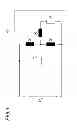
FIG. 1 shows a simplified diagram of the circuit in accordance with the invention;
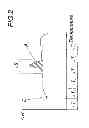
FIG. 2 shows a diagram representing the enthalpy over time during the welding process of a plastic sleeve, and
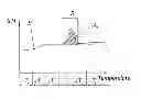
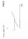
FIG. 3 shows a diagram representing the temperature progression over time in the welding region of a plastic sleeve.
DESCRIPTION OF THE PREFERRED EMBODIMENT
In order to entirely avoid the systemic weaknesses which are linked to the supply or introduction of electrically conductive cables or wires both for welding and also for temperature monitoring in the welding zone, a contactless indirect temperature measurement is provided in accordance with the invention.
For this purpose it is necessary to enable the determination of the temperature in the secondary coil, i.e. the closed heating metal, e.g. a heating metal strip, from the parameters which are transmitted via a primary coil during induction welding to the welding generator and are evaluated there. The solution to this measurement task will be described below.
In the present application, energy transmission occurs inductively from a primary air coil to the secondary side, i.e. the metal to be heated, which is a metal strip. The temperature of the metal strip must be detected without direct measurement for process and testing reasons.
Depending on the used material, the metal strip has a more or less high positive or negative temperature coefficient, i.e. it therefore consists of materials which conduct current better at lower temperatures than at high temperatures. Its electrical resistance therefore increases with rising temperature. This fact is exploited in order to detect the temperature progression during the welding process. As is shown from the drawing of the principal circuit diagram (FIG. 1), the predominantly inductive load circuit is compensated by a bypass capacitor. In FIG. 1, C1 is a bypass capacitor, X1 is a leakage inductance, X2 is an inductance for magnetization, X3 is a secondary inductance (converted to the primary side) and RL the temperature-dependent medal resistor, i.e. the strip resistance in the example. These resistors jointly form the load impedance XL applied to a supply, wherein the exciter current and the exciter voltage are applied to said load impedance.
In the illustrated model, a change in the resistance ΔRL of the strip resistance leads to a change in the total resistance ZL of the entire circuit. Irrespective of other influences such as changes in power, voltage and current, this produces a phase shift in the power supply between the supply voltage UV and the supply current IV. If the circuit is operated in the range of the resonant frequency, this leads to highly useful results. In particular, ΔRL is proportional to ΔZL, and ΔZL is equivalent to Δφ, and therefore ΔRL is equivalent to Δφ. By measuring the supply voltage UV and the supply current IV over time, especially in real time, the phase shift Δφ in the power supply and subsequently the resistance RL of the metal can be calculated by means of the mathematical model. As a result, the resistance progression can be logged during the welding process. Due to the PTC thermistor properties of the metal, i.e. the temperature dependence, this resistance progression is proportional to the temperature progression during the welding process.
RL=R0*eb(TL−T0)
R0 is the nominal resistance at room temperature T0, b is the material constant, and TL the temperature to be determined, measured and associated with the respectively calculated resistance RL.
Calibration of the circuit can be performed for example in such a way that the input frequency F of the supply voltage is changed by ΔF. This leads to a change in the load impedance XL on the basis of the model calculation, and subsequently to a defined change ΔRL in the strip resistance and a defined measured value Δφ.
A calculated value can be determined by means of the invention which is proportional to the strip heating temperature, and by means of its progression it is possible to positively illustrate the relative change of the temperature value in the welding region. All induction heating methods (e.g. also the pan base material in induction ovens) in which the secondary winding consists of material with a positive temperature coefficient could be calibrated according to this method to a relative temperature change statement and can thus be monitored.
An improved and more precise allocation to a physical measuring quantity (° C., ° K) can be achieved with the circuit described below. FIG. 2 and FIG. 3 schematically show the melting-down behavior of a semi-crystalline polymer (e.g. polyethylene). The enthalpy content H (energy quantity per gram) of the substance increases with rising temperature (T). As a result of their molecular structure, polymers do not have a defined melting point but a melting range which can be assumed as an area beneath the curve of the hatched region.
A reasonably constant temperature rise (FIG. 3) will occur with this material property in the melting-down process for thermoplastic materials with the same power supply, before and after the change in the aggregate state. In the range of crystalline melting (in the case of PE, 142° C.), an increase in the temperature in the welding spot will only occur with constant supply of energy when the material around the heating metal has converted predominantly into the plasticized state. This delay in the temperature increase at this temperature point is shown in FIG. 3.
This fact is used in accordance with the invention in such a way that in operation the resistance of the metal arranged as a PTC thermistor is always calculated and is preferably logged, wherein the resistance upon reaching the melting-down temperature of the bed remains at least virtually constant until the melting down of the bed and only rises again after the melting, and that the temperature progression calculated from the resistance progression is adjusted to the melting temperature of the bed material before the temperature progression is stored in a memory.
The measured data detected with respective software support during each welding process are “attached” to the crystalline melting point temperature after passing said temperature point, thus allowing the temperature progression to be allocated to real measured values. All values before and after can thus be allocated to a precise welding strip temperature which is precise up to a few degrees Celsius and the log files can be provided in form of respective temperature curves when calibration is performed between the temperature progression calculated from the resistance progression and the melting temperature associated with the bed material. For this purpose, the curve of the calculated temperature progression in the calculated melting range is shifted for example by the melting temperature characteristic to the material in the direction of the temperature axis.
The invention further relates to an induction welding device (not shown in closer detail), especially for induction connecting sleeves for the melting connection of wieldable thermoplastic bodies with a circuit as described above.
Claims
1. A circuit for the inductive heating of a metal that is optionally embedded in a non-magnetic bed by means of a transformer which induces eddy currents in the metal as a function of an exciter current IL and an exciter voltage UL and forms a load impedance XL together with the metal to be heated, wherein temperature monitoring is provided for the metal to be heated, wherein the load impedance XL is preferably operated in the region of the resonant frequency thereof, the exciter current IL and exciter voltage UL and their phase shift Δφ relative to each other are measured and logged when the metal is heated, and a temperature progression which is proportional to the phase shift Δφ is calculated from the exciter current IL, exciter voltage UL and phase shift Δφ.
2. The circuit according to claim 1, wherein the exciter frequency F of the exciter voltage UL applied to the load impedance XL is changed by ΔF for calibration, which produces a phase shift Δφ and a load impedance change ΔXL, which is preferably logged, wherein the change in resistance ΔR of the metal arranged as a PTC thermistor or NTC thermistor is calculated from the associated exciter current IL, the associated exciter voltage UL and the associated phase shift Δφ from a mathematical model of the load impedance XL.
3. The circuit according to claim 1, wherein in operation the resistance of the metal arranged as a PTC thermistor or NTC thermistor is always calculated and preferably logged, wherein the resistance RL remains virtually constant upon reaching a change in the aggregate state, especially upon reaching the melting-down temperature of the bed up to the melting down of the bed, and only rises again after melting down, and the temperature progression calculated from the resistance progression is calibrated to the melting temperature inherent to the bed material before the temperature progression is stored in a memory.
4. The circuit according to claim 1, wherein the metal is embedded in a plastic bed, especially one forming a connecting sleeve.
5. An induction welding device, especially for induction connecting sleeves for fusing weldable thermoplastic bodies, comprising a circuit according to claim 1.
Images & Drawings included:
Sources:
- United States Patent and Trademark Office - verify current appl. status at the USPTO↗
Recent applications in this class:
- » 20250275020 2025-08-28
INDUCTION HEATING FOR PROCESS ELECTRIFICATION - » 20250168939 2025-05-22
APPARATUS FOR HEATING SMOKABLE MATERIAL - » 20250151177 2025-05-08
INDUCTION SLAB HEATER USING PWM ZONE HEATING CONTROL WITH SELECTABLE INDUCTION FREQUENCY - » 20250071864 2025-02-27
SYSTEMS AND METHODS FOR INDUCTION COOKING WITH SUPPLEMENTAL BATTERY - » 20250056683 2025-02-13
SENSOR DEVICE AND COOKING APPLIANCE INCLUDING THE SAME - » 20250048504 2025-02-06
Induction Furnace with Electrically Separable Coil System - » 20250048503 2025-02-06
Induction Furnace with Electrically Separable Coil System - » 20250048502 2025-02-06
Induction Furnace with Electrically Separable Coil System - » 20250039998 2025-01-30
INDUCTION COIL UNIT AND METHOD FOR CONTROLLING AN INDUCTIVE HEATING PROCESS FOR AN INDUCTION COIL UNIT - » 20250024563 2025-01-16
INDUCTION HEATING OF A COMPONENT DURING DIRECT ENERGY DEPOSITION REPAIR
Recent applications for this Assignee:
- » 20150361198 2015-12-17
Stabilizer for polyolefins and process for preparing such a stabilizer - » 20150137515 2015-05-21
Plug-in coupling for a pipe, in particular for water conduits - » 20120313369 2012-12-13
Device for connecting a plastic tube to a connection nipple