Magnet wheel
US20140361644A1
2014-12-11
14/366,191
2012-12-19
✅ Patent granted
US 9,882,456 B2
2018-01-30
WO; PCT/EP2012/076069; 20121219
WO; WO2013/092653; 20130627
Bernard Rojas | Ahmed Elnakib
Cozen O'Connor
2032-12-19
Abstract:
A magnet wheel for an electric motor includes a shaft and a disk made of a plastic containing magnetic particles. The disk is arranged on a carrying hub and the carrying hub is pressed onto the shaft. The carrying hub is a slotted ring around which the disk is molded on by injection molding.
Assignee:
- CONTINENTAL AUTOMOTIVE GMBH 2,462 🇩🇪 Hannover, Germany
Applicant:
Interested in similar patents?
Get notified when new applications in this technology area are published.
Classification:
H02K11/00 IPC
Structural association of dynamo-electric machines with electric components or with devices for shielding, monitoring or protection
H02K1/27 IPC
Details of the magnetic circuit characterised by the shape, form or construction; Rotating parts of the magnetic circuit Rotor cores with permanent magnets
H02K11/21 » CPC further
Structural association of dynamo-electric machines with electric components or with devices for shielding, monitoring or protection for measuring, monitoring, testing, protecting or switching Devices for sensing speed or position, or actuated thereby
H02K29/08 » CPC further
Motors or generators having non-mechanical commutating devices, e.g. discharge tubes or semiconductor devices with position sensing devices using magnetic effect devices, e.g. Hall-plates, magneto-resistors
H02K1/30 » CPC further
Details of the magnetic circuit characterised by the shape, form or construction; Rotating parts of the magnetic circuit; Means for mounting or fastening rotating magnetic parts on to, or to, the rotor structures using intermediate parts, e.g. spiders
Description
CROSS-REFERENCE TO RELATED APPLICATIONS
This is a U.S. national stage of application No. PCT/EP2012/076069, filed on 19 Dec. 2012, which claims priority to the German Application No. 10 2011 089 243.5, filed 20 Dec. 2011, the content of both incorporated herein by reference.
BACKGROUND OF THE INVENTION
1. Field of the Invention
The present invention relates to a magnet wheel for an electric motor, having a shaft and a disk made of a plastic containing magnetic particles. The disk is arranged on a support hub, and the support hub is pressed with the shaft.
2. Related Art
Such magnet wheels are used in brushless DC motors as part of position sensors and are therefore known. The disk of the magnet wheel is produced by injection molding a plastic containing iron particles onto the support hub. The support hub is a closed ring made of a suitable material, such as steel or brass. Then, the support hub, with the disk injection-molded on, is pressed onto the shaft. The disadvantage with this configuration is that, owing to manufacturing tolerances of the shaft, considerable stresses sometimes occur in the support huh when the support hub is pressed on, and these stresses reduce the life of the magnet wheel. In particularly severe cases, there is the risk of the magnet wheel being impaired, which may result in malfunctions in the position sensor.
SUMMARY OF THE INVENTION
An object of the invention is therefore to provide a magnet wheel in which loads occurring due to manufacturing do not result in individual parts being impaired.
This object is achieved in that the support hub is in the form of a slotted ring, around which the disk is formed integrally by means of injection molding.
The slotted design of the support hub enables a substantially improved response to tolerances of the shaft. The support hub thus surrounds the shaft as a type of spring and can thus expand in the case of larger shaft diameters. In this way, stresses in the support huh are markedly reduced, which increases the life of the magnet wheel. Owing to the increased toughness of the plastic, the expansion of the support hub does not substantially contribute to an increase in the stresses in the disk. A further advantage is that, owing to the slotted support hub, relatively large manufacturing tolerances in respect of the shaft diameter and the hub bore are also permissible, which simplifies manufacture.
Manufacture is very inexpensive if the ring for the support hub is rolled from tape material.
In another configuration, the ring for the support hub can be a turned or stamped part into which a slot is introduced, as has previously been the case. This is advantageous in particular when the ring is still being machined prior to being encapsulated by injection molding.
As a result of the expansion of the support hub, a relative movement of the disk and the support hub can take place. In this case, it has proven to be advantageous to connect the support hub and the disk to one another for safe torque transmission by virtue of the support hub having a notch radially on the outside.
A secure connection between the support hub and the disk without preventing the expansion of the support hub in the process is achieved with a notch when the notch is arranged in a region whose ends are arranged at least 90° away from the slot. Accordingly, no notch is arranged in each case at least 90° to the left and to the right of the slot. In this region, a relative movement between the disk and the support hub can occur during expansion. Stresses are thus minimized.
An intimate connection between the support hub and the disk is achieved with a. notch. in the form of at least one impressed portion, preferably in the form of a knurl.
In another configuration, the notch can be produced in a particularly simple manner when it is a single cutout in the support hub, which is arranged opposite the slot. A single cutout is often sufficient owing to the low torque to be transmitted. In addition, advantageously such wide regions of the support hub are provided that a relative movement between the plastic and the support hub is permitted.
For relatively large torque transmissions, two to four cutouts can be arranged in the support hub, which are arranged symmetrically with respect to the slot.
BRIEF DESCRIPTION OF THE DRAWINGS
The invention will be explained in more detail with reference to an exemplary embodiment. In the drawings:
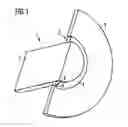
FIG. 1 shows a magnet wheel in a half-section; and
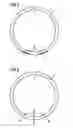
FIGS. 2 and 3 show further embodiments of the support hub.
DETAILED DESCRIPTION OF THE PRESENTLY PREFERRED EMBODIMENTS
As seen in FIG. 1, a magnet wheel 1 comprises a shaft 2, which can be the shaft of an electronically commutated electric motor, and a disk 3 made of ferrite-bonded plastic. The plastic is integrally formed on a support hub 4 by injection molding. The support hub has a slot 5, which is arranged in the section plane for improved clarity. As illustrated in FIGS. 1 and 3, the support hub 4 has a notch 6 that may be in the form of a cutout 8 radially on the outside opposite the slot 5 and thus at a distance of 180°. During injection-molding of the ferrite-bonded plastic, the ferrite-bonded plastic fills the notch 6 and thus produces an intimate compound structure with the support hub 4. When the support hub 4 is pressed with the disk 3 onto the shaft 2, the support hub 4 can expand, wherein this may result in relative movements between the support hub 4 and the disk 3 in the regions to the right and left of the slot 5.
The support hub 4 is illustrated without the disk and the shaft in FIGS. 2 and 3. FIG. 2 shows the support hub 4 with a notch 6 in the form of two knurls 7. The knurls 7 are arranged in a region symmetrically opposite the slot 5 and extends over 60°. The knurls 7 each extend over a region of 20° and have a distance from one another of 20° C. The knurls 7 thus have a distance from the slot 5 of 150°. The support hub 4 in FIG. 3 has a notch 6 in the form of three cutouts 8 arranged symmetrically with respect to the slot 5, which cutouts have a distance from one another of 30°.
Thus, while there have been shown and described and pointed out fundamental novel features of the invention as applied to a preferred embodiment thereof, it will be understood that various omissions and substitutions and changes in the form and details of the devices illustrated, and in their operation, may be made by those skilled in the art without departing from the spirit of the invention. For example, it is expressly intended that all combinations of those elements and/or method steps which perform substantially the same function in substantially the same way to achieve the same results are within the scope of the invention. Moreover, it should be recognized that structures and/or elements and/or method steps shown and/or described in connection with any disclosed form or embodiment of the invention may be incorporated in any other disclosed or described or suggested form or embodiment as a general matter of design choice. It is the intention, therefore, to be limited only as indicated by the scope of the claims appended hereto.
Claims
1-8. (canceled)
9. A magnet wheel for an electric motor, comprising:
a shaft (2);
a disk (3) made of a plastic containing magnetic particles; and
a support hub (4) on which the disk (3) is arranged, the support hub (4) being pressed with the shaft (2),
wherein the support hub (4) is a slotted ring around which the disk (3) is formed integrally by injection molding.
10. The magnet wheel as claimed in claim 9, wherein the support hub (4) is rolled from tape material.
11. The magnet wheel as claimed in claim 9, wherein the support hub (4) is a turned or stamped part into which a slot (5) is introduced.
12. The magnet wheel as claimed in claim 11, wherein the support hub (4) has a notch (6) radially on an outside portion of the support hub (4).
13. The magnet wheel as claimed in claim 12, wherein the notch (6) is arranged in a region, and the ends of the region are arranged at least 90° away from the slot (5).
14. The magnet wheel as claimed in claim 13, wherein the notch (6) is in the form of at least one impressed portion.
15. The magnet wheel as claimed in claim 12, wherein the notch (6) is a single cutout (8) in the support hub (4), which cutout is arranged opposite the slot (5).
16. The magnet wheel as claimed in claim 13, wherein the notch (6) comprises two to four cutouts (8) in the support hub (4), the cutouts being arranged symmetrically with respect to the slot (5).
17. The magnet wheel as claimed in claim 14, wherein the at least one impressed portion is in the form of a knurl (7).
Images & Drawings included:
Sources:
- United States Patent and Trademark Office - verify current appl. status at the USPTO↗
Similar patent applications:
- » 20170019002
Method for forging magnet wheel for motor vehicle alternator using cold forging die, and magnet wheel obtained by this method - » 20140232379
Magnetic field sensor system with a magnetic wheel rotatable around a wheel axis and with magnetic sensor elements being arranged within a plane perpendicular to the wheel axis - » 20170093234
Forged magnet wheel for motor vehicle alternator provided with permanent interpolar magnets - » 20060162610
Magnetic wheel for vehicles - » 20050104469
Brushless permanent magnet wheel motor with variable axial rotor/stator alignment - » 20060049712
Brushless permanent magnet wheel motor with variable axial rotor/stator alignment - » 20070281837
Controller for magnetic wheels - » 20060027952
Steerable magnetic wheel carriage - » 20070170791
Magnet wheel alternator/ generator electricity producing wheel - » 20060022540
Magnet wheel of an internal combustion engine
Recent applications in this class:
- » 20170155306 2017-06-01
Brushless D.C. motor with improved rotor magnet position sensing - » 20160190898 2016-06-30
Motor unit having a detector interposed between a motor and an arithmetic board - » 20160072366 2016-03-10
Drive apparatus and robot device - » 20160056691 2016-02-25
SELF-CENTERING FOR ENCODER DEVICE - » 20150381016 2015-12-31
Motor actuator - » 20150280528 2015-10-01
Speed detection circuits for permanent magnet alternators - » 20150097461 2015-04-09
Rotating Electrical Machine - » 20150054389 2015-02-26
Homopolar permanent-magnet-biased action magnetic bearing with an integrated rotational speed sensor - » 20150048724 2015-02-19
Control apparatus for controlling rotation of joints of robot - » 20150022064 2015-01-22
Driving apparatus
Recent applications for this Assignee:
- » 20250006057 2025-01-02
VEHICLE-EXIT ASSIST APPARATUS - » 20240312120 2024-09-19
METHOD AND DEVICE FOR PROVIDING A VISUALIZATION OF A VEHICLE, AND VEHICLE - » 20240295913 2024-09-05
ELECTRONIC DEVICE AND METHOD OF RESPONDING TO A TRIGGER TO WAKE UP - » 20240126118 2024-04-18
Display system and method for operating a display system - » 20240103589 2024-03-28
Frame for an electro-optical display and electro-optical display having a frame - » 20240103348 2024-03-28
Device for securing an optical device - » 20240103153 2024-03-28
Distance measuring system - » 20240100956 2024-03-28
Control unit circuit for a motor vehicle, motor vehicle and operating method for the control unit circuit - » 20240053161 2024-02-15
Method for predicting a velocity profile of a vehicle - » 20230356682 2023-11-09
Method for adapting a triggering algorithm of a personal restraint device and control device for adapting a triggering algorithm of a personal restaint device