Thermally conductive body and electronic device using same
US20140362532A1
2014-12-11
14/372,645
2013-03-11
✅ Patent granted
US 9,491,890 B2
2016-11-08
WO; PCT/JP2013/001552; 20130311
WO; WO2013/140741; 20130926
Courtney Smith | Michael Matey
McDermott Will & Emery LLP
2033-03-20
Abstract:
A thermally conductive body includes an insulating sheet, a first graphite sheet provided on a first surface of the insulating sheet, and a second graphite sheet provided on a second surface that is a reverse side of the first surface of the insulating sheet. Compressibility of the insulating sheet is lower than compressibility of the first graphite sheet and compressibility of the second graphite sheet.
Assignee:
- Panasonic Intellectual Property Management Co., Ltd. 13,392 🇯🇵 Osaka, Japan
Applicant:
Interested in similar patents?
Get notified when new applications in this technology area are published.
Classification:
H05K7/2039 » CPC main
Constructional details common to different types of electric apparatus; Modifications to facilitate cooling, ventilating, or heating characterised by the heat transfer by conduction from the heat generating element to a dissipating body
H05K7/2039 » CPC main
Constructional details common to different types of electric apparatus; Modifications to facilitate cooling, ventilating, or heating characterised by the heat transfer by conduction from the heat generating element to a dissipating body
H05K7/20 IPC
Constructional details common to different types of electric apparatus Modifications to facilitate cooling, ventilating, or heating
H05K7/20 IPC
Constructional details common to different types of electric apparatus Modifications to facilitate cooling, ventilating, or heating
F28F3/00 » CPC further
Plate-like or laminated elements; Assemblies of plate-like or laminated elements
H01L23/3735 » CPC further
Details of semiconductor or other solid state devices; Arrangements for cooling, heating, ventilating or temperature compensation ; Temperature sensing arrangements; Selection of materials, or shaping, to facilitate cooling or heating, e.g. heatsinks; Cooling facilitated by selection of materials for the device or materials for thermal expansion adaptation, e.g. carbon Laminates or multilayers, e.g. direct bond copper ceramic substrates
H01L23/373 » CPC further
Details of semiconductor or other solid state devices; Arrangements for cooling, heating, ventilating or temperature compensation ; Temperature sensing arrangements; Selection of materials, or shaping, to facilitate cooling or heating, e.g. heatsinks Cooling facilitated by selection of materials for the device or materials for thermal expansion adaptation, e.g. carbon
H01L2924/0002 » CPC further
Indexing scheme for arrangements or methods for connecting or disconnecting semiconductor or solid-state bodies as covered by; Technical content checked by a classifier Not covered by any one of groups , and
H01L23/36 » CPC further
Details of semiconductor or other solid state devices; Arrangements for cooling, heating, ventilating or temperature compensation ; Temperature sensing arrangements Selection of materials, or shaping, to facilitate cooling or heating, e.g. heatsinks
Description
TECHNICAL FIELD
The present invention relates to a thermally conductive body used in various electronic devices, and an electronic device using the same.
BACKGROUND ART
Recently, with increase in functions, processing performance, and the like, of electronic devices, an amount of heat generated from electronic components such as a semiconductor element has been increased. In order to improve an operation property, reliability, and the like, of electronic components, a method of transferring heat by sandwiching a thermally conductive body between an electronic component as a heat generating body and a heat sink (a heat-dissipating plate) is used. FIG. 4 is a sectional view of a conventional thermally conductive body. Thermally conductive body 10 is formed by covering both sides of graphite sheet 1 having excellent thermal conductivity with insulating sheet 2. Insulating sheet 2 is used to keep an insulating property between a heat generating body (not shown) and a heat sink (not shown).
Note here that prior art literatures on the invention in accordance with the present application include, for example, Patent Literature 1.
CITATION LIST
Patent Literature
PTL 1: Japanese Patent Application Unexamined Publication No. 2011-105531
SUMMARY OF THE INVENTION
A thermally conductive body of the present invention includes an insulating sheet, a first graphite sheet provided on a first surface of the insulating sheet, and a second graphite sheet provided on a second surface that is a reverse side of the first surface of the insulating sheet. Compressibility of the insulating sheet is lower than compressibility of the first graphite sheet and compressibility of the second graphite sheet.
BRIEF DESCRIPTION OF THE DRAWINGS
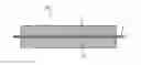
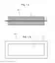
FIG. 1A is a sectional view of a thermally conductive body in accordance with an exemplary embodiment of the present invention.
FIG. 1B is a top view of the thermally conductive body in accordance with the exemplary embodiment of the present invention.
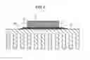
FIG. 2 is a sectional view of an electronic device using the thermally conductive body in accordance with the exemplary embodiment of the present invention.
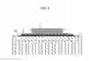
FIG. 3 is a sectional view of another electronic device using the thermally conductive body in accordance with the exemplary embodiment of the present invention.
FIG. 4 is a sectional view of a conventional thermally conductive body.
DESCRIPTION OF EMBODIMENTS
Hereinafter, a thermally conductive body in accordance with an exemplary embodiment of the present invention is described with reference to drawings.
FIG. 1A is a sectional view of thermally conductive body 100 in accordance with this exemplary embodiment. FIG. 1B is a top view of thermally conductive body 100 in accordance with this exemplary embodiment. Thermally conductive body 100 includes insulating sheet 13, first graphite sheet 11 provided on a first surface of insulating sheet 13, and second graphite sheet 12 provided on a second surface that is a reverse side of the first surface of insulating sheet 13. Insulating sheet 13 is formed by coating an adhesive agent including acrylic resin on both surfaces of a polyethylene terephthalate sheet. A thickness of first graphite sheet 11 is about 70 μm, a thickness of second graphite sheet 12 is about 70 μm, a thickness of polyethylene terephthalate is about 2 μm, and a thickness of the adhesive agent is about 4 μm.
A pyrolytic graphite sheet, which is graphitized by thermally decomposing and carbonizing a resin film of, for example, polyimide, followed by heat treatment at a high temperature, is used as first and second graphite sheets 11 and 12.
First and second graphite sheets 11 and 12 have an air space inside thereof and have compressibility of about 15%. Herein, the compressibility is defined as (t0−t1)/t0 in which t1 is a thickness when a pressure of 2 kg-wt/cm2 is applied to a sheet having thickness t0. On the other hand, since polyethylene terephthalate is used for insulating sheet 13, the compressibility of insulating sheet 13 is less than 1%. That is to say, the compressibility of insulating sheet 13 is much lower than that of first and second graphite sheets 11 and 12.
Next, a use state of the thermally conductive body is described. FIG. 2 is a sectional view of an electronic device using thermally conductive body 100 in accordance with this exemplary embodiment. Thermally conductive body 100 is sandwiched between heat generating body 14 such as a semiconductor element and heat sink 15 made of aluminum. Heat generating body 14 is brought into direct contact with second graphite sheet 12, and heat sink 15 is brought into direct contact with first graphite sheet 11.
Although heat generating body 14 is locally heated to high temperatures, since heat generating body 14 is brought into direct contact with second graphite sheet 12, heat spreads throughout second graphite sheet 12 rapidly. The heat is transferred to first graphite sheet 11 via insulating sheet 13, and dissipated from heat sink 15.
In a conventional thermally conductive body 10 shown in FIG. 4, insulating sheet 2 is attached to the both surfaces of graphite sheet 1. That is to say, insulating sheet 2 is brought into contact with a heat generating body and a heat sink. Therefore, thermal resistance (contact thermal resistance) is increased in a portion in which insulating sheet 2 is brought into contact with the heat generating body or the heat sink, thus making it difficult to transfer heat as a whole (deteriorating a heat transferring efficiency).
However, in thermally conductive body 100, insulating sheet 13 is sandwiched between first graphite sheet 11 and second graphite sheet 12. First graphite sheet 11 is brought into contact with heat sink 15, and second graphite sheet 12 is brought into contact with heat generating body 14.
First graphite sheet 11 is easily deformed due to its high compressibility and adheres to heat sink 15. Therefore, the contact thermal resistance between first graphite sheet 11 and heat sink 15 can be reduced. Furthermore, second graphite sheet 12 is also easily deformed due to its high compressibility and adheres to heat generating body 14. Therefore, the contact thermal resistance between second graphite sheet 12 and heat generating body 14 can be reduced.
Furthermore, insulating sheet 13 having low compressibility and being hard is sandwiched between first graphite sheet 11 and second graphite sheet 12 having high compressibility. Therefore, even when a pressure is applied, the shape of the whole of thermally conductive body 100 is maintained and the insulation property in a thickness direction can be secured.
That is to say, one surface of the graphite sheet (first graphite sheet 11 or second graphite sheet 12) is brought into contact with heat generating body 14 or heat sink 15, and the other surface is supported by insulating sheet 13 having lower compressibility than that of the graphite sheet. With this configuration, since the graphite sheet and heat generating body 14 or heat sink 15 adhere to each other when a pressure is applied, the contact thermal resistance can be reduced.
In order to allow first graphite sheet 11 to adhere to heat sink 15 and allow second graphite sheet 12 to adhere to heat generating body 14, respectively, the compressibility of first graphite sheet 11 and the compressibility of second graphite sheet 12 are desirably not less than 10%. Furthermore, from the viewpoint of handling of thermally conductive body 100, the compressibility of first graphite sheet 11 and the compressibility of second graphite sheet 12 are desirably not more than 50%. In addition, it is desirable that the compressibility of insulating sheet 13 is not more than one-tenth of the compressibility of first graphite sheet 11 and the compressibility of second graphite sheet 12. Furthermore, when the compressibility of first graphite sheet 11 and second graphite sheet 12 are made to be thicker than insulating sheet 13, adhesion is further improved.
Herein, it is desirable that an area in a top view of insulating sheet 13 is larger than that of first graphite sheet 11 and second graphite sheet 12. That is to say, as shown in FIG. 1B, it is desirable that in a cross section in a direction in which first graphite sheet 11, insulating sheet 13 and second graphite sheet 12 are laminated, insulating sheet 13 extends off at the whole periphery.
Thus, the insulation property (that is to say, the insulation property in the thickness direction) of heat generating body 14 and heat sink 15 can be secured.
In addition, it is desirable that the peripheral part of insulating sheet 13 is attached to heat sink 15. Thus, the contact thermal resistance between first graphite sheet 11 and heat sink 15 can be further reduced.
FIG. 3 is a sectional view of another electronic device using thermally conductive body 100 in accordance with this exemplary embodiment. In this configuration, protective film 16 is provided on a surface, in which second graphite sheet 12 is brought into contact with heat generating body 14, in a region with which second graphite sheet 12 is not brought into contact. That is to say, the protective film is formed on a part of the second graphite sheet. When a part of second graphite sheet 12 is covered with protective film 16, a region in which second graphite sheet 12 is exposed can be reduced, thus improving the reliability.
Furthermore, since protective film 16 is not provided in a region in which second graphite sheet 12 is brought into contact with heat generating body 14, heat generating body 14 is brought into direct contact with second graphite sheet 12, and thus the contact thermal resistance therebetween can be reduced.
Note here that this exemplary embodiment describes a case in which a single layer of an insulating sheet is provided. However, a plurality of graphite sheets and insulating sheets may be laminated alternately. In this case, a configuration may be employed, in which a part that is brought into contact with a heat generating body or a heat sink is a graphite sheet, and a part opposite to the contact graphite sheet is made of an insulating sheet having lower compressibility than that of the graphite sheet.
As mentioned above, when thermally conductive body 100 in accordance with this exemplary embodiment is used, the contact thermal resistance can be reduced while the insulation property between heat generating body 14 and heat sink 15 can be secured.
INDUSTRIAL APPLICABILITY
A thermally conductive body of the present exemplary embodiment is excellent in the thermal conductivity and insulation property in a thickness direction, and is industrially applicable.
REFERENCE MARKS IN THE DRAWINGS
11 first graphite sheet
12 second graphite sheet
13 insulating sheet
14 heat generating body
15 heat sink
16 protective film
100 thermally conductive body
Claims
1. A thermally conductive body comprising:
an insulating sheet;
a first graphite sheet provided on a first surface of the insulating sheet; and
a second graphite sheet provided on a second surface that is a reverse side of the first surface of the insulating sheet,
wherein compressibility of the insulating sheet is lower than compressibility of the first graphite sheet and compressibility of the second graphite sheet.
2. The thermally conductive body of claim 1, wherein the compressibility of the first graphite sheet and the compressibility of the second graphite sheet are not less than 10% and not more than 50%.
3. The thermally conductive body of claim 1, wherein the compressibility of the insulating sheet is not more than one-tenth of the compressibility of the first graphite sheet and the compressibility of the second graphite sheet.
4. The thermally conductive body of claim 1, wherein, in a top view, an area of the insulating sheet is larger than an area of the first graphite sheet and an area of the second graphite sheet.
5. The thermally conductive body of claim 1, wherein the first graphite sheet and the second graphite sheet are thicker than the insulating sheet.
6. The thermally conductive body of claim 1, further comprising a protective film in a part of the second graphite sheet.
7. An electronic device comprising:
a thermally conductive body of claim 1;
a heat sink brought into direct contact with the first graphite sheet of the thermally conductive body; and
a heat generating body brought into direct contact with the second graphite sheet of the thermally conductive body.
8. The electronic device of claim 7, wherein a protective film is formed on the second graphite sheet in a region with which the heat generating body is not brought into contact.
Images & Drawings included:

Sources:
- United States Patent and Trademark Office - verify current appl. status at the USPTO↗
Recent applications in this class:
- » 20250294709 2025-09-18
MECHANICAL PUMP-FREE FLOW BOILING HEAT SINK - » 20250287542 2025-09-11
CIRCUIT ASSEMBLY - » 20250287541 2025-09-11
VAPOR CHAMBER - » 20250287540 2025-09-11
ELECTRONIC APPARATUS - » 20250287539 2025-09-11
HEAT SINK AND DISPLAY DEVICE INCLUDING THE SAME - » 20250280515 2025-09-04
COOLING INTERFACE FOR A PLUGGABLE MODULE - » 20250275098 2025-08-28
IMAGING APPARATUS - » 20250275097 2025-08-28
COOLING SYSTEMS INCLUDING STACKS WITH FINS - » 20250261338 2025-08-14
HEAT DISSIPATION MEMBER AND ELECTRONIC DEVICE - » 20250261337 2025-08-14
PLANAR ASSEMBLY HANDLE FOR HEAT SINK OPTIMIZATION
Recent applications for this Assignee:
- » 20250291148 2025-09-18
LENS BARREL AND CAMERA EQUIPPED WITH SAME - » 20250290210 2025-09-18
METHOD FOR CLEAVING DISULFIDE BOND IN PROTEIN AND DEVICE FOR CLEAVING DISULFIDE BOND IN PROTEIN - » 20250289467 2025-09-18
INFORMATION PROCESSING METHOD, COMPUTER PROGRAM PRODUCT, AND INFORMATION PROCESSING APPARATUS - » 20250286901 2025-09-11
DETECTION SYSTEM, DETECTION METHOD, AND RECORDING MEDIUM - » 20250282444 2025-09-11
DRIVE UNIT AND ELECTRIC VEHICLE - » 20250280188 2025-09-04
FILTER MODULE FOR IMAGING APPARATUS - » 20250277834 2025-09-04
INSULATION RESISTANCE DETECTION DEVICE AND INSULATION RESISTANCE DETECTION METHOD - » 20250274653 2025-08-28
ELECTRONIC DEVICE AND SHOOTING MANAGEMENT METHOD - » 20250273929 2025-08-28
LIGHT-EMITTING SYSTEM - » 20250273056 2025-08-28
PORTABLE PAYMENT TERMINAL