Device for joining hybrid electrical transmission cables
US20150075864A1
2015-03-19
14/467,241
2014-08-25
✅ Patent granted
US 9,379,531 B2
2016-06-28
-
-
Timothy Thompson | Rhadames J Alonzo Miller
Sofer & Haroun, LLP
2034-08-25
Abstract:
A device is provided for connecting two hybrid electrical transmission cables each having stranded first conductive wires made of a first metal in the central zone of the cable and second conductive wires that are made of a second metal of higher hardness than that of the first metal and wound on and outside this central zone, the second conductive wires of the cables being connected by an external conductive sleeve. The central first wires of the cables are connected by a weld made of the first metal and connecting their end, this weld and this end being covered by a tube of metal of hardness equal to or higher than that of the second wires, at least partially in line with the sleeve, the end of the second wires being re-formed on the first wires and on the tube under the external conductive sleeve.
Assignee:
- NEXANS 286 🇫🇷 Paris, France
Applicant:
Interested in similar patents?
Get notified when new applications in this technology area are published.
Classification:
H02G1/14 » CPC further
Methods or apparatus specially adapted for installing, maintaining, repairing or dismantling electric cables or lines for joining or terminating cables
H02G15/076 » CPC main
Cable fittings; Cable terminations; Cable terminating boxes, frames, or other structures for multi-conductor cables
H01R4/46 » CPC further
Electrically-conductive connections between two or more conductive members in direct contact, i.e. touching one another; Means for effecting or maintaining such contact; Electrically-conductive connections having two or more spaced connecting locations for conductors and using contact members penetrating insulation; Clamped connections, spring connections utilising a clamping member acted on by screw or nut Clamping area between two screws placed side by side
Y10T29/49195 » CPC further
Metal working; Method of mechanical manufacture; Electrical device making; Conductor or circuit manufacturing; Assembling elongated conductors, e.g., splicing, etc. with end-to-end orienting
H01R4/021 » CPC further
Electrically-conductive connections between two or more conductive members in direct contact, i.e. touching one another; Means for effecting or maintaining such contact; Electrically-conductive connections having two or more spaced connecting locations for conductors and using contact members penetrating insulation; Soldered or welded connections between two or more cables or wires
H01R4/20 » CPC further
Electrically-conductive connections between two or more conductive members in direct contact, i.e. touching one another; Means for effecting or maintaining such contact; Electrically-conductive connections having two or more spaced connecting locations for conductors and using contact members penetrating insulation effected solely by twisting, wrapping, bending, crimping, or other permanent deformation by crimping using a crimping sleeve
Y10T29/49199 » CPC further
Metal working; Method of mechanical manufacture; Electrical device making; Conductor or circuit manufacturing; Assembling elongated conductors, e.g., splicing, etc. with end-to-end orienting including deforming of joining bridge
H02G15/00 IPC
Cable fittings
H02G15/02 IPC
Cable fittings Cable terminations
H01R43/04 IPC
Apparatus or processes specially adapted for manufacturing, assembling, maintaining, or repairing of line connectors or current collectors or for joining electric conductors for forming connections by deformation, e.g. crimping tool
H02G15/18 » CPC further
Cable fittings; Cable junctions protected by sleeves, e.g. for communication cable
H01R4/02 IPC
Electrically-conductive connections between two or more conductive members in direct contact, i.e. touching one another; Means for effecting or maintaining such contact; Electrically-conductive connections having two or more spaced connecting locations for conductors and using contact members penetrating insulation Soldered or welded connections
H01R43/00 IPC
Apparatus or processes specially adapted for manufacturing, assembling, maintaining, or repairing of line connectors or current collectors or for joining electric conductors
Description
RELATED APPLICATION
This application claims the benefit of priority from French Patent Application No. FR 13 58488, filed on Sep. 5, 2013, the entirety of which is incorporated by reference.
BACKGROUND
1. Field of the Invention
The invention relates to a device for joining hybrid electrical transmission cables.
As described in patent document CN 2006/20073616, it is known to produce hybrid electrical transmission cables comprising stranded conductive wires made of aluminum in the central zone of the cable and coiled conductive wires made of copper on and outside this central zone.
The invention provides a device for joining such hybrid electrical transmission cables in particular intended for high voltages.
2. Description of the Related Art
Patent document WO 2011/103036 relates to a device for connecting cables comprising a central supporting core made up of composite wires comprising fibers embedded in a matrix that may be made of aluminum, on which core conductive metal wires, which may be made of copper, are wound.
In this device, the central core of the abutted cables is stripped of conductive wires that are removed over a corresponding length and the two abutted cores are connected via a tube equipped with internal sleeves, into which tube their end is inserted and crimped.
As regards connection of the external conductive wires, it is achieved by means of an external metal connector tube that is crimped at its ends onto the conductive wires on each side of the connecting device.
Although such a connecting device may be suitable for cables in which the central core acts as a mechanical support for the external conductive wires, it is unable, in the case of hybrid cables such as described above in which the central aluminum wires have an electrical transmission function, to ensure the electrical withstand of the connection, above all at high voltages.
Objects and Summary
To solve this problem, the invention provides a device for connecting hybrid electrical transmission cables ensuring an optimal electrical withstand, in particular at high voltages.
To do this, the invention provides a connecting device comprising two hybrid electrical transmission cables each comprising stranded first conductive wires made of a first metal in the central zone of the cable and second conductive wires that are made of a second metal of higher hardness than that of said first metal and wound on and outside this central zone, said second conductive wires of said cables being connected by an external conductive sleeve, characterized in that said central first wires of the cables are connected by a weld made of said first metal and connecting their end, this weld and this end being covered by a tube of metal of hardness equal to or higher than that of said second wires, at least partially in line with said sleeve, the end of said second wires being re-formed on said first wires and on said tube under said external conductive sleeve.
Although, according to the preferred embodiment, the first metal is aluminum and the second metal is copper, the connecting device according to the invention is in general particularly suitable for cables each comprising stranded first conductive wires made of a first metal in the central zone of the cable and second conductive wires that are made of a second metal of higher hardness than that of said first metal and wound on and outside this central zone.
Welding the central first wires of the cables ensures a good transmission and that these wires have a good electrical withstand.
The metal tube of higher hardness mechanically protects these first wires made of a metal of hardness lower than that of the second wires and allows the external conductive sleeve that is compressibly crimped on the re-formed second wires or screwed onto the latter to be fitted.
According to a preferred embodiment, said first metal is aluminum, said second metal is copper and said tube is made of steel or hard copper.
Preferably, said second wires at least partially cover said tube.
Said external conductive sleeve may be crimped or screwed.
The invention also relates to a method for producing such a connecting device, characterized in that the end of said first wires is freed by folding back said second wires before said weld is formed and said tube is fitted and in that the end of said second wires is re-formed on said first wires and on said tube before said external conductive sleeve is fitted.
According to a preferred embodiment, said weld is a braze.
This weld may also for example be produced by TIG (tungsten inert gas) welding.
The external conductive sleeve may be crimped or screwed.
BRIEF DESCRIPTION OF THE DRAWINGS
The invention is described in more detail below by way of the figures that show only one preferred embodiment of the invention.
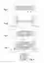
FIGS. 1 to 4 are longitudinal cross-sectional views illustrating the production of a connecting device according to a first embodiment of the invention.
FIG. 5 is a cross-sectional view along V-V in FIG. 4.
FIGS. 6 and 7 are complete and partial longitudinal, cross-sectional views showing a connecting device according to a second embodiment of the invention.
DETAILED DESCRIPTION
As shown in FIG. 1, two hybrid electrical transmission cables 1A, 1B each comprise stranded first conductive wires 2A, 2B made of a first metal in the central zone of she cable and second conductive wires 3A, 3B that are made of a second metal of higher hardness than that of the first metal and wound on and outside this central zone. They are abutted against each other in order to connect them electrically.
In the preferred application of the invention, said first metal is aluminum and said second metal is copper.
As shown in FIG. 2, the end of the first wires 2A, 2B is freed by unwinding and folding back the second wires 3A, 3B.
The central first wires 2A, 2B of the cables are then connected by an aluminum braze 4 that connects their end. This braze 4 fills the space that exists between the abutted ends of the first wires 2A, 2B while connecting the wires in a particularly effective way as the wires themselves melt over a length of about 10 mm on each side of this filled space.
As may be seen in FIG. 3, this braze 4 and these ends are then covered with a tube 5 of metal of hardness equal to or higher than that of the second wires, preferably made of steel or of hard copper, at least in line with a sleeve 6 that is compressibly crimped onto the second conductive wires once the end of the second wires 3A, 3B has been re-formed on the first wires 2A, 2B and on the tube 5, the second wires therefore at least partially covering the tube 5.
Preferably, as illustrated in FIGS. 4 and 5, the connecting device is produced with the end of the two cables 1A, 1B stripped of their insulating cladding 4A, 4B over a relatively limited length. In order to re-form this insulation in line with the connecting device, grooves 5A, 5B are machined at the end of these claddings 4A, 4B and an insulating jacket 7 is fitted by its ends into these grooves 5A, 5B and covers the connecting device.
The tube 5 then consists of two half-cylinders, namely a cylinder cut along two of its generatrices, which half-cylinders are applied around the braze 4 and a portion of the ends of the second wires 3A, 3B.
Likewise, the sleeve 6 also consists of two longitudinal half-cylinders that are crimped onto these second wires 3A, 3B.
FIGS. 6 and 7 show a connecting device also produced with the same steps as previously, but here comprising an external conductive sleeve 6′ employing screws 6′A.
In any case, the two half-cylindrical portions of the external conductive sleeve are screwed together, for example at four points level with the ends, in order to keep them in place before the sleeve assembly is crimped or screwed.
Claims
1. Connecting device comprising:
two hybrid electrical transmission cables each having stranded first conductive wires made of a first metal in the central zone of the cable and second conductive wires that are made of a second metal of higher hardness than that of said first metal and wound on and outside this central zone,
said second conductive wires of said cables being connected by an external conductive sleeve,
wherein said central first wires of the cables are connected by a weld made of said first metal and connecting their end, this weld and this end being covered by a tube of metal of hardness equal to or higher than that of said second wires, at least partially in line with said sleeve, the end of said second wires being re-formed on said first wires and on said tube under said external conductive sleeve.
2. Device according co claim 1, wherein said first metal is aluminum, said second metal is copper and said tube is made of steel or hard copper.
3. Device according to claim 1, wherein said second wires at least partially cover said tube.
4. Connecting device according to claim 1, wherein said external conductive sleeve is crimped or screwed.
5. Method for producing a connecting device according to claim 1, wherein the end of said first wires is freed by folding back said second wires before said weld is formed and said tube is fitted and in that the end of said second wires is reformed on said first wires and on said tube before said external conductive sleeve is fitted.
6. Method according to claim 5, wherein said weld is a braze.
7. Method according to claim 5, wherein said external conductive sleeve is crimped or screwed.
Images & Drawings included:


Sources:
- United States Patent and Trademark Office - verify current appl. status at the USPTO↗
Recent applications in this class:
- » 20250174975 2025-05-29
MODULAR CONNECTION SYSTEM AND METHOD - » 20210281060 2021-09-09
Cable terminating assembly with electrically insulating cutting blades - » 20200021097 2020-01-16
SHAPE MEMORY ANCHOR FOR UMBILICAL TERMINATION - » 20160315459 2016-10-27
Electrical connection box and wire harness - » 20160315458 2016-10-27
Electrical connection box and wire harness - » 20160111864 2016-04-21
Wiring carrier - » 20150155697 2015-06-04
Environmentally sealed cable breakout assemblies - » 20110108306 2011-05-12
Right angle twisted pair connector - » 20090103877 2009-04-23
Cable sleeve for the structured storage and handling of optical waveguides guided in optical waveguide cables - » 20060202434 2006-09-14
Cable sealing and/or feedthrough device
Recent applications for this Assignee:
- » 20170302062 2017-10-19
Threaded hole retainer - » 20170201084 2017-07-13
Sealing the connection point between two conductors - » 20170169915 2017-06-15
Electrical conductor for aeronautical applications - » 20170141506 2017-05-18
Device and method protecting a connector from debris while validating connector position assurance engagement - » 20170023746 2017-01-26
Reversible polarity MPO fiber optic connector with a removable key - » 20160380379 2016-12-29
Coupling part for an electrical conductor - » 20160261103 2016-09-08
Termination unit for a superconducting cable - » 20160141074 2016-05-19
Semi-conductive rubber shielded shuttle car cable - » 20160134095 2016-05-12
Termination of strength members of deep water cables - » 20160125974 2016-05-05
Medium- or high-voltage electric device