Hub-bearing assembly
US20150156954A1
2015-06-11
14/561,917
2014-12-05
✅ Patent granted
US 9,226,441 B2
2016-01-05
-
-
Phillip A Johnson
Bryan Peckjian | SKF USA Inc. Patent Dept.
2034-12-05
Abstract:
A hub-bearing assembly for agricultural use having a rolling bearing, a housing, a closing cap and an axial retention feature. The roller bearing includes an outer ring, at least one inner ring, at least a row of rolling bodies and a sealing device. The housing includes an almost annular cylindrical shape, the housing at one end forming a radial flange, containing the rolling bearing and being in direct contact with the bearing outer ring. The closing cap is assembled on the housing at the opposite end with respect to the end, where the housing forms the flange. It is noted that the cap is cup shaped. The axial retention feature is located along an external surface of the outer ring. The retention feature is located opposed to the axial sliding of the outer ring with respect to the housing.
Inventors:
- Luca Ciulla 13 🇮🇹 Torino, Italy
- Carlo Maldera 8 🇮🇹 Giaveno, Italy
- Ferdinando PATALACCI 3 🇮🇹 Rosta, Italy
- Luca Ciulla 10 🇮🇹 Turin, Italy
Assignee:
- AKTIEBOLAGET SKF 955 🇸🇪 Goteborg, Sweden
- Aktiebolaget SKF 1,363 🇸🇪 Gothenburg, Sweden
Applicant:
Interested in similar patents?
Get notified when new applications in this technology area are published.
Classification:
F16C19/08 » CPC further
Bearings with rolling contact, for exclusively rotary movement with bearing balls essentially of the same size in one or more circular rows for radial load mainly with two or more rows of balls
F16C35/04 IPC
Rigid support of bearing units; Housings, e.g. caps, covers in the case of ball or roller bearings
F16C33/76 » CPC further
Parts of bearings; Special methods for making bearings or parts thereof; Sealings of ball or roller bearings
A01B71/04 » CPC main
Construction or arrangement of setting or adjusting mechanisms, of implement or tool drive or of power take-off; Means for protecting parts against dust, or the like; Adapting machine elements to or for agricultural purposes Bearings of rotating parts, e.g. for soil-working discs
B60B2360/1452 » CPC further
Materials; Physical forms thereof; Physical forms of metallic parts; Profiles, i.e. being solid and having irregular cross-section L-profiles
F16C33/72 IPC
Parts of bearings; Special methods for making bearings or parts thereof Sealings
F16C33/78 IPC
Parts of bearings; Special methods for making bearings or parts thereof; Sealings of ball or roller bearings with a diaphragm, disc, or ring, with or without resilient members
B60B27/0005 » CPC further
Hubs with ball bearings
B60B27/0078 » CPC further
Hubs characterised by the fixation of bearings
B60B27/02 » CPC further
Hubs adapted to be rotatably arranged on axle
F16C19/184 » CPC further
Bearings with rolling contact, for exclusively rotary movement with bearing balls essentially of the same size in one or more circular rows for both radial and axial load with two or more rows of balls with angular contact with two rows at opposite angles in O-arrangement
F16C33/586 » CPC further
Parts of bearings; Special methods for making bearings or parts thereof; Parts of ball or roller bearings; Raceways; Race rings; Details of specific parts of races outside the space between the races, e.g. end faces or bore of inner ring
F16C35/067 » CPC further
Rigid support of bearing units; Housings, e.g. caps, covers in the case of ball or roller bearings; Mounting or dismounting of ball or roller bearings; Fixing them onto shaft or in housing Fixing them in a housing
B60B27/0073 » CPC further
Hubs characterised by sealing means
B60B2310/204 » CPC further
Manufacturing methods; Shaping by moulding, e.g. injection moulding, i.e. casting of plastics material
B60B2310/211 » CPC further
Manufacturing methods; Shaping by folding or bending
B60B2310/321 » CPC further
Manufacturing methods joining by overmolding
B60B2360/368 » CPC further
Materials; Physical forms thereof; Synthetic materials; Composite materials Coproduced material combinations, e.g. By over-molding, co-extrusion, co-curing or vulcanizing
B60B2380/12 » CPC further
Bearings; Type Ball bearings
B60B2380/73 » CPC further
Bearings; Arrangements Double track
B60B2380/90 » CPC further
Bearings Casings or housings specially adapted to receive bearings
B60B2900/112 » CPC further
Purpose of invention; Reduction of Costs
B60B2900/5112 » CPC further
Purpose of invention; Improvement of; Sealing against dust or dirt
F16C33/723 » CPC further
Parts of bearings; Special methods for making bearings or parts thereof; Sealings Shaft end sealing means, e.g. cup-shaped caps or covers
F16C33/7886 » CPC further
Parts of bearings; Special methods for making bearings or parts thereof; Sealings of ball or roller bearings with a diaphragm, disc, or ring, with or without resilient members mounted outside the gap between the inner and outer races, e.g. sealing rings mounted to an end face or outer surface of a race
F16C35/042 » CPC further
Rigid support of bearing units; Housings, e.g. caps, covers in the case of ball or roller bearings Housings for rolling element bearings for rotary movement
F16C35/045 » CPC further
Rigid support of bearing units; Housings, e.g. caps, covers in the case of ball or roller bearings; Housings for rolling element bearings for rotary movement with a radial flange to mount the housing
F16C2220/06 » CPC further
Shaping by casting casting or moulding
F16C2226/30 » CPC further
Joining parts; Fastening; Assembling or mounting parts Material joints
F16C2310/00 » CPC further
Agricultural machines
F16C13/00 IPC
Rolls, drums, discs, or the like ; Bearings or mountings therefor
F16C43/04 IPC
Assembling bearings Assembling rolling-contact bearings
B60B27/00 IPC
Hubs
F16C19/18 IPC
Bearings with rolling contact, for exclusively rotary movement with bearing balls essentially of the same size in one or more circular rows for both radial and axial load with two or more rows of balls
F16C33/58 IPC
Parts of bearings; Special methods for making bearings or parts thereof; Parts of ball or roller bearings Raceways; Race rings
Description
CROSS REFERENCE TO RELATED APPLICATION
This is a National Stage application claiming the benefit of Italian Patent Application Number TO2013A001001 filed on 5 Dec. 2013 (5 Dec. 2013), which is incorporated herein by reference in its entirety.
TECHNICAL FIELD
The present invention is related to a hub-bearing assembly for agricultural, industrial, “off-highway” use and similar applications. In particular the hub-bearing assembly is applied to an agricultural disc for fertilizer spreading on a cultivated land.
BACKGROUND ART
In agriculture, devices are known in the shape of either smooth or toothed disc. By rotating due to land contact, such discs are able to dig groove on the land, to execute operations like ploughing, seeding, fertilizer spreading and other similar operations.
Usually, such discs are assembled side by side to correspondent shafts, which embossed protrude from the frame of an agricultural machine. Each disc is rotatable assembled, by means of a hub-bearing assembly, which comprises one or two radially inner rings, stationary, the inner rings steadily fixed to a central shaft, which embossed protrudes from an arm of the frame of an agricultural machine. The hub-bearing assembly also comprises a radially outer ring and a double row of balls, which is interposed between the outer ring and the inner rings. The inner rings, and consequently the bearing, are axially locked against the shoulder of the shaft, due to the tightening of a sleeve or a nut, which is screwed at a free end of the shaft. The outer ring can be contained in a housing, which is in one piece with an external radial flange, for assembling the disc. The housing is covered by a closing cap, which can be press-fit into the housing or screwed on it.
The housing, surrounding the outer ring, is normally made of plastic material and can be co-molded on the outer ring, according to a known technology. After co-molding, the cooling of the plastic material causes a dimensional reduction of the housing and, consequently, a radial interference between the radially inner surface of the housing and the radially external surface of the bearing outer ring.
Such hub-bearing assemblies are well known and have been disclosed in several documents, for example U.S. Pat. No. 3,083,972 A and US 2007/074879 A1.
Unfortunately, the radial interference between housing and outer ring is not enough, to let the assembly be suitable for all prescribed applications. At the same time, solutions aimed to improve the grip between metal and plastic (for example, creating a plurality of grooves all along the ring external surface, inside which the liquid plastic of the housing to be co-molded can flow) are part of non-conventional hub-bearing assemblies, which are more expensive.
Example of retention means to improve the grip between housing and ring are shown in GB 1520341 A, U.S. Pat. No. 6,106,156 A, DE 10347361 A, DE 19713333 A1, DE 19860345 A1, US 2005/105840 A1.
SUMMARY OF THE INVENTION
Aim of the present invention is to realize a hub-bearing assembly for agricultural use, which overcomes the above mentioned inconveniences.
According to the present invention, a hub-bearing assembly is described, the hub-bearing assembly having:
-
- a rolling bearing including an outer ring, at least one inner ring, at least one row of rolling bodies and a sealing device;
- a housing having an almost annular cylindrical shape, the housing at one end forming a radial flange, containing the rolling bearing and being in direct contact with the bearing outer ring;
- a closing cap, assembled on the housing at the opposite end with respect to the one end, where the housing forms the flange, the cap being cup shaped; and
- an axial retention feature, which are located along an external surface of the outer ring, said retention means being opposed to the axial sliding of the outer ring with respect to the housing, wherein said axial retention feature comprises a retention ring, which is assembled with radial interference on the bearing outer ring, the retention ring presenting a section, substantially “L” shaped, having a substantially radially extended wing, which provides the ring with mechanical resistance,
- wherein the housing is made of plastic material and is co-molded on the outer ring of the rolling bearing,
- wherein the substantially radially extended wing separates the outer ring from the sealing device.
In another aspect of the invention, preferred and/or particularly advantageous, the axial retention feature further comprising at least one housing portion, wherein the housing portion is shaped as a tooth and extends along a radially internal direction, and at least a corresponding outer ring portion, which is emptied along the same radially internal direction and makes available a volume, which is filled by said tooth portion.
In yet another aspect of the invention, preferred and/or particularly advantageous, the retention ring further comprising a substantially axially extended wing and a plurality of vanes.
Another aspect of the invention, preferred and/or particularly advantageous, the retention ring further comprising an axially extended appendix, which is bent along an external radial direction.
BRIEF DESCRIPTION OF THE DRAWINGS
The invention will be now described by reference to the enclosed drawings, which show some non-limitative embodiments, namely:
FIG. 1 is a section of the hub-bearing assembly, according to a first embodiment of the present invention;
FIG. 2 is a section of the hub-bearing assembly, according to a second embodiment of the present invention;
FIG. 3 is a detail in an axonometric view of a retention ring, used in the embodiment of FIG. 2;
FIG. 4 is a section of the hub-bearing assembly, according to a third embodiment of the present invention; and
FIG. 5 is a section of the hub-bearing assembly, according to a fourth embodiment of the present invention.
DETAILED DESCRIPTION
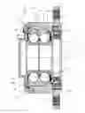
With reference to FIG. 1, an embodiment of the invention is related to a hub-bearing assembly 10 for an agricultural disc, known and consequently not shown. The hub-bearing assembly comprises a rotatable radially outer ring 11, to whom, in a radially external position, a housing 12 is assembled, the housing being made of plastic material and co-molded on the radially outer ring 11. At one end, the housing forms a radial flange 12′ for assembling the disc by means of bolts (not shown), which are screwed in a plurality of threaded metal inserts 13. A double row 14, 15 of rolling bodies 15′ (for example, balls) is interposed between the outer ring 11 and a pair of radially inner rings 16, 17, which are tightly and side by side assembled on a central shaft A, which embossed protrudes from an arm (also not shown) of the frame of the agricultural machine. The inner rings 16, 17 are axially tighten against a shoulder of the shaft A, by means of a nut, which is screwed at the free end of the shaft A. Such an assembly is known and for this reason is not shown in the drawings. At the opposite end, with respect to the end where the housing forms a flange 12′, a closing cap 18 is assembled on the housing 12 and between the housing and the cap a sealing ring 19 is accommodated in a radial and circular groove 20 of the housing 12 and is compressed between the housing 12 and the cap 18, to ensure sealing against contaminants, entering the inner parts of the bearing.
A case sealing device 21 is located at the side of the hub bearing assembly 10, where the agricultural disc is assembled. The sealing device 21 is made of a rotatable portion and a stationary portion.
The invention, according to different embodiments, hereafter described, concerns the use of axial retention means, aimed to improve the grip in the axial direction between the housing 12 and the outer ring, said grip being improved other than what is obtained by means of the radial interference between the plastic housing and the outer ring, in particular between the outer ring surface 110 and the housing surface 120. According to this first embodiment, axial retention means consist in the fact that the outer ring 11 presents two end portions 111, 112, whose correspondent external surfaces 111′, 112′ are located along a radially inner direction with respect to the surface 110. In other words, the outer ring ends are empty in the radial direction towards the shaft A.
During co-molding, in the available volume, part of the housing 12 plastic material will flow and realize two end portions 121, 122, whose respective internal surfaces 121′, 122′ will correspond and exactly fit with the outer ring surfaces 111′ e 112′. In other words, the housing portion 121, 122 will be tooth shaped and will occupy the volume, which is made available by the empty portions 111, 112 of the outer ring. In this way, the engagement of the portions 121, 122 with the emptied outer ring will improve the axial sliding resistance of the housing with respect to the outer ring and vice versa.
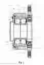
With reference to FIG. 2, an alternative embodiment of the invention concerns the use of only one axial retention means, as the one, which has been described in the previous solution (FIG. 1), and a further retention means, which will be hereafter described. For example, beside the closing cap 18, the axial retention means will be as the one already described: a portion 111 of the outer ring 11 is emptied with respect to the radial dimension of said outer ring and, at the same time, a housing 12 tooth shaped portion 121, which is obtained during co-molding, fills the empty volume, as already described. Instead, on the flange 12′ side, the further retention means is a retention ring 200 which is mounted on the bearing outer ring 11 with radial interference. This retention ring also increases the axial sliding resistance of the bearing with respect to the external co-molded housing. In fact, shape and dimensions of the ring have been optimized to maximize its retention performance. In FIG. 3 a possible embodiment of the retention ring 200 is shown. The ring presents an axi-symmetric geometry and a substantially “L” shaped section. Said “L” shaped section has a substantially radially extended wing 210, which provides the ring with mechanical resistance, since the ring is assembled by radial interference on the bearing outer ring, and a substantially axially extended wing 220. Along the axial direction the ring section is not solid but comprises a first plurality of vanes 230, “U” shaped, and a second plurality of vanes 240, substantially cup shaped. Finally, an axial extended appendix 250 is bent along a radially external direction. In practice, the retention ring increases the axial sliding resistance of the bearing with respect to the housing, thanks to the radial interference between housing and ring. The ring is steadily connected to the plastic housing by means of co-molding, since the liquid plastic can flow inside the two pluralities of vanes 230, 240. The appendix 250, having a radially external inclination, contributes to the increasing of the axial sliding resistance too.
In FIG. 2 it is also clearly shown that the wing 210 of the retention ring 200 acts as a spacer, which separates the outer ring 11 from the sealing device 21. The use of a spacer allows to pre-assemble the sealing device 21 on the bearing, before the housing 12 is co-molded on the outer ring 11. The spacer, in other words the wing 210, which is interposed between the outer ring 11 and the sealing device 21, acts as a barrier against the plastic flow during co-molding and allows a proper closing of the mold, avoiding the direct contact between the sealing device 21 and the outer ring 11. The absence of such a spacer, for example as in the embodiment of FIG. 1, does not allow the co-molding of the sealing device on the bearing and, consequently, does not allow to realize the embodiment of FIG. 1 by means of only one operation.
A third embodiment of the invention is shown in FIG. 4. Such an embodiment comprises a first axial retention means consisting in a retention ring 200, as defined in FIG. 3, and located on the closing cap 18 side. On the flange 12′ side, there is a second axial retention means consisting in the coupling of the portion 112, i.e. the empty portion of the outer ring 11, with the portion 122, i.e. the toothed portion of the plastic housing 12, in other words, the same solution of FIG. 1. Finally, a spacer is used in the form of a ring 400, having a portion 200′, which is similar to the axially extended wing 220 of the ring 200, as previously described, and an appendix 300′, which is similar to the radially extended wing 210 of the ring 200. Said appendix 300′ extends in a radially internal direction and is shaped as a spacer: in fact, the appendix 300′ is dimensionally and functionally equivalent to the spacer, which has been described with reference to FIG. 2.
Finally, a further possible embodiment of the invention is shown in FIG. 5: both on the closing cap side and on the flange side axial retention means are a retention ring 200, as described in FIG. 3.
In the double ring embodiment, the retention rings can present a substantially radially extended wing 210, working as a spacer, which acts as a barrier against the plastic flow during co-molding and allows a proper closing of the mold, avoiding the direct contact between the sealing device 21 and the outer ring 11.
In conclusion, the proposed invention allows to realize the housing co-molding on the bearing, for all possible applications and to increase the axial sliding resistance of the housing with respect to the bearing or vice versa. The use of a co-molded solution allows to obtain better sealing performances, a greater corrosion resistance, since the metal components directly exposed to the external environment are reduced, an easy assembling and a remarkable weight reduction.
Other than the embodiments of the invention, as above disclosed, it is to be understood that a vast number of variations exist. It should also be appreciated that the exemplary embodiment or exemplary embodiments are only examples and are not intended to limit the scope, applicability, or configuration in any way. Rather, the foregoing summary and detailed description will provide those skilled in the art with a convenient road map for implementing at least one exemplary embodiment, it being understood that various changes may be made in the function and arrangement of elements described in an exemplary embodiment without departing from the scope as set forth in the appended claims and their legal equivalents.
Claims
1. A hub-bearing assembly comprising:
a rolling bearing including an outer ring, at least one inner ring, at least one row of rolling bodies and a sealing device;
a housing having an almost annular cylindrical shape, the housing at one end forming a radial flange, containing the rolling bearing and being in direct contact with the bearing outer ring;
a closing cap, assembled on the housing at the opposite end with respect to the one end, where the housing forms the flange, the cap being cup shaped; and
an axial retention feature, which are located along an external surface of the outer ring, said retention means being opposed to the axial sliding of the outer ring with respect to the housing, wherein said axial retention feature comprises a retention ring, which is assembled with radial interference on the bearing outer ring, the retention ring presenting a section, substantially “L” shaped, having a substantially radially extended wing, which provides the ring with mechanical resistance,
wherein the housing is made of plastic material and is co-molded on the outer ring of the rolling bearing,
wherein the substantially radially extended wing separates the outer ring from the sealing device.
2. The hub-bearing assembly according to claim 1, the axial retention feature further comprising at least one housing portion, wherein the housing portion is shaped as a tooth and extends along a radially internal direction, and at least a corresponding outer ring portion, which is emptied along the same radially internal direction and makes available a volume, which is filled by said tooth portion.
3. The hub-bearing assembly according to claim 1, the retention ring further comprising a substantially axially extended wing and a plurality of vanes.
4. The hub-bearing assembly according to claim 1, the retention ring further comprising an axially extended appendix, which is bent along an external radial direction.
Images & Drawings included:


Sources:
- United States Patent and Trademark Office - verify current appl. status at the USPTO↗
Similar patent applications:
- » 10437728
Hub-bearing assembly for a driving wheel of a vehicle, particularly a truck - » 20070012390
Hub-bearing assembly allowing pressurized air to be supplied to the tire of a motor vehicle wheel - » 20080190535
Hub-bearing assembly allowing pressurized air to be supplied to the tyre of a vehicle wheel - » 20100025057
Hub-bearing assembly for soil-working discs - » 20120045155
SEALED HUB-BEARING ASSEMBLY FOR AGRICULTURAL APPLICATIONS - » 20130147258
Integrated hub-bearing assembly for the wheel of a motor vehicle - » 20130292995
Hub-bearing assembly for a motor vehicle wheel - » 20130300187
Hub-bearing assembly for a vehicle wheel - » 20140010489
Hub-bearing assembly with sealing device - » 20140029885
Hub-bearing assembly for rotatably mounting a tilling disc
Recent applications in this class:
- » 20250241223 2025-07-31
DISK DRIVE FOR AGRICULTURAL EQUIPMENT, AND AGRICULTURAL EQUIPMENT - » 20240081169 2024-03-14
DISC ASSEMBLY FOR AN AGRICULTURAL IMPLEMENT - » 20240065133 2024-02-29
GREASELESS GAUGE WHEEL ARM ASSEMBLY - » 20230380324 2023-11-30
PIVOT SYSTEM FOR A ROTATING AGRICULTURAL TOOL - » 20180228076 2018-08-16
Greaseless bushing for agricultural row unit - » 20150327427 2015-11-19
Damping flange for agri-hub - » 20140029885 2014-01-30
Hub-bearing assembly for rotatably mounting a tilling disc - » 20130105185 2013-05-02
Mounting structure for mounting a depth control member to a row unit of an implement - » 20120045155 2012-02-23
SEALED HUB-BEARING ASSEMBLY FOR AGRICULTURAL APPLICATIONS - » 20110162565 2011-07-07
Bushing for mounting a laterally adjustable pivot arm
Recent applications for this Assignee:
- » 20250243936 2025-07-31
SEAL WITH AXIAL AIR VENTS - » 20250043829 2025-02-06
CONDUCTIVE ASSEMBLY WITH REINFORCED BASE PLATE - » 20240405632 2024-12-05
OPTIMIZED BALL BEARING AND METHOD OF DESIGNING AN OPTIMIZED BALL BEARING - » 20240384753 2024-11-21
BEARING ASSEMBLY - » 20240352971 2024-10-24
Rolling-element bearing cage, rolling-element bearing, vehicle, and method for assembling a rolling-element bearing cage - » 20240280141 2024-08-22
BEARING UNIT - » 20240271701 2024-08-15
Self-retaining lip seal - » 20240264656 2024-08-08
SENSOR AND ASSOCIATED METHOD - » 20240255321 2024-08-01
Sensor guard - » 20240200607 2024-06-20
ROLLING-ELEMENT BEARING WITH SEALS AND PURGING CHANNEL