Dispensing closure
US20150225142A1
2015-08-13
14/691,004
2015-04-20
✅ Patent granted
US 9,714,123 B2
2017-07-25
-
-
Patrick M Buechner | Jeremy W Carroll
M&B IP Analysts, LLC
2035-05-10
Abstract:
A dispensing closure for covering an opening of a container including a liquid is presented. The dispensing closure includes an engagement element that fits over the opening of the container and defines a pouring orifice for allowing pouring of the liquid. The pouring orifice having a side defining an air channel for allowing air to flow into the container when liquid during the pouring. The engagement element also includes outer walls and a cap having a hollow including inner walls tightly conforming to the outer walls, a first orifice generally conforming in shape to the pouring orifice, and a second orifice generally conforming in shape to the air channel.
Assignee:
- Agam Innovations Ltd. 3 🇮🇱 Netanya, Israel
Applicant:
Interested in similar patents?
Get notified when new applications in this technology area are published.
Classification:
B65D47/32 » CPC further
Closures with filling and discharging, or with discharging, devices; Closures with discharging devices other than pumps with means for venting
B65D47/12 » CPC main
Closures with filling and discharging, or with discharging, devices; Closures with discharging devices other than pumps with pouring spouts or tubes; with discharge nozzles or passages having removable closures
B65D47/265 » CPC further
Closures with filling and discharging, or with discharging, devices; Closures with discharging devices other than pumps comprising hand-operated members for controlling discharge with slide valves, i.e. valves that open and close a passageway by sliding over a port , e.g. formed with slidable spouts having a rotational or helicoidal movement between planar parts
B65D51/226 » CPC further
Closures not otherwise provided for; Arrangements of closures with protective outer cap-like covers or of two or more co-operating closures; Caps, lids, or covers co-operating with an inner closure arranged to be opened by piercing, cutting, or tearing having means for piercing, cutting, or tearing the inner closure a major part of the inner closure being left inside the container after the opening the piercing or cutting means being non integral with, or not fixedly attached to, the outer closure
B67D1/00 IPC
Apparatus or devices for dispensing beverages on draught
B65D51/22 IPC
Closures not otherwise provided for; Arrangements of closures with protective outer cap-like covers or of two or more co-operating closures; Caps, lids, or covers co-operating with an inner closure arranged to be opened by piercing, cutting, or tearing having means for piercing, cutting, or tearing the inner closure
B65D47/26 IPC
Closures with filling and discharging, or with discharging, devices; Closures with discharging devices other than pumps comprising hand-operated members for controlling discharge with slide valves, i.e. valves that open and close a passageway by sliding over a port , e.g. formed with slidable spouts
Description
CROSS-REFERENCE TO RELATED APPLICATIONS
This application claims the benefit of U.S. Provisional Application No. 61/982,338 filed on Apr. 22, 2014. This application is also a continuation-in-part (CIP) of U.S. patent application Ser. No. 14/589,596 filed on Jan. 5, 2015, now pending, which is a continuation of U.S. patent application Ser. No. 13/252,345 filed on Oct. 4, 2011, now U.S. Pat. No. 8,944,297. The Ser. No. 13/252,345 application claims the benefit of U.S. Provisional Application No. 61/391,101 filed on Oct. 8, 2010. The Ser. No. 13/252,345 application is also a continuation of US Design application No. 29/394,407 filed on Jun. 16, 2011, now U.S. Pat. No. D678,768. All of the applications referenced above are herein incorporated by reference
TECHNICAL FIELD
The present disclosure relates generally to a dispensing closure that is placed on a container for the dispensing of liquid contained therein, and more specifically to a dispensing closure where both an air opening and a liquid opening are sealable or otherwise closeable.
BACKGROUND
A pouring spout is typically attached to a container containing a liquid, for example a bottle, for the purpose of ensuring that the content of the container correctly flows to a target location, for example, a glass. Generally the pouring spout has a dispensing element that is used for the dispensing of the liquid and is generally formed as a tube in some form or shape. The pouring spout further contains an air tube that allows air to enter the container as liquid is dispensed, thereby ensuring uninterrupted flow of the liquid during pouring, as is well known in the art.
When dispensing beverages, a pouring spout is usually either assembled on the bottle or molded thereon for the purpose of making it easier for the user to dispense the beverage quickly and efficiently. Typical pouring spouts known in the art have a flip-top cover to enable closure of the pouring spout for storage purposes. However, such flip-tops increase the height of the containers, thereby increasing material usage and, consequently, costs of production.
It would therefore be advantageous to provide a solution that would overcome the deficiencies of the prior art by providing a dispenser with an effectively sealed pouring spout and an air tube of the pouring spout with a minimal effect on the height of a container.
SUMMARY
A summary of several example embodiments of the disclosure follows. This summary is provided for the convenience of the reader to provide a basic understanding of such embodiments and does not wholly define the breadth of the disclosure. This summary is not an extensive overview of all contemplated embodiments, and is intended to neither identify key or critical elements of all embodiments nor to delineate the scope of any or all aspects. Its sole purpose is to present some concepts of one or more embodiments in a simplified form as a prelude to the more detailed description that is presented later. For convenience, the term “some embodiments” may be used herein to refer to a single embodiment or multiple embodiments of the disclosure.
Some exemplary embodiments disclosed herein include a dispensing closure for covering an opening of a container including a liquid. The dispensing closure comprises an engagement element, wherein the engagement element fits over the opening of the container, the engagement element defining a pouring orifice for allowing pouring of the liquid, the pouring orifice having a side defining an air channel for allowing air to flow into the container when liquid during the pouring the engagement element further comprising: outer walls; and a cap having a hollow including inner walls tightly conforming to the outer walls, a first orifice generally conforming in shape to the pouring orifice, and a second orifice generally conforming in shape to the air channel, wherein the cap is engaged with the engagement element, the cap having a first position about the engagement element where the first orifice is not aligned with the pouring orifice and the second orifice is not aligned with the air channel, the cap having a second position about the engagement element where the first orifice is aligned with the pouring orifice and the second orifice is aligned with the air channel, wherein the liquid cannot be poured when the cap is in the first position and the liquid can be poured when the cap is in the second position.
BRIEF DESCRIPTION OF THE DRAWINGS
The subject matter disclosed herein is particularly pointed out and distinctly claimed in the claims at the conclusion of the specification. The foregoing and other objects, features, and advantages of the disclosed embodiments will be apparent from the following detailed description taken in conjunction with the accompanying drawings.
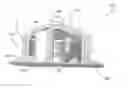
FIG. 1A is a schematic diagram illustrating a side view of a sealed dispensing closure constructed according to an embodiment; and
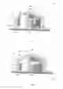
FIG. 1B is a schematic diagram illustrating a side view of an open dispensing closure constructed according to an embodiment.
DETAILED DESCRIPTION
It is important to note that the embodiments disclosed herein are only examples of the many advantageous uses of the innovative teachings herein. In general, statements made in the specification of the present application do not necessarily limit any of the various claimed embodiments. Moreover, some statements may apply to some inventive features but not to others. In general, unless otherwise indicated, singular elements may be in plural and vice versa with no loss of generality. In the drawings, like numerals refer to like parts through several views.
The various disclosed embodiments include a dispensing closure for mounting on a container containing liquid. The dispensing closure comprises an engagement element designed to fit over the opening of the container. The engagement element further comprises a pouring orifice to allow pouring of the liquid. The engagement element further comprises an air channel at a side of the pouring orifice to allow for air to flow into the container when the liquid is poured.
FIG. 1A shows an exemplary and non-limiting schematic diagram illustrating a side view of a dispensing closure 100 in a sealed configuration according to an embodiment. A cap 110 defines a first orifice 120 generally conforming in shape to a pouring orifice 130 of an engagement element 140. In the embodiment shown in FIG. 1A, the cap 110 is in a first position where the first orifice 120 of the cap 110 is not aligned with the corresponding pouring orifice 130 of the engagement element 140. The hollow of the cap 110 has inner walls 115 tightly conforming to outer walls 145 of the engagement element 140 at any rotational position of the cap 110 about the engagement element 140. The engagement element 140 is designed to fit over an opening of a container 150 containing liquids or to be assembled thereto.
The engagement element 140 further includes an air channel 160 which may be beside the pouring orifice 130. The air channel 160 allows air to flow into the container 150 when liquid is poured through the pouring orifice 130. The cap 110 further defines a second orifice 170 generally conforming in shape to the air channel 160. When the cap 110 is in the first position in which the first orifice 120 of the cap 110 is not aligned with the corresponding pouring orifice 130 of the engagement element 140, liquid cannot be poured out of the container through the dispensing closure 100.
FIG. 1B shows an exemplary and non-limiting schematic diagram illustrating a side view of the dispensing closure 100 in an open configuration according to an embodiment. In the embodiment shown in FIG. 1B, the cap 110 is in a second position where the first orifice 120 of the cap 110 is aligned with the corresponding pouring orifice 130 of the engagement element 140. As a result of this configuration, liquid can be poured out of the container through the dispensing closure 100. According to an embodiment, the position of the cap 110 can be changed from the first position where liquid cannot be poured out of the dispensing closure 100 to the second position where liquid can be poured out of the dispensing closure 100 by twisting of the cap 110. As a non-limiting example, the cap 110 may be changed from the first position to the second position upon twisting of the cap 110 by 180 degrees.
According to an embodiment, the container 150 comprises a foil (not shown) affixed to the top of the container 150. The foil may be used to preserve the freshness of the content of the container 150. In a further embodiment, the dispensing closure 100 may further comprise a threaded knife 180. During an initial use, the threaded knife 180 is pressed down upon twisting of the cap 110 from the first position to the second position, thereby perforating the foil and enabling pouring of the liquid from the container 150 thereafter.
A person skilled-in-the-art will readily note that other embodiments may be achieved without departing from the scope of the disclosure. For example and without limitation, other bases and/or engaging elements may be used to affix the dispensing closure 100 to the opening of the container 150.
In an embodiment, the dispensing closure 100 may further include an o-ring (not shown) for sealing the first orifice 120 and/or the second orifice 170. In a further embodiment, the o-ring is affixed to the cap 110. The o-ring placed for, e.g., better sealing. In yet another embodiment, a locking mechanism (not shown) is used to lock the cap 110 in a depressed position when pressed downward. In that embodiment, another press releases the cap to its original locked position.
In an embodiment, the hollow of the cap may be coated with a sealing material layer (not shown) to ensure better sealing. Such a sealing material layer may be, but is not limited to, rubber, Teflon®, or any other appropriate sealing material. In yet another embodiment, motion of the cap may be restricted to the first position, the second position, and positions between the first position and the second position. In an embodiment, a logo, an icon, a text, or the like can be printed, embossed, or otherwise affixed to, e.g., any side of the cap 110.
All examples and conditional language recited herein are intended for pedagogical purposes to aid the reader in understanding the principles of the disclosed embodiment and the concepts contributed by the inventor to furthering the art, and are to be construed as being without limitation to such specifically recited examples and conditions. Moreover, all statements herein reciting principles, aspects, and embodiments of the disclosed embodiments, as well as specific examples thereof, are intended to encompass both structural and functional equivalents thereof. Additionally, it is intended that such equivalents include both currently known equivalents as well as equivalents developed in the future, i.e., any elements developed that perform the same function, regardless of structure.
Claims
What is claimed is:1. A dispensing closure for covering an opening of a container including a liquid, comprising:
an engagement element, wherein the engagement element fits over the opening of the container, the engagement element defining a pouring orifice for allowing pouring of the liquid, the pouring orifice having a side defining an air channel for allowing air to flow into the container when liquid during the pouring the engagement element further comprising:
outer walls; and
a cap having a hollow including inner walls tightly conforming to the outer walls, a first orifice generally conforming in shape to the pouring orifice, and a second orifice generally conforming in shape to the air channel, wherein the cap is engaged with the engagement element, the cap having a first position about the engagement element where the first orifice is not aligned with the pouring orifice and the second orifice is not aligned with the air channel, the cap having a second position about the engagement element where the first orifice is aligned with the pouring orifice and the second orifice is aligned with the air channel, wherein the liquid cannot be poured when the cap is in the first position and the liquid can be poured when the cap is in the second position.
2. The dispensing closure of claim 1, wherein the container includes a top, the dispensing closure further comprising:
a foil affixed to the top.
3. The dispensing closure of claim 2, further comprising:
a threaded knife, wherein the threaded knife perforates the foil when the cap is changed from the first position to the second position.
4. The dispensing closure of claim 1, further comprising:
an o-ring affixed to the cap for sealing at least one of: the first orifice, and the second orifice.
5. The dispensing closure of claim 1, further comprising a sealing material layer, wherein the hollow is coated with the sealing material layer.
6. The dispensing closure of claim 1, further comprising:
a locking mechanism affixed to the cap for locking the cap into any of: the first position, and the second position.
7. The dispensing closure of claim 1, wherein motion of the cap about the engagement element is restricted to between the first position and the second position.
8. The dispensing closure of claim 1, wherein the cap further comprises at least one of: a printed logo on at least one side of the cap, a printed icon on at least one side of the cap, an embossed icon on at least one side of the cap, a printed text on at least one side of the cap, and an embossed text on at least one side of the cap.
Images & Drawings included:
Sources:
- United States Patent and Trademark Office - verify current appl. status at the USPTO↗
Similar patent applications:
- » 20160244215
Dispensing closure, container with a dispensing closure and method for manufacturing a dispensing closure - » 20120187158
Dispensing closure system, flexible package with a dispensing closure system, method of filling the same by a form-fill-seal machine and method of dispensing a flowable product from said package - » 20160264317
Dispensing closure and container with such a dispensing closure - » 20190023463
Dispensing closures and dispensers - » 20190031405
Dispensing closures and dispensers - » 20180148234
Dispensing closures and dispensers - » 20190233180
Dispensing closures and dispensers - » 12204790
Dispensing closure for selectively dispensing material from a multi-chambered container - » 20080245823
Dispensing closure for a container, and dispensing container incorporating same - » 20100288787
Closure system for a container and dispensing closure
Recent applications in this class:
- » 20240270454 2024-08-15
RECEPTACLE CAP - » 20240253872 2024-08-01
FLEXIBLE POUR SPOUT - » 20240150088 2024-05-09
CUP LID - » 20220380094 2022-12-01
Dull Bottle Pour Spout Appratus - » 20220289437 2022-09-15
LIQUID POURING SPOUT - » 20220234792 2022-07-28
DUAL OPENING DISPENSING PACKAGE - » 20200270031 2020-08-27
PORTABLE WATER FILLING SYSTEM FOR A RECREATIONAL VEHICLE - » 20190276198 2019-09-12
DUAL OPENING DISPENSING PACKAGE - » 20180178954 2018-06-28
Construction material tube strap cap - » 20180099790 2018-04-12
Container
Recent applications for this Assignee:
- » 20150122839 2015-05-07
Sealable pourer - » 20120085790 2012-04-12
Sealable pourer