Method and apparatus for providing over-pressure protection for an underground storage cavern
US20150321847A1
2015-11-12
14/464,081
2014-08-20
✅ Patent granted
US 9,359,152 B2
2016-06-07
-
-
Tara M. Pinnock
Justin K. Murray
2034-08-20
Abstract:
A method and apparatus is provided which will provide over-pressure protection for an underground storage cavern by reducing the pressure of a pressurized gas stream originating from the an underground storage cavern to form a lower pressure gas stream, monitoring the pressure of a lower pressure gas stream and stopping the flow of the lower pressure gas stream to the pipeline should the pressure of the lower pressure gas stream exceed a threshold value.
Assignee:
- Air Liquide Large Industries U.S. LP 59 🇺🇸 Houston, TX, United States
Applicant:
Interested in similar patents?
Get notified when new applications in this technology area are published.
Classification:
B01D46/0034 » CPC further
Filters or filtering processes specially modified for separating dispersed particles from gases or vapours with additional separating or treating functions using magnetic forces to remove particles
B01D46/0036 » CPC further
Filters or filtering processes specially modified for separating dispersed particles from gases or vapours with additional separating or treating functions by adsorption or absorption
G01L7/00 » CPC further
Measuring the steady or quasi-steady pressure of a fluid or a fluent solid material by mechanical or fluid pressure-sensitive elements
G01L7/00 » CPC further
Measuring fluid pressure
B01D46/00 IPC
Filters or filtering processes specially modified for separating dispersed particles from gases or vapours
B65G5/00 » CPC main
Storing fluids in natural or artificial cavities or chambers in the earth
B01D53/261 » CPC further
Separation of gases or vapours; Recovering vapours of volatile solvents from gases; Chemical or biological purification of waste gases, e.g. engine exhaust gases, smoke, fumes, flue gases, aerosols,; Drying gases or vapours by adsorption
F17C1/007 » CPC further
Pressure vessels, e.g. gas cylinder, gas tank, replaceable cartridge Underground or underwater storage
B65G43/08 » CPC further
Control devices, e.g. for safety, warning or fault-correcting Control devices operated by article or material being fed, conveyed or discharged
B65G53/30 » CPC further
Conveying materials in bulk through troughs, pipes or tubes by floating the materials or by flow of gas, liquid or foam Conveying materials in bulk through pipes or tubes by liquid pressure
B65G53/58 » CPC further
Conveying materials in bulk through troughs, pipes or tubes by floating the materials or by flow of gas, liquid or foam; Details Devices for accelerating or decelerating flow of the materials; Use of pressure generators
B03C2201/20 » CPC further
Details of magnetic or electrostatic separation Magnetic separation whereby the particles to be separated are in solid form
F17D5/00 » CPC further
Protection or supervision of installations
B01D53/26 IPC
Separation of gases or vapours; Recovering vapours of volatile solvents from gases; Chemical or biological purification of waste gases, e.g. engine exhaust gases, smoke, fumes, flue gases, aerosols, Drying gases or vapours
F16K15/00 » CPC further
Functional types
F16K15/00 » CPC further
Check valves
F17C1/00 IPC
Pressure vessels, e.g. gas cylinder, gas tank, replaceable cartridge
F17C2205/0326 » CPC further
Vessel construction, in particular mounting arrangements, attachments or identifications means; Fluid connections, filters, valves, closure means or other attachments; Fittings, valves, filters, or components in connection with the gas storage device; Valves electrically actuated
F17C2205/0332 » CPC further
Vessel construction, in particular mounting arrangements, attachments or identifications means; Fluid connections, filters, valves, closure means or other attachments; Fittings, valves, filters, or components in connection with the gas storage device; Valves Safety valves or pressure relief valves
F17C2205/0338 » CPC further
Vessel construction, in particular mounting arrangements, attachments or identifications means; Fluid connections, filters, valves, closure means or other attachments; Fittings, valves, filters, or components in connection with the gas storage device Pressure regulators
F17C2221/012 » CPC further
Handled fluid, in particular type of fluid; Pure fluids Hydrogen
F17C2221/013 » CPC further
Handled fluid, in particular type of fluid; Pure fluids Carbone dioxide
F17C2221/016 » CPC further
Handled fluid, in particular type of fluid; Pure fluids Noble gases (Ar, Kr, Xe)
F17C2221/017 » CPC further
Handled fluid, in particular type of fluid; Pure fluids; Noble gases (Ar, Kr, Xe) Helium
F17C2221/031 » CPC further
Handled fluid, in particular type of fluid; Mixtures Air
F17C2223/0123 » CPC further
Handled fluid before transfer, i.e. state of fluid when stored in the vessel or before transfer from the vessel characterised by the phase; Single phase gaseous, e.g. CNG, GNC
F17C2223/035 » CPC further
Handled fluid before transfer, i.e. state of fluid when stored in the vessel or before transfer from the vessel characterised by the pressure level High pressure (>10 bar)
F17C2223/036 » CPC further
Handled fluid before transfer, i.e. state of fluid when stored in the vessel or before transfer from the vessel characterised by the pressure level Very high pressure (>80 bar)
F17C2225/0123 » CPC further
Handled fluid after transfer, i.e. state of fluid after transfer from the vessel characterised by the phase; Single phase gaseous, e.g. CNG, GNC
F17C2225/035 » CPC further
Handled fluid after transfer, i.e. state of fluid after transfer from the vessel characterised by the pressure level High pressure, i.e. between 10 and 80 bars
F17C2250/043 » CPC further
Accessories; Control means; Indicating, measuring or monitoring of parameters; Indicating or measuring of parameters as input values; Parameters indicated or measured Pressure
F17C2250/0443 » CPC further
Accessories; Control means; Indicating, measuring or monitoring of parameters; Indicating or measuring of parameters as input values; Parameters indicated or measured Flow or movement of content
F17C2250/0657 » CPC further
Accessories; Control means; Indicating, measuring or monitoring of parameters; Controlling or regulating of parameters as output values; Parameters; Composition; Humidity Humidity
F17C2270/0152 » CPC further
Applications for fluid transport or storage placed underground; Type of cavity by digging cavities Salt caverns
Y10T137/7837 » CPC further
Fluid handling; Line condition change responsive valves Direct response valves [i.e., check valve type]
B65G53/66 » CPC main
Conveying materials in bulk through troughs, pipes or tubes by floating the materials or by flow of gas, liquid or foam; Details Use of indicator or control devices, e.g. for controlling gas pressure, for controlling proportions of material and gas, for indicating or preventing jamming of material
B03C1/02 » CPC further
Magnetic separation acting directly on the substance being separated
F17C7/00 » CPC further
Methods or apparatus for discharging liquefied, solidified, or compressed gases from pressure vessels, not covered by another subclass
F17C2221/014 » CPC further
Handled fluid, in particular type of fluid; Pure fluids Nitrogen
Y10T137/7842 » CPC further
Fluid handling; Line condition change responsive valves; Direct response valves [i.e., check valve type]; Plural Diverse types
F17C2205/0341 » CPC further
Vessel construction, in particular mounting arrangements, attachments or identifications means; Fluid connections, filters, valves, closure means or other attachments; Fittings, valves, filters, or components in connection with the gas storage device Filters
Description
CROSS-REFERENCE TO RELATED APPLICATION
This patent application is a continuation of U.S. application Ser. No. 14/270,465, filed May 6, 2014, the entire contents of which are incorporated herein by reference.
TECHNICAL FIELD OF THE INVENTION
The present invention relates to a method and apparatus for improving the operational safety in handling a pressurized gas originating from an underground storage cavern.
BACKGROUND OF THE INVENTION
It is known to store hydrogen, as well as other gases in salt caverns. These large storage sites help to provide a buffer in the event when customer demand exceeds normal production capacity or if production capacity is reduced below normal levels. For various reasons, the pressures within these large salt caverns can be very high, sometimes greatly exceeding the pressure of the pipeline to which the gas will be subsequently introduced. One method of controlling the pressure of the gas is to use a pressure control device, which is configured to safely reduce the pressure of the gas before it is introduced to the pipeline. However, if this device were to fail, the overall safety would be compromised. A solution known heretofore has been to include a pressure relief valve downstream the pressure control device, which allows for the system to depressurize to a vent or flare stack. Unfortunately, this solution requires a large capital expenditure as the vent or flare stack must be sized large enough to handle the entire volume of the underground storage cavern.
SUMMARY OF THE INVENTION
Certain embodiments of the present invention relate to a method and apparatus for providing over-pressure protection for an underground storage cavern.
In one embodiment, the method can include the steps of removing the pressurized gas from the underground storage cavern, reducing the pressure of the pressurized gas to form a lower pressure gas, monitoring the pressure of the lower pressure gas, and if the pressure of the lower pressure gas exceeds a first threshold value, sending a signal to a controller to close a set of isolation valves located upstream of a pressure relief valve. By including the set of isolation valves, the size of the vent or flare stack associated with the pressure relief valve can be reduced without compromising safety.
According to other optional aspects of the invention:
-
- the pressurized gas is at a sufficiently high pressure within the underground storage cavern such that the method comprises an absence of an additional pressurization step between removing the pressurized gas from the underground storage cavern and introducing the lower pressure gas to the pipeline;
- the method further includes the step of venting at least a portion of the lower pressure gas to a vent or flare stack via a pressure relief valve if the pressure of the lower pressure gas exceeds a second threshold value;
- the first threshold value and the second threshold value are the same;
- the method further includes the step of removing moisture and/or impurities from the lower pressure gas in downstream equipment before the step of introducing the lower pressure gas to the pipeline;
- the downstream equipment is located downstream the isolation valves and upstream the pipeline;
- the downstream equipment comprises driers configured to remove moisture from the lower pressure gas;
- the downstream equipment comprises filters configured to remove solid particles from the lower pressure gas;
- the first threshold value is based on a pressure rating of the downstream equipment and/or the pipeline; and
- the pressurized gas is selected from the group consisting of nitrogen, natural gas, air, carbon dioxide, hydrogen, helium, argon, and combinations thereof;
In another embodiment of the invention, the apparatus can include a pressure reducing device in fluid communication with the underground storage cavern, a pressure monitor configured to monitor the pressure of the lower pressure gas, at least one isolation valve in fluid communication with the pressure reducing device, and downstream equipment disposed downstream the pressure reducing device, the downstream equipment having a maximum operating pressure. In one embodiment, the pressure reducing device is configured to reduce the pressure of the pressurized gas received from the underground storage cavern to form a lower pressure gas. In another embodiment, the at least one isolation valve is configured to stop the flow of gas if the pressure monitor senses the pressure of the lower pressure gas exceeds a first threshold value.
According to other optional aspects of the invention:
-
- the downstream equipment comprises a water removing device having a pair of desiccant driers configured in a permutable fashion such that one of the driers can be in operation while the other dryer is being regenerated;
- the downstream equipment comprises a particle removal device having a mechanical filtration system having a filter housing, wherein the mechanical filtration system is configured to allow for isolation of the filter housing;
- the particle removal system comprises a magnetic separation system configured to remove fine dust particles based on magnetic properties;
- the first threshold value is based on the maximum operating pressure of the downstream equipment;
- the apparatus further includes a pressure relief valve located downstream the isolation valve, the pressure relief valve configured to send at least a portion of the lower pressure gas to a vent or flare stack if the pressure of the lower pressure gas exceeds a second threshold value; and
- the first threshold value and the second threshold value are the same.
BRIEF DESCRIPTION OF THE DRAWINGS
These and other features, aspects, and advantages of the present invention will become better understood with regard to the following description, claims, and accompanying drawing. It is to be noted, however, that the drawing illustrates only an embodiment of the invention and is therefore not to be considered limiting of the invention's scope as it can admit to other equally effective embodiments.
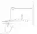
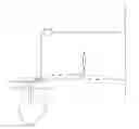
The FIGURE shows a method and apparatus for providing over-pressure protection for an underground storage cavern in accordance with an embodiment of the present invention.
DETAILED DESCRIPTION
While the invention will be described in connection with several embodiments, it will be understood that it is not intended to limit the invention to those embodiments. On the contrary, it is intended to cover all the alternatives, modifications and equivalence as may be included within the spirit and scope of the invention defined by the appended claims.
High pressure gases, including, but not limited to: nitrogen, air, carbon dioxide, hydrogen, helium, and argon, can be stored in caverns, whether leached in salt formations or created by hard rock mining. Additionally, the pressure of these gases exiting the cavern can be at very high pressures (e.g., 100-200 atmospheres), which can cause safety issues for downstream equipment and the mechanical integrity of the pipeline.
Now turning to the FIGURE. The gas is withdrawn from pipeline 2 via line 4 and compressed in compressor 5 to a pressure that is sufficiently high enough such that the gas can be removed from underground storage cavern 10 without any mechanical means (e.g., pumps, etc. . . . ), preferably to a pressure of 10 atmospheres or higher, more preferably to 100-200 atmospheres. Following compression, the gas travels via line 6. When pressure control device 14 is in a closed position, the gas is then directed into underground storage cavern 10. The flow rate of the gas going in and out of underground storage cavern can be monitored by flow indicator 12.
When it is desired to use gas from underground storage cavern 10, pressure control device 14 is opened, which allows for the gas to expand across pressure control device 14 before heading to downstream equipment 16, which can include equipment for moisture removal and/or removal of any unwanted impurities (e.g., solid particles, magnetic particles, unwanted gases) before being introduced back to pipeline 2.
In one embodiment of the invention, an over-pressurization system can be installed should pressure control device 14 fail to safely control the pressure of the gas for the downstream equipment 16 and pipeline 2. The pressure of the gas following pressure control device 14 can be monitored by pressure indicator 15. Pressure relief valve 18 can be installed downstream pressure control device 14 in order to de-pressurizes the system to a vent or flare stack 19 in the event that the monitored pressure is too high. In the embodiment shown, isolation valves 8 are included, preferably both upstream and downstream of pressure control device 14, which help to reduce the height of the vent or flare stack and provide additional safety protection.
In one embodiment, isolation valves 8 would be closed if the pressure of the lower pressure gas (i.e., gas downstream of pressure control device 14) as measured by pressure indicator 15 is above a certain operational threshold (e.g., close to or just below the pressure rating of downstream equipment 16 and pipeline 2). In one embodiment, pressure indicator 15 is in electronic communication with isolation valves 8, either directly or through a controller (not shown), such that pressure indicator 15 is configured to send a signal to isolation valves 8 to close. In one embodiment, pressure relief valve 18 and vent or flare stack can be included to provide over-pressure protection until isolation valves 8 are closed. In one embodiment, since the design of pressure relief valve 18 is primarily to provide over-pressure protection until the isolation valves are closed, pressure relief valve 18 can be smaller and the vent or flare stack height can be reduced due to the reduced thermal radiation.
In one embodiment, the pressure of the gas in the cavern is maintained above the pipeline pressure. This advantageously allows for the absence of a mechanical device to help with movement of the gas to the pipeline (e.g., no need for an additional pump to move the gas from the storage cavern to the pipeline).
While the invention has been described in conjunction with specific embodiments thereof, it is evident that many alternatives, modifications, and variations will be apparent to those skilled in the art in light of the foregoing description. Accordingly, it is intended to embrace all such alternatives, modifications, and variations as fall within the spirit and broad scope of the appended claims. The present invention may suitably comprise, consist or consist essentially of the elements disclosed and may be practiced in the absence of an element not disclosed. Furthermore, language referring to order, such as first and second, should be understood in an exemplary sense and not in a limiting sense. For example, it can be recognized by those skilled in the art that certain steps or devices can be combined into a single step/device.
The singular forms “a”, “an”, and “the” include plural referents, unless the context clearly dictates otherwise.
“Comprising” in a claim is an open transitional term which means the subsequently identified claim elements are a nonexclusive listing i.e. anything else may be additionally included and remain within the scope of “comprising.” “Comprising” is defined herein as necessarily encompassing the more limited transitional terms “consisting essentially of” and “consisting of”; “comprising” may therefore be replaced by “consisting essentially of” or “consisting of” and remain within the expressly defined scope of “comprising”.
“Providing” in a claim is defined to mean furnishing, supplying, making available, or preparing something. The step may be performed by any actor in the absence of express language in the claim to the contrary.
Optional or optionally means that the subsequently described event or circumstances may or may not occur. The description includes instances where the event or circumstance occurs and instances where it does not occur.
Ranges may be expressed herein as from about one particular value, and/or to about another particular value. When such a range is expressed, it is to be understood that another embodiment is from the one particular value and/or to the other particular value, along with all combinations within said range.
All references identified herein are each hereby incorporated by reference into this application in their entireties, as well as for the specific information for which each is cited.
Claims
1. A method for providing over-pressure protection for an underground storage cavern, the method comprising the steps of:
removing a pressurized gas from the underground storage cavern;
reducing the pressure of the pressurized gas to form a lower pressure gas;
monitoring the pressure of the lower pressure gas;
introducing the lower pressure gas a pipeline if the pressure of the lower pressure gas is below a first threshold value; and
closing an isolation valve upstream of a pressure relief valve if the pressure of the lower pressure gas is at or exceeds the first threshold value such that the flow of the lower pressure gas to the pipeline is stopped.
2. The method as claimed in claim 1, wherein the pressurized gas is at a sufficiently high pressure within the underground storage cavern such that the method comprises an absence of an additional pressurization step between removing the pressurized gas from the underground storage cavern and introducing the lower pressure gas to the pipeline.
3. The method as claimed in claim 1, further comprising the step of venting at least a portion of the lower pressure gas to a vent or flare stack via the pressure relief valve if the pressure of the lower pressure gas exceeds a second threshold value.
4. The method as claimed in claim 3, wherein the first threshold value and the second threshold value are the same.
5. The method as claimed in claim 1, further comprising the step of removing moisture and/or impurities from the lower pressure gas in downstream equipment before the step of introducing the lower pressure gas to the pipeline.
6. The method as claimed in claim 5, wherein the downstream equipment is located downstream the isolation valves and upstream the pipeline.
7. The method as claimed in claim 5, wherein the downstream equipment comprises driers configured to remove moisture from the lower pressure gas.
8. The method as claimed in claim 5, wherein the downstream equipment comprises filters configured to remove solid particles from the lower pressure gas.
9. The method as claimed in claim 5, wherein the first threshold value is based on a pressure rating of the downstream equipment and/or the pipeline.
10. The method as claimed in claim 1, wherein the pressurized gas is selected from the group consisting of nitrogen, natural gas, air, carbon dioxide, hydrogen, helium, argon, and combinations thereof.
11. (canceled)
12. (canceled)
13. (canceled)
14. (canceled)
15. (canceled)
16. (canceled)
17. (canceled)
18. The method as claimed in claim 1, wherein the underground storage cavern is a salt cavern.
19. The method as claimed in claim 1, wherein the pressurized gas is hydrogen.
Images & Drawings included:
Sources:
- United States Patent and Trademark Office - verify current appl. status at the USPTO↗
Similar patent applications:
Recent applications in this class:
- » 20250206539 2025-06-26
METHOD OF ENHANCING EFFICIENCY OF GEOMECHANICAL ENERGY STORAGE SYSTEMS - » 20250206538 2025-06-26
STORING AND MANUFACTURING HYDROGEN IN HORIZONTALLY DRILLED WELLS - » 20250033886 2025-01-30
HYDROGEN GAS SUBSURFACE STORAGE (HSS) - » 20240425285 2024-12-26
NATURAL HYDROGENATION OF AN ORGANIC CARRIER AT UPSTREAM CONDITIONS - » 20240246767 2024-07-25
RAINWATER STORAGE DEVICE AND CONSTRUCTION METHOD THEREOF - » 20230294920 2023-09-21
METHOD TO ENHANCE SUBSURFACE GAS STORAGE IN SALT CAVERNS - » 20230257202 2023-08-17
HYDROGEN GAS SUBSURFACE STORAGE (HSS) - » 20230092034 2023-03-23
Underground energy storage systems - » 20230009233 2023-01-12
Method for the regulation of an installation for the geological sequestration of carbon dioxide, suitable for renewable energy supply - » 20220402700 2022-12-22
Subterranean energy storage system
Recent applications for this Assignee:
- » 20230350437 2023-11-02
Method for controlling the velocity of a pipeline pig - » 20220040705 2022-02-10
Magnetic Ljungstrom filter - » 20200256740 2020-08-13
Apparatus for installing a thermocouple inside a reactor tube filled with catalyst - » 20200256739 2020-08-13
Method for installing a thermocouple inside a reactor tube filled with catalyst - » 20200254413 2020-08-13
Apparatus for installing a thermocouple inside a reactor tube filled with catalyst - » 20200254412 2020-08-13
Method for installing a thermocouple inside a reactor tube filled with catalyst - » 20180156343 2018-06-07
Automatic pressure and vacuum clearing skid - » 20170314736 2017-11-02
Nitrogen pumping from a tank truck - » 20160355341 2016-12-08
Cavern pressure management - » 20160138735 2016-05-19
Materials of construction for use in high pressure hydrogen storage in a salt cavern