Transportation of a direct drive generator
US20150361963A1
2015-12-17
14/655,481
2013-12-23
✅ Patent granted
US 10,145,362 B2
2018-12-04
WO; PCT/EP2013/077872; 20131223
WO; WO2014/106601; 20140710
Jun Yoo
Schmeiser, Olsen & Watts, LLP
2035-03-04
Abstract:
A method of handling a direct drive generator of a wind turbine is provided. The direct drive generator comprises a stator and a rotor concentrically arranged about an axis of the direct drive generator. The method includes steps of placing the direct drive generator on a support structure, fixing a selected one of the stator or the rotor to the support structure, connecting actuator means to a remaining one of the stator or the rotor, and rotating the remaining one of the stators or the rotor using the actuator means.
Inventors:
- Uffe Eriksen 30 🇩🇰 Horsens, Denmark
- PEDER HYKKELBJERG HANSEN 1 🇩🇰 SILKEBORG, Denmark
- HENRIK ANTON JENSEN 1 🇩🇰 IKAST, Denmark
Assignee:
- Siemens Aktiengesellschaft 315 🇩🇪 , Germany
Applicant:
Interested in similar patents?
Get notified when new applications in this technology area are published.
Classification:
F03D1/00 IPC
Wind motors with rotation axis substantially parallel to the air flow entering the rotor
F03D9/00 IPC
Adaptations of wind motors for special use; Combinations of wind motors with apparatus driven thereby; Wind motors specially adapted for installation in particular locations
F03D80/82 » CPC further
Details, components or accessories not provided for in groups -; Arrangement of components within nacelles or towers of electrical components
F05B2220/7066 » CPC further
Application in combination with an electrical generator via a direct connection, i.e. a gearless transmission
H02K15/00 » CPC further
Methods or apparatus specially adapted for manufacturing, assembling, maintaining or repairing of dynamo-electric machines
F03D80/88 » CPC further
Details, components or accessories not provided for in groups -; Arrangement of components within nacelles or towers of mechanical components
F03D80/80 IPC
Details, components or accessories not provided for in groups - Arrangement of components within nacelles or towers
Y10T29/49828 » CPC further
Metal working; Method of mechanical manufacture; Assembling or joining Progressively advancing of work assembly station or assembled portion of work
B64C27/00 IPC
Aircraft kinds and components not otherwise provided for
B64C27/00 IPC
Rotorcraft; Rotors peculiar thereto
F03D15/20 » CPC further
Transmission of mechanical power Gearless transmission, i.e. direct-drive
F03D13/10 » CPC further
Assembly, mounting or commissioning of wind motors; Arrangements specially adapted for transporting wind motor components Assembly of wind motors; Arrangements for erecting wind motors
F03D9/25 » CPC further
Adaptations of wind motors for special use; Combinations of wind motors with apparatus driven thereby; Wind motors specially adapted for installation in particular locations; Wind motors characterised by the driven apparatus the apparatus being an electrical generator
F03D13/40 » CPC further
Assembly, mounting or commissioning of wind motors; Arrangements specially adapted for transporting wind motor components Arrangements or methods specially adapted for transporting wind motor components
Description
CROSS-REFERENCE TO RELATED APPLICATIONS
This application claims priority to PCT Application No. PCT/EP2013/077872 having a filing date of Dec. 23, 2013, based off of EP 13150378.1 having a filing date of Jan. 7, 2013, the entire contents of which are hereby incorporated by reference.
FIELD OF TECHNOLOGY
The following relates to a method of handling a direct drive generator of a wind turbine and an assembly for handling a direct drive generator of a wind turbine.
BACKGROUND
With the increasing demand for renewable energies the typical rated output powers of wind turbines have been growing for many years. The greater output power leads to corresponding increases in the size and weight of the various parts of the wind turbines. Thus, transportation of the parts of the wind turbines has become increasingly difficult. It has been found that rotatable parts of the wind turbines such as bearing may be damaged during transport or storage because of the enormous weight of the individual components. The damage typically shows as stand still marks where the weight of one component causes deformations to itself or an underlying part. One such part of a wind turbine that may be difficult to handle is a direct drive generator.
SUMMARY
An aspect relates to a method of handling a direct drive generator of a wind turbine. The direct drive generator comprises a stator and a rotor concentrically arranged about an axis of the direct drive generator. The method includes steps of:
placing the direct drive generator on a support structure;
fixing a selected one of the stator or the rotor to the support structure;
connecting actuator means to a remaining one of the stator or the rotor; and
rotating the remaining one of the stator or the rotor using the actuator means.
Embodiments of the invention avoid stand still marks by constantly moving or rotating the inner part of the direct drive generator during handling. It should be noted that “rotating” does not necessarily mean rotating the inner part of the direct drive generator by one or more complete revolutions but also motions over only a segment of a circle, e.g. forth and back movements. For example, the outer part of the direct drive generator may rest on the support structure and thereby effectively shields the inner part from any contact with the support structure which may cause damages to the inner part. In this case, the inner part of the direct drive generator will be rotated during handling. Furthermore, since the outer part of the direct drive generator does not move relative to the support structure, the outer part will not be damaged either. Thus, the inventive method protects the direct drive generator against damages from stand still marks and from impacts during handling. In addition, health and safety risks are eliminated by rotating the inner one of the stator or the rotor because the rotating parts are embedded by the outer one of the stator or the rotor which is fixed to the support structure.
However, in another preferred embodiment of the method of the invention, inner one of the rotor or the stator is fixed to the support structure while the outer one of the rotor or the stator is rotated during handling. The inner one of the rotor or the stator may be fixed to the support structure by means of a flange or the like that is accessible from the outside of the direct drive generator. The inner one of the rotor or the stator may be propped holding the direct drive generator in such a way that the outer one of the rotor or the stator may be rotated without the support structure interfering. Rotating the outer one is especially useful if the outer one is the rotor of the direct drive generator and the inner one is the stator because the rotor is designed for rotating while the stator may comprise ports or connectors for lubricants for a bearing of the direct drive generator which may be connected to a lubricant reservoir and/or pump included in the support structure. Furthermore, rotating the outer one (e.g. rotor of the direct drive generator) is especially useful when the direct drive generator is already installed within a nacelle of a wind turbine and the direct drive generator and the nacelle are handled together. The nacelle effectively shields the rotor which means that the rotor cannot be damaged or cause damage or harm when rotating during handling.
Preferably, selected one of the stator or the rotor is the stator of the direct drive generator and the remaining one of the stator or the rotor is the rotor of the direct drive generator. The advantage is that the rotor of the direct drive generator is designed for rotation anyway and, as already mentioned above, the stator may comprise ports and connectors that may be connected to suitable means in the support structure used during handling. Furthermore, the direct drive generator may be handled together with a hub connected to it. In such a case the step of connecting actuator means to the rotor can be carried out by connecting the actuator means to the hub in such a way that the rotor will be rotated by means of rotating the hub.
Preferably, the remaining one of the stator or the rotor is rotated back and forth. As already explained above, such smaller movements are sufficient for avoiding stand still marks. However, rotating the remaining part of the direct drive generator back and forth can be accomplished by less complex means such as a hydraulic cylinder which can expand and contract. The linear motion of the hydraulic cylinder will then be transformed into a rotational movement by the inner part of the direct drive generator. Furthermore, only a relatively small extension and contraction of the actuator means/hydraulic cylinder will be required for a back and forth motion as compared to rotating the remaining one by a plurality of full rotations during handling.
The step of rotating may include rotating the remaining one of the stator or the rotor during a first time interval and not rotating the remaining one of the stator or the rotor during a second time interval following the first time interval. This procedure can be repeated such that the remaining one of the stator or the rotor is periodically moved thus avoiding stand still marks, for example, the remaining one of the stator or the rotor can be rotated for some seconds every ten minutes thus reducing power consumption. The length of the time intervals can be chosen depending on the situation. For example, the rotation can be constantly carried out during e.g. transportation by train while it may be carried out in intervals while being transported on a truck. Furthermore, the length of the time intervals can be chosen depending on the availability of an external power supply for the actuator means, i.e. rotation may be carried out constantly or with relatively shorter pauses when such a power supply is available and with relatively longer pauses when such a power supply is unavailable.
The method may further comprise connecting the actuator means to the support structure. The connection to the support structure provides a pivotal point for the actuator means.
The method may further comprise hoisting the support structure with the direct drive generator onto transportation means. The support structure may then be transported together with the direct drive generator while rotating the inner one of the stator or the rotor. Alternatively, the support structure may be stored together with the direct drive generator while rotating the inner one of the stator or the rotor. Transportation and storing are the most relevant ways of handling the direct drive generator.
A second aspect of the invention relates to an assembly for handling a direct drive generator of a wind turbine. The direct drive generator comprises a stator and a rotor concentrically arranged about an axis of the direct drive generator. The assembly includes a support structure adapted to carry the direct drive generator and actuator means adapted to rotate one of the stator or the rotor of the direct drive generator.
In a preferred embodiment of the invention, the actuator means are connected to the support structure. Preferably the actuator means comprise a hydraulic cylinder.
BRIEF DESCRIPTION
Some of the embodiments will be described in detail, with reference to the following figures, wherein like designations denote like members, wherein:
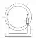
FIG. 1 shows a direct drive generator arranged on a support structure according to a first embodiment.
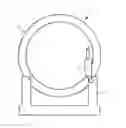
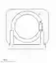
FIG. 2 shows a direct drive generator installed within a nacelle arranged on a support structure according to a second embodiment.
DETAILED DESCRIPTION
FIG. 1 shows a direct drive generator 1 arranged on a support structure 4. An outer rotor 3 of the direct drive generator 1 is fixed to the support structure 4 for handling. Thus, the outer rotor 3 cannot move relatively to the support structure 4 thereby avoiding damages to the outer rotor 3 such as scratch marks. Actuator means 5, e.g. a hydraulic cylinder, are connected to an inner stator 2 of the direct drive generator 1. The actuator means 5 of the embodiment shown in FIG. 1 could also be connected to the outer rotor 3 instead of the support structure 4, however, connection of the actuator means 5 to the support structure 4 is preferred because the support structure 4 provides more space for suitable connection means than the relatively thin rim of the outer rotor 3. The actuator means 5 rotate the inner stator 2 relatively to the outer rotor 3 to avoid the generation of stand still marks. The invention may be equally used for direct drive generators having an outer stator and an inner rotor. In this case a first end of the actuator means 5 will connect to the inner rotor and a second end of the actuator means 5 will connect to the outer stator or the support means 4.
FIG. 2 shows a direct drive generator 1 installed within a nacelle 6 arranged on a support structure 4 which are handled according to a second embodiment of the method of the invention. Here the actuator means 5 are connected to the outer rotor 3 of the direct drive generator 1. The inner stator 2 may be fixed to the support structure 4. For example, the inner stator 2 may be fastened to the support structure 4 by means of nuts and bolts that extend through corresponding borings in the support structure 4 and a flange of the inner stator 2. The nacelle 6 may rest on the support structure 4 or may be affixed to it.
The invention has an advantage that handling of the direct drive generator 1 e.g. for storing or transportation does not cause any damages to the direct drive generator 1.
The present invention has been described with respect to exemplary embodiments thereof which serve as illustrative examples of the invention. However, although specific embodiments have been described to explain the invention, deviations from these embodiments are possible. Hence, the scope of the invention shall not be limited by the described exemplary embodiments but only by the appended claims.
Claims
1. A method of handling a direct drive generator of a wind turbine, the direct drive generator comprising a stator and a rotor concentrically arranged about an axis of the direct drive generator, wherein the method comprises:
placing the direct drive generator on a support structure;
fixing a selected one of the stator or the rotor to the support structure;
connecting actuator means to a remaining one of the stator or the rotor; and
rotating the remaining one of the stator or the rotor using the actuator means.
2. The method of the claim 1, wherein the selected one of the stator or the rotor is an inner one of the stator or the rotor and wherein the remaining one of the stator or the rotor is an outer one of the stator or the rotor.
3. The method of claim 1, wherein the selected one of the stator or the rotor is the stator of the direct drive generator and wherein the remaining one of the stator or the rotor is the rotor of the direct drive generator.
4. The method of claim 1, wherein the remaining one of the stator or the rotor is rotated back and forth.
5. The method of claim 1, wherein the step of rotating includes rotating the remaining one of the stator or the rotor during a first time interval and not rotating the remaining one of the stator or the rotor during a second time interval following the first time interval.
6. The method of claim 1, further comprising connecting the actuator means to the support structure.
7. The method of claim 1, further comprising hoisting the support structure with the direct drive generator onto a transportation means.
8. The method of claim 2, wherein the support structure is transported together with the direct drive generator while rotating the inner one of the stator or the rotor.
9. The method of claim 2, wherein the support structure is stored together with the direct drive generator while rotating the inner one of the stator or the rotor.
10. An assembly for handling a direct drive generator of a wind turbine, the direct drive generator comprising a stator and a rotor concentrically arranged about an axis of the direct drive generator, the assembly including a support structure configured to carry the direct drive generator and an actuator means configured to rotate one of the stator or the rotor of the direct drive generator.
11. The assembly of claim 10, wherein the actuator means are connected to the support structure.
12. The assembly of one of the claim 10, wherein the actuator means comprise a hydraulic cylinder.
Images & Drawings included:
Sources:
- United States Patent and Trademark Office - verify current appl. status at the USPTO↗
Recent applications in this class:
- » 20160230744 2016-08-11
WIND TURBINE WITH DUAL BLADE ASSEMBLIES - » 20160076522 2016-03-17
WIND TURBINE ARCHITECTURE - » 20150322922 2015-11-12
GENERATOR WITH STATOR SUPPORTED ON ROTOR
Recent applications for this Assignee:
- » 20230394331 2023-12-07
Method for computer-implemented determination of a data-driven prediction model - » 20200175031 2020-06-04
Device and method for coupling a machine to a plurality of applications - » 20190370332 2019-12-05
Semantic textual similarity system - » 20190334891 2019-10-31
Retrieval device for authentication information, system and method for secure authentication - » 20190317733 2019-10-17
Method and tool for system development - » 20190075027 2019-03-07
Method and apparatus for determining a network topology of a hierarchical network - » 20190069455 2019-02-28
Method and apparatus for assigning assemblies to component fitting lines - » 20190064761 2019-02-28
Control of a water supply network - » 20190047108 2019-02-14
Apparatus for shortening the rotor blades of a turbomachine - » 20180373214 2018-12-27
Method for operating an automation component