Wire branch structure
US20150366106A1
2015-12-17
14/763,843
2014-01-20
✅ Patent granted
US 9,414,533 B2
2016-08-09
WO; PCT/JP2014/050910; 20140120
WO; WO2014/119404; 20140807
Sherman Ng
Mots Law, PLLC
2034-01-20
Abstract:
A wire branch structure (1) includes a plurality of wires (3) and a shield member (5) which covers the circumference of the wires (3). One end side of each of the wires (3) is inserted in a main line side shell (7). The other end side of each of the wires (3) is branched from the main line side shell (7) and is inserted into branch line side shells (9, 11) respectively. An isolation part (15) is provided in the shield member (5), which isolates the wires (3) adjacent to a branch part (13) in which the other end side of each of the wires (3) is inserted in the branch line side shells (9, 11) respectively and branched.
Assignee:
- Yazaki Corporation 5,523 🇯🇵 Tokyo, Japan
Applicant:
Interested in similar patents?
Get notified when new applications in this technology area are published.
Classification:
H01B7/0045 » CPC further
Insulated conductors or cables characterised by their form Cable-harnesses
H01B7/00 IPC
Insulated conductors or cables characterised by their form
H01B11/06 IPC
Communication cables or conductors; Cables with twisted pairs or quads with means for reducing effects of electromagnetic or electrostatic disturbances, e.g. screens
H02G3/04 IPC
Installations of electric cables or lines in or on buildings, equivalent structures or vehicles; Details Protective tubings or conduits or channels or other supports
H02G3/0487 » CPC further
Installations of electric cables or lines in or on buildings, equivalent structures or vehicles; Details; Protective tubings or conduits or channels or other supports; Tubings, i.e. having a closed section with a non-circular cross-section
H01R4/00 IPC
Electrically-conductive connections between two or more conductive members in direct contact, i.e. touching one another; Means for effecting or maintaining such contact; Electrically-conductive connections having two or more spaced connecting locations for conductors and using contact members penetrating insulation
H01B9/02 IPC
Power cables with screens or conductive layers, e.g. for avoiding large potential gradients
H05K9/00 » CPC main
Screening of apparatus or components against electric or magnetic fields
H05K9/00 » CPC main
Screening of apparatus or components against electric or magnetic fields
H01R9/03 IPC
Structural associations of a plurality of mutually-insulated electrical connecting elements, e.g. terminal strips or terminal blocks; Terminals or binding posts mounted upon a base or in a case; Bases therefor Connectors arranged to contact a plurality of the conductors of a multiconductor cable, e.g. tapping connections
H01R31/06 » CPC further
Coupling parts supported only by co-operation with counterpart Intermediate parts for linking two coupling parts, e.g. adapter
Description
TECHNICAL FIELD
The present invention relates to a wire branch structure.
BACKGROUND
As a conventional wire branch structure, one including a plurality of wires and a shield member that covers a circumference of the wires is known, in which one end sides of the wires are inserted in an inlet side cylinder body, and the other end sides of the wires are branched from the inlet side cylinder body and inserted into two outlet side cylinder bodies (refer to PTL 1).
This conventional wire branch structure is applied to connections between inverters and motor generators for example, and one end sides of the wires inserted in the inlet side cylinder body are connected to the inverters and the other ends of the wires inserted in the outlet side cylinder bodies are connected to two motor generators respectively.
By covering the circumference of the wires arranged as such with a shield member, penetration or leakage of noise or the like can be prevented.
CITATION LIST
Patent Literature
PTL 1: JP 2012-084275 A
SUMMARY
However, in the conventional wire branch structure, since the wires are covered by the same shield member in a lump, there was a possibility that an electromagnetic interference may occur to adjacent wires at a branch part of the wires which are inserted into the separate outlet side cylinder bodies and branched.
Therefore, an object of the present invention is to provide a wire branch structure which can prevent an electromagnetic interference of wires at a branch part of a plurality of wires.
A wire branch structure according to an aspect of the present invention includes a plurality of wires and a shield member that covers a circumference of the wires. One end side of each of the wires is inserted in a main line side shell. The other end side of each of the wires is respectively inserted in two or more branch line side shells that are branched from the one member side. The shield member is provided with one or more isolation parts that isolate the wires which are adjacent to a branch part in which the other end side of each of the wires is respectively inserted in the branch line side shells and branched.
By making the shield member provided with one or more isolation parts that isolate the wires which are adjacent to a branch part in which the other end side of each of the wires is respectively inserted in the branch line side shells and branched, an electromagnetic interference of the adjacent wires at the branch part of the wires can be prevented.
Each of the isolation parts is preferably formed by joining opposing parts of an inner circumference surface of the shield member.
By forming each of the isolation parts by joining opposing parts of an inner circumference surface of the shield member, the isolation parts can be provided without increasing the number of component parts.
According to the aspect of the present invention, an effect of being able to provide a wire branch structure which can prevent an electromagnetic interference of the wires at a branch part of a plurality of wires can be obtained.
BRIEF DESCRIPTION OF DRAWINGS
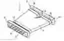
FIG. 1 is a top view of a wire branch structure according to an embodiment.
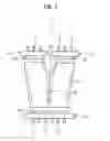
FIG. 2 is a partially sectional view of the wire branch structure according to the embodiment.
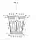
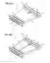
FIG. 3(a) is a perspective view in which a shield member of the wire branch structure according to the embodiment is assembled; and FIG. 3(b) is a perspective view in which an isolation part is provided to the shield member of the wire branch structure according to the embodiment.
DESCRIPTION OF EMBODIMENTS
By referring to FIGS. 1 to 3, a wire branch structure according to an embodiment of the present invention will be explained.
A wire branch structure 1 according to the embodiment includes a plurality of wires 3 and a shield member 5 that covers the circumference of the wires 3. One end side (main line side) of each of the wires 3 is inserted into a main line side ring 7. The other end side (branch line side) of each of the wires 3 is respectively inserted into two branch line side shells 9, 11 which are branched from the main line side shell 7.
The shield member 5 includes an isolation part 15 which mutually isolates wires 3 which are adjacent to a branch part 13 in which the other end side of each of the wires 3 is respectively inserted into the branch line side shells 9, 11 and branched.
The isolation part 15 is formed by joining opposing parts of an inner circumference surface of the shield member 5.
As illustrated in FIGS. 1 to 3, the plurality of (six here) wires 3 are arranged in parallel, and an insulation coating is peeled from both ends of each wire and the conductor part is made as terminals. In addition, the ends of the wires 3 may not be made as terminals, but terminals may be connected to the conductor parts by crimping or the like instead.
In the embodiment, at one end side of each of the wires 3, all of the wires 3 are inserted into the shell 7, and the other end sides of the wires 3 are branched at the branch part 13 such that three wires form one set, and each set (two sets here) is inserted into a separate branch line side shell 9, 11 respectively.
The main line side shell 7 into which the one end side of each of the wires 3 is inserted is composed of an electrically conductive material and is assembled to a connector housing (not illustrated) which is fitted to an inverter side connector (not illustrated), for example. A main line side cylindrical part 17 into which the one end side of each of the wires 3 is inserted is provided at the main line side shell 7.
The branch line side shells 9, 11 into which the other end side of each of the wires 3 is inserted are composed of an electrically conductive material and are assembled to respective connector housings (not illustrated) which are fitted to respective connectors (not illustrated) on the two motor generator side, for example. Branch line side cylindrical parts 19, 21 into which the other end side of each of the wires 3 is inserted respectively are provided at the branch line side shells 9, 11.
One end of the shield member 5 is assembled to an outer circumference of the main line side cylindrical part 17 of the main line side shell 7, and the other end of the shield member 5 is assembled to the outer circumferences of the branch line side cylindrical parts 19, 21 of the branch line side shells 9, 11.
The shield member 5 is composed of a mesh shaped braided conductor in which an electrically conductive material is braided, or an electrically conductive metallic foil formed into a sheet shape, and is formed to have a cylindrical shape with the side of its branch line side shells 9, 11 (the other end side) branched into a fork. The shield member 5 may also be simply formed into a cylindrical shape without forming the side of the branch line side shells 9, 11 (the other end side) into a fork.
The shield member 5 covers the circumference of the wires 3 arranged between the main line side shell 7 and the branch line side shells 9, 11, and is assembled to the outer circumference of the main line side cylindrical part 17 of the main line side shell 7 at its one end, and is assembled to the outer circumferences of the branch line side cylindrical parts 19, 21 of the branch line side shells 9, 11 at its other end.
The shield member 5 is fixed at its assembly parts with the main line side cylindrical part 17 of the main line side shell 7 and with the branch line side cylindrical parts 19, 21 of the branch line side shells 9, 11 by fixing members such as crimping rings (not illustrated), and is electrically connected to the main line side shell 7 and the branch line side shells 9, 11 to form a shield circuit that prevents penetration or leakage of noise and the like on the wires 3.
The shield member 5 that covers the circumference of the wires 3 is provided with the isolation part 15 which mutually isolates the adjacent wires 3 at the branch part 13 in which the other end side of each of the wires 3 is inserted respectively into the branch line side shells 9, 11 and branched. The isolation part 15 is composed by joining opposing parts of an inner circumference surface of the shield member 5 by a jointing method such as welding.
Since the sets of the wires 3 that are separated by the isolation part 15 are connected to separate motor generators respectively, signals that have completely different properties are flowing. Therefore, by isolating with the isolation part 15, an electromagnetic interference of the adjacent wires 3 can be prevented and malfunction of the motor generators can be prevented.
Further, since the isolation part 15 is constructed by joining the shield member 5, it is not necessary that the branched wires 3 are covered independently with separate shield members 5, and the connection of the shield with the main line side shell 7 at one end of the shield member 5 can be done in one place, while a shielding effect similar to when separate shield members 5 are arranged can be obtained. In addition, since it is not necessary that a crimping member such as a clip is used, the number of component parts can be reduced.
In an assembly method of the wire branch structure 1, first, one end side of each of the wires 3 is inserted into the main line side shell 7. Next, one end of the shield member 5 is assembled to an outer circumference of the main line side cylindrical part 17 of the main line side shell 7. Subsequently, the other end side of each of the wires 3 is inserted into the branch line side cylindrical parts 19, 21 of the branch line side shells 9, 11 respectively, and the other end of the shield member 5 is assembled to the outer circumference of the branch line side cylindrical parts 19, 21 of the branch line side shells 9, 11 respectively. Further, the shield member 5 located at the branch part 13 of the wires 3 is joined by a jointing method such as welding, and the isolation part 15 is formed at the shield member 5 so as to mutually isolate the adjacent wires 3.
In the wire branch structure 1 according to the embodiment, the shield member 5 is provided with the isolation part 15 which mutually isolates the wires 3 which are adjacent to the branch part 13 in which the other end side (branch line side) of each of the wires 3 is inserted into the branch line side shells 9, 11 respectively and branched. Therefore, it is possible to prevent an electromagnetic interference of the adjacent wires 3 at the branch part 13 of the wires 3.
Further, the isolation part 15 is formed by joining opposing parts of an inner circumference surface of the shield member 5. Therefore, it is possible to provide the isolation part 15 without increasing the number of component parts.
Also, in the wire branch structure 1 according to the embodiment of the present invention, the wires 3 are branched with three wires as one set, and the isolation part 15 is provided between the branched adjacent wires 3, but it is not limited to this, and the isolation part 15 may be provided respectively between adjacent wires 3 that are connected to different branch line side shells. In addition, the isolation part 15 may also be provided between all the adjacent wires 3 respectively.
Further, the shield member 5 is formed by making the other end that are inserted in the two branch line side shells 9, 11 branched into a fork, but it is not limited to a shield member that is branched in advance, but it can be applied to a cylindrical shield member which is not branched in advance; for example, an isolation part may be formed in a cylindrical shield member by a jointing method such as welding, and thereafter, the other end may be branched into a fork such as by cutting along the isolation part or the like.
INDUSTRIAL APPLICABILITY
According to the present invention, it is possible to provide a wire branch structure which can prevent an electromagnetic interference of wires at a branch part of the wires.
Claims
1. A wire branch structure, comprising:
a plurality of wires; and
a shield member that covers a circumference of the plurality of wires, wherein one end side of each of the wires is inserted in a main line side shell,
the other end side of each of the wires is respectively inserted in two or more branch line side shells that are branched from the main line side shell, and
the shield member is provided with one or more isolation parts that isolate the wires which are adjacent to a branch part in which the other end side of each of the wires is respectively inserted in the branch line side shells and branched.
2. The wire branch structure according to claim 1, wherein each of the isolation parts is formed by joining opposing parts of an inner circumference surface of the shield member.
Images & Drawings included:
Sources:
- United States Patent and Trademark Office - verify current appl. status at the USPTO↗
Similar patent applications:
- » 20210217731
Semiconductor packages including a bonding wire branch structure - » 20220278077
Semiconductor packages including a bonding wire branch structure - » 20210110948
Protective member for wire harness, and branching structure of wire harness - » 20100230157
Method of covering wire harness branch section with protector and branch structure of wire harness - » 20180196202
Optical connector and branch structure of wire harness - » 20180123301
Branching structure and wire harness - » 20180118135
Branch structure and wire harness - » 20180118137
Branch structure and wire harness - » 20180118138
Branching structure and wire harness - » 20090174861
Rimless eyeglasses having side branches essentially of wire structure
Recent applications in this class:
- » 20250248013 2025-07-31
Apparatuses, systems, and methods for electromagnetic interference (EMI) suppression - » 20250227903 2025-07-10
ELECTROMAGNETIC WAVE ABSORBER, ELECTROMAGNETIC WAVE SHIELDING MEMBER, SHIELDING MATERIAL, ELECTROMAGNETIC WAVE ABSORBING SHEET, SENSOR, DEVICE FOR RECEIVING AND/OR TRANSMITTING, AND DEVICE FOR RECEIVING LIGHT AND/OR EMITTING LIGHT - » 20240414898 2024-12-12
NOISE REDUCTION TOOL AND WIRE HARNESS - » 20240164073 2024-05-16
Electromagnetic shield - » 20240023298 2024-01-18
ELECTRONIC DEVICE AND METHOD FOR MANUFACTURING ELECTRONIC DEVICES - » 20230320046 2023-10-05
AIRBRIDGE, SUPERCONDUCTING CIRCUIT APPARATUS AND METHOD OF FABRICATION THE SAME - » 20230141689 2023-05-11
Module having a shield film and method of manufacturing the same - » 20220322584 2022-10-06
Electronic device - » 20220142018 2022-05-05
Electromagnetic wave absorption film, electromagnetic wave absorption sheet - » 20220071067 2022-03-03
ELECTROMAGNETIC FIELD DISRUPTING PENDANT ASSEMBLY
Recent applications for this Assignee:
- » 20250293495 2025-09-18
WIRE HARNESS - » 20250292932 2025-09-18
WIRE HARNESS AND EXTERIOR MEMBER - » 20250289379 2025-09-18
WIRE HARNESS WIRING STRUCTURE AND WIRE HARNESS - » 20250287515 2025-09-11
ELECTRONIC CONTROL UNIT - » 20250286357 2025-09-11
ELECTRONIC CONTROL UNIT - » 20250286356 2025-09-11
WATERPROOF STRUCTURE AND WIRE HARNESS - » 20250279617 2025-09-04
CONNECTOR - » 20250279616 2025-09-04
CONNECTOR - » 20250273916 2025-08-28
CONNECTOR - » 20250273894 2025-08-28
CONNECTOR