Pressure indicator
US20160045688A1
2016-02-18
14/924,692
2015-10-27
✅ Patent granted
US 10,286,166 B2
2019-05-14
-
-
Paul M. West | Mark A Shabman
Matthias Scholl P.C. | Matthias Scholl
2037-12-23
Abstract:
A pressure indicator, including: a check valve; an upper cover; an intermediate member; an elastic pressure-sensing diaphragm; a transmission indication rod; and a lower cover. The check valve is disposed in the upper cover, and the inner wall of the upper cover and the check valve are assembled to form an upper opening. The opening of an air channel which communicates with the air is disposed inside the circular groove. The positioning bulge of the upper cover is connected to the positioning groove of the intermediate member. The lower port of the intermediate member is bonded with the circumferential flange of the elastic pressure-sensing diaphragm. The lower surface of the elastic pressure-sensing diaphragm is provided with a groove configured to coordinate with the support end of the transmission indication rod. The connection rod is connected to the top and bottom of the support end.
Applicant:
Interested in similar patents?
Get notified when new applications in this technology area are published.
Classification:
A61M16/0003 » CPC main
Devices for influencing the respiratory system of patients by gas treatment, e.g. mouth-to-mouth respiration; Tracheal tubes Accessories therefor, e.g. sensors, vibrators, negative pressure
A61M16/04 IPC
Devices for influencing the respiratory system of patients by gas treatment, e.g. mouth-to-mouth respiration; Tracheal tubes Tracheal tubes
A61M2205/3348 » CPC further
General characteristics of the apparatus; Controlling, regulating or measuring; Pressure; Flow Pressure measurement using a water column
A61M16/044 » CPC further
Devices for influencing the respiratory system of patients by gas treatment, e.g. mouth-to-mouth respiration; Tracheal tubes; Tracheal tubes; Cuffs External cuff pressure control or supply, e.g. synchronisation with respiration
A61M25/10187 » CPC further
Catheters; Hollow probes; Balloon catheters; Balloon inflating or inflation-control devices; Means for controlling or monitoring inflation or deflation Indicators for the level of inflation or deflation
G01L19/10 » CPC further
Details of, or accessories for, apparatus for measuring steady or quasi-steady pressure of a fluent medium insofar as such details or accessories are not special to particular types of pressure gauges; Means for indicating or recording, e.g. for remote indication mechanical
G01L13/02 » CPC further
Devices or apparatus for measuring differences of two or more fluid pressure values using elastically-deformable members or pistons as sensing elements
A61M25/10 IPC
Catheters; Hollow probes Balloon catheters
A61M16/0816 » CPC further
Devices for influencing the respiratory system of patients by gas treatment, e.g. mouth-to-mouth respiration; Tracheal tubes; Bellows; Connecting tubes ; Water traps; Patient circuits Joints or connectors
A61M16/208 » CPC further
Devices for influencing the respiratory system of patients by gas treatment, e.g. mouth-to-mouth respiration; Tracheal tubes; Valves specially adapted to medical respiratory devices Non-controlled one-way valves, e.g. exhalation, check, pop-off non-rebreathing valves
A61M2016/0027 » CPC further
Devices for influencing the respiratory system of patients by gas treatment, e.g. mouth-to-mouth respiration; Tracheal tubes; Accessories therefor, e.g. sensors, vibrators, negative pressure pressure meter
A61M16/00 IPC
Devices for influencing the respiratory system of patients by gas treatment, e.g. mouth-to-mouth respiration; Tracheal tubes
A61M16/08 IPC
Devices for influencing the respiratory system of patients by gas treatment, e.g. mouth-to-mouth respiration; Tracheal tubes Bellows; Connecting tubes ; Water traps; Patient circuits
A61M16/20 IPC
Devices for influencing the respiratory system of patients by gas treatment, e.g. mouth-to-mouth respiration; Tracheal tubes Valves specially adapted to medical respiratory devices
Description
CROSS-REFERENCE TO RELATED APPLICATIONS
This application is a continuation-in-part of International Patent Application No. PCT/CN2014/077546 with an international filing date of May 15, 2014, designating the United States, now pending, and further claims priority benefits to Chinese Patent Application No. 201320727634.8 filed Nov. 14, 2013 and to Chinese Patent Application No. 201310575100.2 filed Nov. 14, 2013. The contents of all of the aforementioned applications, including any intervening amendments thereto, are incorporated herein by reference. Inquiries from the public to applicants or assignees concerning this document or the related applications should be directed to: Matthias Scholl P. C., Attn.: Dr. Matthias Scholl Esq., 245 First Street, 18th Floor, Cambridge, Mass. 02142.
BACKGROUND OF THE INVENTION
1. Field of the Invention
This invention relates to a pressure indicator used to measure and indicate the pressure in a laryngeal mask, tracheal intubation or catheter.
2. Description of the Related Art
Typical pressure indicators have narrow indication range, limited adaptability, low accuracy, and thus cannot meet the present requirements.
SUMMARY OF THE INVENTION
In view of the above-described problems, it is one objective of the invention to provide a pressure indicator which features a compact structure, accurate indication and wide application.
To achieve the above objective, in accordance with one embodiment of the invention, there is provided a pressure indicator, comprising: a check valve; an upper cover, the upper cover comprising an inner wall, a circular groove, and a positioning bulge; an intermediate member, the intermediate member comprising a positioning groove, a lower port; an elastic pressure-sensing diaphragm, the elastic pressure-sensing diaphragm comprising a circumferential flange, a lower surface; a transmission indication rod, the transmission indication rod comprising a support end, a connection rod, and an indication end; and a lower cover. The check valve is disposed in the upper cover, and the inner wall of the upper cover and the check valve are assembled to form an upper opening. The circular groove is disposed on a shoulder of the upper cover; an opening of an air channel which communicates with the air is disposed inside the circular groove. The positioning bulge of the upper cover is connected to the positioning groove of the intermediate member. The lower port of the intermediate member is bonded with the circumferential flange of the elastic pressure-sensing diaphragm. The lower surface of the elastic pressure-sensing diaphragm is provided with a groove configured to coordinate with the support end of the transmission indication rod. The connection rod is connected to a top and bottom of the support end, and the indication end comprises holes on two sides thereof.
In a class of this embodiment, the air channel is formed by and runs through the upper cover and the intermediate member.
In a class of this embodiment, at least one surface of the elastic pressure-sensing diaphragm is provided with at least one circular or oval circumferential reinforcing bar and at least one longitudinal reinforcing bar which diffuses from center to all round. The longitudinal reinforcing bar is between 2 and 16 in number. The longitudinal reinforcing bar and the circumferential reinforcing bar are uniformly distributed in a vertically crossing way; and a cross section of the circumferential reinforcing bar and the longitudinal reinforcing bar is designed to be waved, rectangular, triangular or other geometrical shapes.
In a class of this embodiment, the elastic pressure-sensing diaphragm is a circular chip, oval chip or chip with other geometrical shapes, with a thickness thereof of between 0.1 mm and 2.0 mm.
In a class of this embodiment, the elastic pressure-sensing diaphragm is made of rubber, silastic, thermoplastic elastomer (TPE) or other high elastic macromolecule material.
Compared with existing technologies, advantages of the pressure indicator according to embodiments of the invention are given below:
1. Wide range of pressure indication, specifically, the water column ranges from 10 cm to 100 cm.
2. High indication accuracy and high differentiability.
3. High adaptability, enabling it to be used in the monitoring and measurement of air pressure and hydraulic pressure.
BRIEF DESCRIPTION OF THE DRAWINGS
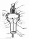
FIG. 1 is a cross-sectional view of a pressure indicator in accordance with one embodiment of the invention;
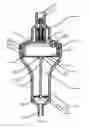
FIG. 2 is a sectional view of an upper cover of a pressure indicator in accordance with one embodiment of the invention;
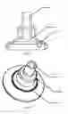
FIG. 3 is a top view of an upper cover of a pressure indicator in accordance with one embodiment of the invention;
FIG. 4 is a bottom view of an upper cover of a pressure indicator in accordance with one embodiment of the invention;
FIG. 5 is a schematic diagram of an intermediate member of a pressure indicator in accordance with one embodiment of the invention;
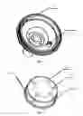
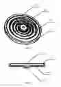
FIG. 6 is a schematic diagram of an elastic pressure-sensing diaphragm of a pressure indicator in accordance with one embodiment of the invention; and
FIG. 7 is a cross-sectional view of an elastic pressure-sensing diaphragm of a pressure indicator in accordance with one embodiment of the invention.
In the figures, the following reference numbers are used: 1. Upper cover; 1-1. Upper opening; 1-2. Check valve; 1-3. Lower space; 1-4. Gap; 1-5. Air channel; 1-6. Circular groove; 1-7. Positioning bulge; 2.Intermediate member; 2-1. Bonding gap; 2-2. Lower port; 2-3. Positioning groove; 2-4. Airway; 2-5. Air channel; 3. Elastic pressure-sensing diaphragm; 3-1. Circumferential flange; 3-2. Upper surface; 3-3. Lower surface; 3-4. Circumferential reinforcing bar; 3-5. Longitudinal reinforcing bar; 3-6. Groove; 4. Transmission indication rod; 4-1. Support end; 4-2. Connection rod; 4-3. Hole; 4-4. Indication end; 5. Lower cover; 5-1. Upper space; 5-2. Lower space; 5-3. Lower mouth.
DETAILED DESCRIPTION OF THE EMBODIMENTS
For further illustrating the invention, experiments detailing a pressure indicator are described below. It should be noted that the following examples are intended to describe and not to limit the invention.
As shown in FIG. 1, a pressure indicator comprises: an upper cover 1, an intermediate member 2, an elastic pressure-sensing 3, a transmission indication rod 4, and a lower cover 5. As shown in FIGS. 2-4, a check valve 1-2 is disposed in the upper cover 1, and the inner wall of the upper cover and the check valve 1-2 are assembled to form the upper opening 1-1. A circular groove 1-6 is disposed on the shoulder of the upper cover. The opening of the air channel 1-5 which communicates with the air is disposed inside the circular groove 1-6. The positioning bulge 1-7 of the upper cover 1 is connected to the positioning groove 2-3 of the intermediate member 2.
The lower port 2-2 of the intermediate member 2 is bonded with the circumferential flange 3-1 of the elastic pressure-sensing diaphragm 3. A groove 3-6 which coordinates with the support end 4-1 of the transmission indication rod 4 is disposed on the lower surface 3-3 of the elastic pressure-sensing diaphragm 3, as shown in FIG. 1.
The transmission indication rod 4 comprises: support end 4-1, connection rods 4-2 respectively connected to the top and bottom of the support end 4-1, indication end 4-4 and holes 4-3 on two sides, as shown in FIG. 1.
As shown in FIG. 1, the air channel 1-5 is formed by and runs through the upper cover 1 and the intermediate member 2.
As shown in FIGS. 6-7, at least one surface of the elastic pressure-sensing diaphragm 3 is provided with at least one circular or oval circumferential reinforcing bar 3-4 and at least one longitudinal reinforcing bar 3-5 which diffuses from center to all round. The longitudinal reinforcing bar 3-5 is between 2 and 16 in number, which is 4 in this example. The longitudinal reinforcing bar 3-5 and the circumferential reinforcing bar 3-4 are equally distributed in a vertically crossing way. The cross section of the circumferential reinforcing bar 3-4 and the longitudinal reinforcing bar 3-5 is designed to be waved, rectangular, triangular or other geometrical shapes. In this example, the cross section of the circumferential reinforcing bar 3-4 and the longitudinal reinforcing bar 3-5 is waved.
The elastic pressure sensing diaphragm 3 is a circular chip, oval chip or chip with other geometrical shapes, with a thickness of between 0.1 mm and 2.0 mm The elastic pressure sensing diaphragm 3 applied in this example is a circular chip, with a thickness of 0.5 mm.
The elastic pressure-sensing diaphragm 3 is made of rubber, silastic, thermoplastic elastomer (TPE) or other high elastic macromolecule material. In the example, rubber is employed.
An application method of the pressure indicator is summarized as follows.
Pressure measurement of a gas bag is taken as an example. As shown in FIG. 1, while the pressure indicator is in use, the lower mouth 5-3 is in airtight connection with the gas bag via an inflating tube. A syringe needle is applied to inflate the pressure indicator via the upper opening 1-1, and the gas enters the lower space 1-3 via the check valve 1-2, as shown in FIG. 2. Then, the gas passes through the gap 1-4 in FIG. 1 and enters the upper space 5-1 of the lower cover 5. On the one hand, as shown in FIG. 1, the gas passes through the holes 4-3 beneath the transmission indication rod 4, enters the lower space 5-2, and inflates the gas bag via the lower mouth 5-3. On the other hand, as shown in FIG. 1, the gas pushes the lower surface 3-3 of the elastic pressure-sensing diaphragm 3 to move upward, and pushes upward the transmission indication rod 4 in the same time, so that the change of the indication end 4-4 indicates the pressure change and that the number is accessible on the calibration line outside the lower cover. The upper surface of the elastic pressure-sensing diaphragm 3 communicates with the air via the air channel 1-5. The elastic pressure-sensing diaphragm 3 always indicates the pressure difference between the gas bag and atmosphere, and the structure of the pressure indicator guarantees the accuracy of the measurement.
While particular embodiments of the invention have been shown and described, it will be obvious to those skilled in the art that changes and modifications may be made without departing from the invention in its broader aspects, and therefore, the aim in the appended claims is to cover all such changes and modifications as fall within the true spirit and scope of the invention.
Claims
1. A pressure indicator, comprising:
a) a check valve;
b) an upper cover, the upper cover comprising an inner wall, a circular groove, and a positioning bulge;
c) an intermediate member, the intermediate member comprising a positioning groove, a lower port;
d) an elastic pressure-sensing diaphragm, the elastic pressure-sensing diaphragm comprising a circumferential flange, a lower surface;
e) a transmission indication rod, the transmission indication rod comprising a support end, a connection rod, and an indication end; and
f) a lower cover;
wherein
the check valve is disposed in the upper cover, and the inner wall of the upper cover and the check valve are assembled to form an upper opening; the circular groove is disposed on a shoulder of the upper cover; an opening of an air channel which communicates with the air is disposed inside the circular groove;
the positioning bulge of the upper cover is connected to the positioning groove of the intermediate member;
the lower port of the intermediate member is bonded with the circumferential flange of the elastic pressure-sensing diaphragm; the lower surface of the elastic pressure-sensing diaphragm is provided with a groove configured to coordinate with the support end of the transmission indication rod;
the connection rod is connected to a top and bottom of the support end, and the indication end comprises holes on two sides thereof.
2. The pressure indicator of claim 1, wherein the air channel is formed by and runs through the upper cover and the intermediate member.
3. The pressure indicator of claim 1, wherein at least one surface of the elastic pressure-sensing diaphragm is provided with at least one circular or oval circumferential reinforcing bar and at least one longitudinal reinforcing bar which diffuses from center to all round; the longitudinal reinforcing bar is between 2 and 16 in number; the longitudinal reinforcing bar and the circumferential reinforcing bar are uniformly distributed in a vertically crossing way; and a cross section of the circumferential reinforcing bar and the longitudinal reinforcing bar is designed to be waved, rectangular, triangular or other geometrical shapes.
4. The pressure indicator of claim 1, wherein the elastic pressure-sensing diaphragm is a circular chip, oval chip or chip with other geometrical shapes, with a thickness thereof of between 0.1 mm and 2.0 mm.
5. The pressure indicator of claim 1, wherein the elastic pressure-sensing diaphragm is made of rubber, silastic, thermoplastic elastomer (TPE) or other high elastic macromolecule material.
Images & Drawings included:
Sources:
- United States Patent and Trademark Office - verify current appl. status at the USPTO↗
Similar patent applications:
- » 20190107455
Pressure indicator that retains a high pressure indication - » 12652370
Fuel tank pressure indicator, including cap and container interface pressure indicator - » 20240261154
MANUALLY-OPERATED NEGATIVE PRESSURE WOUND THERAPY (NPWT) BANDAGE WITH IMPROVED PUMP EFFICIENCY, AUTOMATIC PRESSURE INDICATOR AND AUTOMATIC PRESSURE LIMITER - » 20050263155
Pressure indicator for positive pressure protection masks - » 20160076957
Pressure indicator with pressure-relief function - » 10687066
Tire pressure indicator providing a visual indication of tire pressure - » 20210169699
Manually-operated negative pressure wound therapy (NPWT) bandage with improved pump efficiency, automatic pressure indicator and automatic pressure limiter - » 20090254066
Reduced pressure indicator for a reduced pressure source - » 20130012894
Reduced pressure indicator for a reduced pressure source - » 20150224269
Pressure indicator for an oscillating positive expiratory pressure device
Recent applications in this class:
- » 20250288761 2025-09-18
Device for Helping User to Fix Oxygen Hose - » 20250281706 2025-09-11
SILENCER FOR CPAP DEVICE AND CPAP DEVICE - » 20250276140 2025-09-04
NON-INVASIVE ESTIMATION OF HEMODYNAMIC PARAMETERS DURING MECHANICAL VENTILATION - » 20250269125 2025-08-28
FLOW SENSORS AND METHODS OF USING THE SAME - » 20250256046 2025-08-14
MEDICAL DEVICE - » 20250213807 2025-07-03
METHODS, SYSTEMS AND APPARATUS FOR PACED BREATHING - » 20250205439 2025-06-26
SUPPORT FOR A BREATHING ASSISTANCE APPARATUS AND/OR ACCESSORIES - » 20250195802 2025-06-19
Adjustable Respiratory System of Concentration - Modulable Hydrogen and Oxygen Ventilator - » 20250161604 2025-05-22
LUNG FUNCTION MONITORING SYSTEM - » 20250108181 2025-04-03
PATIENT ATTACHMENT DETECTION IN RESPIRATORY FLOW THERAPY SYSTEMS