Multi-camera mobile teleconferencing platform
US20160046024A1
2016-02-18
14/924,453
2015-10-27
✅ Patent granted
US 10,259,119 B2
2019-04-16
-
-
Jonathan L Sample
2035-10-27
Abstract:
A remote controlled robot system that includes a mobile robot and a remote control station. A user can control movement of the robot from the remote control station. The mobile robot includes a camera system that can capture and transmit to the remote station a zoom image and a non-zoom image. The remote control station includes a monitor that displays a robot view field. The robot view field can display the non-zoom image. The zoom image can be displayed in the robot view field by highlighting an area of the non-zoom field. The remote control station may also store camera locations that allow a user to move the camera system to preset locations.
Inventors:
- Yulun Wang 188 🇺🇸 Goleta, CA, United States
- Keith Phillip Laby 34 🇺🇸 Oakland, CA, United States
- Jonathan Southard 60 🇺🇸 Santa Barbara, CA, United States
- Marco Pinter 121 🇺🇸 Santa Barbara, CA, United States
- John Cody Herzog 16 🇺🇸 Santa Barbara, CA, United States
- Charles S. Jordan 150 🇺🇸 Santa Barbara, CA, United States
Assignee:
- InTouch Technologies, Inc. 106 🇺🇸 Goleta, CA, United States
- INTOUCHT TECHNOLOGIES, INC. 1 🇺🇸 Goleta, CA, United States
Applicant:
Interested in similar patents?
Get notified when new applications in this technology area are published.
Classification:
B25J9/1689 » CPC main
Programme-controlled manipulators; Programme controls characterised by the tasks executed Teleoperation
B25J13/006 » CPC further
Controls for manipulators by means of a wireless system for controlling one or several manipulators
B25J19/02 IPC
Accessories fitted to manipulators, e.g. for monitoring, for viewing; Safety devices combined with or specially adapted for use in connection with manipulators Sensing devices
B25J19/021 » CPC further
Accessories fitted to manipulators, e.g. for monitoring, for viewing; Safety devices combined with or specially adapted for use in connection with manipulators; Sensing devices Optical sensing devices
B25J9/16 IPC
Programme-controlled manipulators Programme controls
B25J5/00 » CPC further
Manipulators mounted on wheels or on carriages
B25J13/06 » CPC further
Controls for manipulators Control stands, e.g. consoles, switchboards
A61B34/70 » CPC further
Computer-aided surgery; Manipulators or robots specially adapted for use in surgery Manipulators specially adapted for use in surgery
H04N7/185 » CPC further
Television systems; Closed circuit television systems, i.e. systems in which the signal is not broadcast for receiving images from a single remote source from a mobile camera, e.g. for remote control
A61B90/361 » CPC further
Instruments, implements or accessories specially adapted for surgery or diagnosis and not covered by any of the groups - , e.g. for luxation treatment or for protecting wound edges; Image-producing devices or illumination devices not otherwise provided for Image-producing devices, e.g. surgical cameras
G16H50/50 » CPC further
ICT specially adapted for medical diagnosis, medical simulation or medical data mining; ICT specially adapted for detecting, monitoring or modelling epidemics or pandemics for simulation or modelling of medical disorders
A61B90/00 IPC
Instruments, implements or accessories specially adapted for surgery or diagnosis and not covered by any of the groups - , e.g. for luxation treatment or for protecting wound edges
A61B34/25 » CPC further
Computer-aided surgery; Manipulators or robots specially adapted for use in surgery User interfaces for surgical systems
A61B34/00 IPC
Computer-aided surgery; Manipulators or robots specially adapted for use in surgery
H04N7/18 IPC
Television systems Closed circuit television systems, i.e. systems in which the signal is not broadcast
A61B34/30 » CPC further
Computer-aided surgery; Manipulators or robots specially adapted for use in surgery Surgical robots
B25J13/00 IPC
Controls for manipulators
A61B34/35 » CPC further
Computer-aided surgery; Manipulators or robots specially adapted for use in surgery; Surgical robots for telesurgery
Description
BACKGROUND OF THE INVENTION
1. Field of the Invention
The subject matter disclosed generally relates to the field of mobile two-way teleconferencing.
2. Background Information
Robots have been used in a variety of applications ranging from remote control of hazardous material to assisting in the performance of surgery. For example, U.S. Pat. No. 5,762,458 issued to Wang et al. discloses a system that allows a surgeon to perform minimally invasive medical procedures through the use of robotically controlled instruments. One of the robotic arms in the Wang system moves an endoscope that has a camera. The camera allows a surgeon to view a surgical area of a patient.
Tele-robots such as hazardous waste handlers and bomb detectors may contain a camera that allows the operator to view the remote site. Canadian Pat. No. 2289697 issued to Treviranus, et al. discloses a teleconferencing platform that has both a camera and a monitor. The platform includes mechanisms to both pivot and raise the camera and the monitor. The Treviranus patent also discloses embodiments with a mobile platform, and different mechanisms to move the camera and the monitor.
There has been marketed a mobile robot introduced by InTouch Technologies, Inc., the assignee of this application, under the trademarks COMPANION and RP-6. The InTouch robot is controlled by a user at a remote station. The remote station may be a personal computer with a joystick that allows the user to remotely control the movement of the robot. Both the robot and remote station have cameras, monitors, speakers and microphones to allow for two-way video/audio communication. The robot camera provides video images to a screen at the remote station so that the user can view the robot's surroundings and move the robot accordingly.
When moving the robot it is desirable to have a relatively wide view angle so that the user is provided with an optimal view of the robot's surroundings. It is also desirable to provide the robot with a zoom lens function so that the user can obtain a closer view of an image. It would be desirable to provide an interface for a remote controlled robot system that allows a user to easily switch between zoom and non-zoom images. It would also be desirable to provide memory functions so that the user can return to certain camera positions.
BRIEF SUMMARY OF THE INVENTION
A remote controlled robot system that includes a mobile robot and a remote control station. The mobile robot moves in response to robot control commands transmitted by the remote control station. The remote control station includes a monitor that displays a robot view field. The remote control station has a graphical user function that allows the robot view field to display either a zoom image or a non-zoom image provided by the mobile robot.
BRIEF DESCRIPTION OF THE DRAWINGS
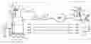
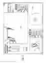
FIG. 1 is an illustration of a robotic system;
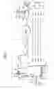
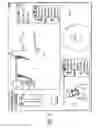
FIG. 2 is a schematic of an electrical system of a robot;
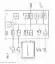
FIG. 3 is a further schematic of the electrical system of the robot;
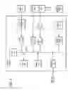
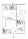
FIG. 4 is a graphical user interface of a remote station;
FIG. 5 is similar to FIG. 4 showing a portion of a non-zoom image highlighted;
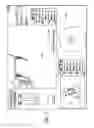
FIG. 6 is similar to FIG. 4 showing a zoom image being displayed by a robot view field;
FIG. 7 is similar to FIG. 4 showing a message that indicates a camera position has been stored.
DETAILED DESCRIPTION
Disclosed is a remote controlled robot system that includes a mobile robot and a remote control station. A user can control movement of the robot from the remote control station. The mobile robot includes a camera system that can capture and transmit to the remote station a zoom image and a non-zoom image. The remote control station includes a monitor that displays a robot view field. The robot view field can display the non-zoom image. The zoom image can be displayed in the robot view field by highlighting an area of the non-zoom field. The remote control station may also store camera positions that allow a user to move the camera system to preset positions.
Referring to the drawings more particularly by reference numbers, FIG. 1 shows a robotic system 10 that can be used to conduct a remote visit. The robotic system 10 includes a robot 12, a base station 14 and a remote control station 16. The remote control station 16 may be coupled to the base station 14 through a network 18. By way of example, the network 18 may be either a packet switched network such as the Internet, or a circuit switched network such has a Public Switched Telephone Network (PSTN) or other broadband system. The base station 14 may be coupled to the network 18 by a modem 20 or other broadband network interface device. By way of example, the base station 14 may be a wireless router. Alternatively, the robot 12 may have a direct connection to the network thru for example a satellite.
The remote control station 16 may include a computer 22 that has a monitor 24, a camera 26, a microphone 28 and a speaker 30. The computer 22 may also contain an input device 32 such as a joystick and/or a mouse and a keyboard 33. The control station 16 is typically located in a place that is remote from the robot 12. Although only one remote control station 16 is shown, the system 10 may include a plurality of remote stations. In general any number of robots 12 may be controlled by any number of remote stations 16 or other robots 12. For example, one remote station 16 may be coupled to a plurality of robots 12, or one robot 12 may be coupled to a plurality of remote stations 16, or a plurality of robots 12.
Each robot 12 includes a movement platform 34 that is attached to a robot housing 36. Also attached to the robot housing 36 is a pair of cameras 38 and 39, a monitor 40, a microphone(s) 42 and a speaker(s) 44. The microphone 42 and speaker 30 may create a stereophonic sound. The robot 12 may also have an antenna 46 that is wirelessly coupled to an antenna 48 of the base station 14. The system 10 allows a user at the remote control station 16 to move the robot 12 through operation of the input device 32. The robot cameras 38 and 39 are coupled to the remote monitor 24 so that a user at the remote station 16 can view a patient. Likewise, the robot monitor 40 is coupled to, the remote camera 26 so that the patient can view the user. The microphones 28 and 42, and speakers 30 and 44, allow for audible communication between the patient and the user.
Camera 38 may provide a wide angle view. Conversely, camera 39 may contain a zoom lens to provide a narrow angle view. Camera 39 can capture a zoom image that is transmitted to the remote control station. Camera 38 can capture a non-zoom image that can be transmitted to the remote control station. Although two cameras are shown and described, it is to be understood that the robot may contain only one camera that has the capability to provide a zoom image and a non-zoom image.
The remote station computer 22 may operate Microsoft OS software and WINDOWS XP or other operating systems such as LINUX. The remote computer 22 may also operate a video driver, a camera driver, an audio driver and a joystick driver. The video images may be transmitted and received with compression software such as MPEG CODEC.
FIGS. 2 and 3 show an embodiment of a robot 12. Each robot 12 may include a high level control system 50 and a low level control system 52. The high level control system 50 may include a processor 54 that is connected to a bus 56. The bus 56 is coupled to the cameras 38 and 39 by an input/output (I/O) ports 58 and 59, respectively. The monitor 40 is coupled to the bus 56 by a serial output port 60 and a VGA driver 62. The monitor 40 may include a touchscreen function that allows the patient to enter input by touching the monitor screen.
The speaker 44 is coupled to the bus 56 by a digital to analog converter 64. The microphone 42 is coupled to the bus 56 by an analog to digital converter 66. The high level controller 50 may also contain random access memory (RAM) device 68, a non-volatile RAM device 70 and a mass storage device 72 that are all coupled to the bus 62. The mass storage device 72 may contain medical files of the patient that can be accessed by the user at the remote control station 16. For example, the mass storage device 72 may contain a picture of the patient. The user, particularly a health care provider, can recall the old picture and make a side by side comparison on the monitor 24 with a present video image of the patient provided by the camera 38. The robot antennae 45 may be coupled to a wireless transceiver 74. By way of example, the transceiver 74 may transmit and receive information in accordance with IEEE 802.11b.
The controller 54 may operate with a LINUX OS operating system. The controller 54 may also operate MS WINDOWS along with video, camera and audio drivers for communication with the remote control station 16. Video information may be transceived using MPEG CODEC compression techniques. The software may allow the user to send e-mail to the patient and vice versa, or allow the patient to access the Internet. In general the high level controller 50 operates to control communication between the robot 12 and the remote control station 16.
The remote control station 16 may include a computer that is similar to the high level controller 50. The computer would have a processor, memory, I/O, software, firmware, etc. for generating, transmitting, receiving and processing information.
The high level controller 50 may be linked to the low level controller 52 by serial ports 76 and 78. The low level controller 52 includes a processor 80 that is coupled to a RAM device 82 and non-volatile RAM device 84 by a bus 86. Each robot 12 contains a plurality of motors 88 and motor encoders 90. The motors 88 can actuate the movement platform and move other parts of the robot such as the monitor and camera. The encoders 90 provide feedback information regarding the output of the motors 88. The motors 88 can be coupled to the bus 86 by a digital to analog converter 92 and a driver amplifier 94. The encoders 90 can be coupled to the bus 86 by a decoder 96. Each robot 12 also has a number of proximity sensors 98 (see also FIG. 1). The position sensors 98 can be coupled to the bus 86 by a signal conditioning circuit 100 and an analog to digital converter 102.
The low level controller 52 runs software routines that mechanically actuate the robot 12. For example, the low level controller 52 provides instructions to actuate the movement platform to move the robot 12. The low level controller 52 may receive movement instructions from the high level controller 50. The movement instructions may be received as movement commands from the remote control station or another robot. Although two controllers are shown, it is to be understood that each robot 12 may have one controller, or more than two controllers, controlling the high and low level functions.
The various electrical devices of each robot 12 may be powered by a battery(ies) 104. The battery 104 may be recharged by a battery recharger station 106 (see also FIG. 1). The low level controller 52 may include a battery control circuit 108 that senses the power level of the battery 104. The low level controller 52 can sense when the power falls below a threshold and then send a message to the high level controller 50.
The system may be the same or similar to a robotic system provided by the assignee InTouch-Health, Inc. of Santa Barbara, Calif. under the name RP-6. The system may also be the same or similar to the system disclosed in application Ser. No. 10/206,457 published on Jan. 29, 2004, which is hereby incorporated by reference.
FIG. 4 shows a display user interface (“DUI”) 120 that can be displayed at the remote station 16. The DUI 120 may include a robot view field 122 that displays a video image provided by the camera of the robot. The DUI 120 may also include a station view field 124 that displays a video image provided by the camera of the remote station 16. The DUI 120 may be part of an application program stored and operated by the computer 22 of the remote station 16.
The robot view field 122 may display a non-zoom image provided by the camera system of the robot. As shown by FIGS. 5 and 6, the user can highlight a portion of the non-zoom image to display a zoom image that corresponds to the highlighted area 126. By way of example, the highlighted area 126 can be initiated by left-clicking a mouse. The user can then drag the cursor 128, while holding down the left-click, to create the highlighted area 126. When the user releases the left-click, the remote station transmits commands to move the robot camera to point at the center of the highlighted area 126 and provide the zoom image corresponding to the area. Alternatively, the user can click on the mouse and a zoom area centered about the cursor will be displayed. The user can switch back to the non-zoom image by manipulating graphical icon 128 to move the slide bar to a far left position. This feature allows a user to readily switch between zoom and non-zoom images provided by the robot camera system. Thus a user can utilize the non-zoom image while moving the robot, and the zoom image feature to take a closer look at people or objects in the field of view.
The remote control station can store camera positions so that the user can readily go to a desired camera position. By way of example, a camera location can be stored by depressing a key on the keyboard. The F4 key may be depressed to store a camera position. As shown in FIG. 7 a visual indication 130 may be displayed to indicate to the user that the camera position has been stored. Subsequently pressing the key will cause the remote station to transmit a command(s) to move the robot camera system to the desired position. Other keys such as F5 through F12 can be used to create 9 potential stored camera locations. A new camera position can be stored by pressing and holding down one of the keys F4-F12.
The mouse 32 can be used to move the cameras of the robot. Movement of the mouse 32 may cause a corresponding movement of the cameras. The scale between the mouse and the camera movements may be varied by the user. Movement of the mouse may also cause the system to display zoom and non-zoom images.
In operation, the robot 12 may be placed in a home or a facility where one or more patients are to be monitored and/or assisted. The facility may be a hospital or a residential care facility. By way of example, the robot 12 may be placed in a home where a health care provider may monitor and/or assist the patient. Likewise, a friend or family member may communicate with the patient. The cameras and monitors at both the robot and remote control stations allow for teleconferencing between the patient and the person at the remote station(s).
The robot 12 can be maneuvered through the home or a facility by manipulating the input device 32 at a remote station 16. The robot 10 may be controlled by a number of different users. To accommodate for this the robot may have an arbitration system. The arbitration system may be integrated into the operating system of the robot 12. For example, the arbitration technique may be embedded into the operating system of the high-level controller 50.
By way of example, the users may be divided into classes that include the robot itself, a local user, a caregiver, a doctor, a family member, or a service provider. The robot 12 may override input commands that conflict with robot operation. For example, if the robot runs into a wall, the system may ignore all additional commands to continue in the direction of the wall. A local user is a person who is physically present with the robot. The robot could have an input device that allows local operation. For example, the robot may incorporate a voice recognition system that receives and interprets audible commands.
A caregiver is someone who remotely monitors the patient. A doctor is a medical professional who can remotely control the robot and also access medical files contained in the robot memory. The family and service users remotely access the robot. The service user may service the system such as by upgrading software, or setting operational parameters.
The robot 12 may operate in one of two different modes; an exclusive mode, or a sharing mode. In the exclusive mode only one user has access control of the robot. The exclusive mode may have a priority assigned to each type of user. By way of example, the priority may be in order of local, doctor, caregiver, family and then service user. In the sharing mode two or more users may share access with the robot. For example, a caregiver may have access to the robot, the caregiver may then enter the sharing mode to allow a doctor to also access the robot. Both the caregiver and the doctor can conduct a simultaneous tele-conference with the patient.
The arbitration scheme may have one of four mechanisms; notification, timeouts, queue and call back. The notification mechanism may inform either a present user or a requesting user that another user has, or wants, access to the robot. The timeout mechanism gives certain types of users a prescribed amount of time to finish access to the robot. The queue mechanism is an orderly waiting list for access to the robot. The call back mechanism informs a user that the robot can be accessed. By way of example, a family user may receive an e-mail message that the robot is free for usage. Tables I and II, show how the mechanisms resolve access request from the various users.
| TABLE I | |||||
| Access | Medical | Command | Software/Debug | Set | |
| User | Control | Record | Override | Access | Priority |
| Robot | No | No | Yes (1) | No | No |
| Local | No | No | Yes (2) | No | No |
| Caregiver | Yes | Yes | Yes (3) | No | No |
| Doctor | No | Yes | No | No | No |
| Family | No | No | No | No | No |
| Service | Yes | No | Yes | Yes | Yes |
| TABLE II | |
| Requesting User |
| Local | Caregiver | Doctor | Family | Service | |
| Current | Local | Not Allowed | Warn current user of | Warn current user of | Warn current user of | Warn current user of |
| User | pending user | pending user | pending user | pending user | ||
| Notify requesting | Notify requesting user | Notify requesting user | Notify requesting | |||
| user that system is in | that system is in use | that system is in use | user that system is in | |||
| use | Set timeout = 5 m | Set timeout = 5 m | use | |||
| Set timeout | Call back | No timeout | ||||
| Call back | ||||||
| Caregiver | Warn current user | Not Allowed | Warn current user of | Warn current user of | Warn current user of | |
| of pending user. | pending user | pending user | pending user | |||
| Notify requesting | Notify requesting user | Notify requesting user | Notify requesting | |||
| user that system is | that system is in use | that system is in use | user that system is in | |||
| in use. | Set timeout = 5 m | Set timeout = 5 m | use | |||
| Release control | Queue or callback | No timeout | ||||
| Callback | ||||||
| Doctor | Warn current user | Warn current user of | Warn current user of | Notify requesting user | Warn current user of | |
| of pending user | pending user | pending user | that system is in use | pending user | ||
| Notify requesting | Notify requesting | Notify requesting user | No timeout | Notify requesting | ||
| user that system is | user that system is in | that system is in use | Queue or callback | user that system is in | ||
| in use | use | No timeout | use | |||
| Release control | Set timeout = 5 m | Callback | No timeout | |||
| Callback | ||||||
| Family | Warn current user | Notify requesting | Warn current user of | Warn current user of | Warn current user of | |
| of pending user | user that system is in | pending user | pending user | pending user | ||
| Notify requesting | use | Notify requesting user | Notify requesting user | Notify requesting | ||
| user that system is | No timeout | that system is in use | that system is in use | user that system is in | ||
| in use | Put in queue or | Set timeout = 1 m | Set timeout = 5 m | use | ||
| Release Control | callback | Queue or callback | No timeout | |||
| Callback | ||||||
| Service | Warn current user | Notify requesting | Warn current user of | Warn current user of | Not Allowed | |
| of pending user | user that system is in | request | pending user | |||
| Notify requesting | use | Notify requesting user | Notify requesting user | |||
| user that system is | No timeout | that system is in use | that system is in use | |||
| in use | Callback | No timeout | No timeout | |||
| No timeout | Callback | Queue or callback | ||||
The information transmitted between the station 16 and the robot 12 may be encrypted. Additionally, the user may have to enter a password to enter the system 10. A selected robot is then given an electronic key by the station 16. The robot 12 validates the key and returns another key to the station 16. The keys are used to encrypt information transmitted in the session.
The robot 12 and remote station 16 transmit commands through the broadband network 18. The commands can be generated by the user in a variety of ways. For example, commands to move the robot may be generated by moving the joystick 32 (see FIG. 1). The commands are preferably assembled into packets in accordance with TCP/IP protocol. Table III provides a list of control commands that are generated at the remote station and transmitted to the robot through the network.
| TABLE III |
| Control Commands |
| Command | Example | Description |
| drive | drive 10.0 0.0 5.0 | The drive command directs the robot to move |
| at the specified velocity (in cm/sec) in the | ||
| (x, y) plane, and turn its facing at the | ||
| specified rate (degrees/sec). | ||
| goodbye | goodbye | The goodbye command terminates a user |
| session and relinquishes control of the | ||
| robot | ||
| gotoHomePosition | gotoHomePosition 1 | The gotoHomePosition command moves the head |
| to a fixed “home” position (pan and tilt), | ||
| and restores zoom to default value. The | ||
| index value can be 0, 1, or 2. The exact | ||
| pan/tilt values for each index are specified | ||
| in robot configuration files. | ||
| head | head vel pan 5.0 tilt | The head command controls the head motion. |
| 10.0 | It can send commands in two modes, | |
| identified by keyword: either positional | ||
| (“pos”) or velocity (“vol”). In velocity | ||
| mode, the pan and tilt values are desired | ||
| velocities of the head on the pan and tilt | ||
| axes, in degree/sec. A single command can | ||
| include just the pan section, or just the | ||
| tilt section, or both. | ||
| keepalive | keepalive | The keepalive command causes no action, but |
| keeps the communication (socket) link open | ||
| so that a session can continue. In scripts, | ||
| it can be used to introduce delay time into | ||
| the action. | ||
| odometry | odometry 5 | The odometry command enables the flow of |
| odometry messages from the robot. The | ||
| argument is the number of times odometry is | ||
| to be reported each second. A value of 0 | ||
| turns odometry off. | ||
| reboot | reboot | The reboot command causes the robot computer |
| to reboot immediately. The ongoing session | ||
| is immediately broken off. | ||
| restoreHeadPosition | restoreHeadPosition | The restoreHeadPosition functions like the |
| gotoHomePosition command, but it homes the | ||
| head to a position previously saved with | ||
| gotoHomePosition. | ||
| saveHeadPosition | saveHeadPosition | The saveHeadPosition command causes the |
| robot to save the current head position (pan | ||
| and tilt) in a scratch location in temporary | ||
| storage so that this position can be | ||
| restored. Subsequent calls to | ||
| “restoreHeadPosition” will restore this | ||
| saved position. Each call to | ||
| saveHeadPosition overwrites any previously | ||
| saved position. | ||
| setCameraFocus | setCameraFocus 100.0 | The setCameraFocus command controls focus |
| for the camera on the robot side. The value | ||
| sent is passed “raw” to the video | ||
| application running on the robot, which | ||
| interprets it according to its own | ||
| specification. | ||
| setCameraZoom | setCameraZoom 100.0 | The setCameraZoom command controls zoom for |
| the camera on the robot side. The value | ||
| sent is passed “raw” to the video | ||
| application running on the robot, which | ||
| interprets it according to its own | ||
| specification. | ||
| shutdown | Shutdown | The shutdown command shuts down the robot |
| and powers down its computer. | ||
| stop | stop | The stop command directs the robot to stop |
| moving immediately. It is assumed this will | ||
| be as sudden a stop as the mechanism can | ||
| safely accommodate. | ||
| timing | Timing 3245629 500 | The timing message is used to estimate |
| message latency. It holds the UCT value | ||
| (seconds + milliseconds) of the time the | ||
| message was sent, as recorded on the sending | ||
| machine. To do a valid test, you must | ||
| compare results in each direction (i.e., | ||
| sending from machine A to machine B, then | ||
| from machine B to machine A) in order to | ||
| account for differences in the clocks | ||
| between the two machines. The robot records | ||
| data internally to estimate average and | ||
| maximum latency over the course of a | ||
| session, which it prints to log files. | ||
| userTask | userTask “Jane Doe” | The userTask command notifies the robot of |
| “Remote Visit” | the current user and task. It typically is | |
| sent once at the start of the session, | ||
| although it can be sent during a session if | ||
| the user and/or task change. The robot uses | ||
| this information for record-keeping. | ||
Table IV provides a list of reporting commands that are generated by the robot and transmitted to the remote station through the network.
| TABLE IV |
| Reporting Commands |
| Command | Example | Description |
| abnormalExit | abnormalExit | This message informs the user that the robot |
| software has crashed or otherwise exited | ||
| abnormally. Te robot software catches top- | ||
| level exceptions and generates this message | ||
| if any such exceptions occur. | ||
| bodyType | bodyType 3 | The bodyType message informs the station |
| which type body (using the numbering of the | ||
| mechanical team) the current robot has. | ||
| This allows the robot to be drawn correctly | ||
| in the station user interface, and allows | ||
| for any other necessary body-specific | ||
| adjustments. | ||
| driveEnabled | driveEnabled true | This message is sent at the start of a |
| session to indicate whether the drive system | ||
| is operational. | ||
| emergencyShutdown | emergencyShutdown | This message informs the station that the |
| robot software has detected a possible | ||
| “runaway” condition (an failure causing the | ||
| robot to move out of control) and is | ||
| shutting the entire system down to prevent | ||
| hazardous motion. | ||
| odometry | odometry 10 20 340 | The odometry command reports the current |
| (x, y) position (cm) and body orientation | ||
| (degrees) of the robot, in the original | ||
| coordinate space of the robot at the start | ||
| of the session. | ||
| sensorGroup | group_data | Sensors on the robot are arranged into |
| groups, each group of a single type (bumps, | ||
| range sensors, charge meter, etc.) The | ||
| sensorGroup message is sent once per group | ||
| at the start of each session. It contains | ||
| the number, type, locations, and any other | ||
| relevant data for the sensors in that group. | ||
| The station assumes nothing about the | ||
| equipment carried on the robot; everything | ||
| it knows about the sensors comes from the | ||
| sensorGroup messages. | ||
| sensorState | groupName state data | The sensorState command reports the current |
| state values for a specified group of | ||
| sensor. The syntax and interpretation for | ||
| the state data is specific to each group. | ||
| This message is sent once for each group at | ||
| each sensor evaluation (normally several | ||
| times per second). | ||
| systemError | systemError | This message informs the station user of a |
| driveController | failure in one of the robot's subsystems. | |
| The error_type argument indicates which | ||
| subsystem failed, including driveController, | ||
| sensorController, headHome. | ||
| systemInfo | systemInfo wireless 45 | This message allows regular reporting of |
| information that falls outside the sensor | ||
| system such as wireless signal strength. | ||
| text | text “This is some | The text string sends a text string from the |
| text” | robot to the station, where the string is | |
| displayed to the user. This message is used | ||
| mainly for debugging. | ||
| version | version 1.6 | This message identifies the software version |
| currently running on the robot. It is sent | ||
| once at the start of the session to allow | ||
| the station to do any necessary backward | ||
| compatibility adjustments. | ||
The processor 54 of the robot high level controller 50 may operate a program that determines whether the robot 12 has received a robot control command within a time interval. For example, if the robot 12 does not receive a control command within 2 seconds then the processor 54 provides instructions to the low level controller 50 to stop the robot 12. Although a software embodiment is described, it is to be understood that the control command monitoring feature could be implemented with hardware, or a combination of hardware and software. The hardware may include a timer that is reset each time a control command is received and generates, or terminates, a command or signal, to stop the robot.
The remote station computer 22 may monitor the receipt of video images provided by the robot camera. The computer 22 may generate and transmit a STOP command to the robot if the remote station does not receive or transmit an updated video image within a time interval. The STOP command causes the robot to stop. By way of example, the computer 22 may generate a STOP command if the remote control station does not receive a new video image within 2 seconds. Although a software embodiment is described, it is to be understood that the video image monitoring feature could be implemented with hardware, or a combination of hardware and software. The hardware may include a timer that is reset each time a new video image is received and generates, or terminates, a command or signal, to generate the robot STOP command.
While certain exemplary embodiments have been described and shown in the accompanying drawings, it is to be understood that such embodiments are merely illustrative of and not restrictive on the broad invention, and that this invention not be limited to the specific constructions and arrangements shown and described, since various other modifications may occur to those ordinarily skilled in the art.
Claims
What is claimed is:1. A remote controlled robot system, comprising:
a mobile robot with a camera system that can capture a zoom image and a non-zoom image; and,
a remote control station that transmits commands to control said mobile robot, said remote control station includes a monitor that displays a robot view field and a graphical user interface function that switches said robot view field to display said zoom image or said non-zoom image.
2. The system of claim 1, wherein said graphical user interface function includes a highlighted area.
3. The system of claim 2, wherein said highlighted area is initiated by depressing a mouse.
4. The system of claim 1, wherein said camera system includes a first camera that provides said zoom image and a second camera that provides said non-zoom image.
5. The system of claim 2, wherein said camera system moves to a center of said highlighted area.
6. The system of claim 1, wherein said remote control station includes at least one stored camera position.
7. The system of claim 6, wherein said remote control station includes a keyboard and said stored camera position is stored by depressing a key on said keyboard.
8. The system of claim 7, wherein said mobile robot moves said camera system to said stored camera position in response to said key being depressed.
9. The system of claim 6, wherein said monitor displays an indication that said stored camera position has been stored.
10. A remote controlled robot system, comprising:
a mobile robot with a movable camera system; and,
a remote control station that transmits commands to control said mobile robot, said remote control station stores a camera position and transmits a command to said mobile robot to move said camera system to said stored camera position.
11. The system of claim 10, wherein said remote control station includes a keyboard and said stored camera position is stored by depressing a key on said keyboard.
12. The system of claim 11, wherein said robot moves said camera system to said stored camera position in response to said key being depressed.
13. The system of claim 10, wherein said monitor displays an indication that said stored camera position has been stored.
14. A remote controlled robot system, comprising:
a mobile robot with camera means for capturing a zoom image and a non-zoom image; and,
a remote control station that transmits commands to control said mobile robot, said remote control station includes a monitor that displays a robot view field and switching means for switching said robot view field to display said zoom image or said non-zoom image.
15. The system of claim 14, wherein said switching means includes a highlighted area.
16. The system of claim 15, wherein said highlighted area is initiated by depressing a mouse.
17. The system of claim 14, wherein said camera means includes a first camera that provides said zoom image and a second camera that provides said non-zoom image.
18. The system of claim 15, wherein said camera means moves to a center of said highlighted area.
19. The system of claim 14, wherein said remote control station includes at least one stored camera position.
20. The system of claim 19, wherein said remote control station includes a keyboard and said stored camera position is stored by depressing a key on said keyboard.
21. The system of claim 20, wherein said robot moves said camera system to said stored camera position in response to said key being depressed.
22. The system of claim 19, wherein said monitor displays an indication that said stored camera position has been stored.
23. A remote controlled robot system, comprising:
a mobile robot with a movable camera system; and,
a remote control station that transmits commands to control said mobile robot, said remote control station having storing means for storing a camera position, and transmits a command to said mobile robot to move said camera system to said stored camera position.
24. The system of claim 23, wherein said remote control station includes a keyboard and said stored camera position is stored by depressing a key on said keyboard.
25. The system of claim 24, wherein said robot moves said camera system to said stored camera position in response to said key being depressed.
26. The system of claim 23, wherein said monitor displays an indication that said stored camera position has been stored.
27. A method for remotely controlling a robot that has a camera, comprising:
transmitting a robot control command from a remote control station;
receiving the robot control command at a robot that has a camera;
moving the robot in accordance with the robot control command;
displaying on a monitor of the remote control station a non-zoom image in a robot view field; and,
switching the robot view field to display a zoom image.
28. The method of claim 27, wherein the zoom image corresponds to an area of the non-zoom image that is highlighted.
29. The method of claim 27, further comprising storing a camera position.
30. A method for remotely controlling a robot that has a camera, comprising:
transmitting a robot control command from a remote control station;
receiving the robot control command at a robot that has a camera;
moving the robot in accordance with the robot control command;
storing a camera position in the remote control station;
transmitting the camera position to the robot; and,
moving the camera to the stored camera position.
31. The method of claim 30, wherein the camera position is stored by depressing a key of a keyboard.
Images & Drawings included:
Sources:
- United States Patent and Trademark Office - verify current appl. status at the USPTO↗
Similar patent applications:
- » 20070078566
Multi-camera mobile teleconferencing platform
Recent applications in this class:
- » 20250282055 2025-09-11
RAIL ASSEMBLY FOR TABLE-MOUNTED MANIPULATOR SYSTEM, AND RELATED DEVICES, SYSTEMS AND METHODS - » 20250269535 2025-08-28
FORCE GUIDANCE TELEROBOTIC SYSTEM AND CONTROL METHOD BASED ON DUAL-ARM COLLABORATIVE POTENTIAL FIELD - » 20250249590 2025-08-07
SYSTEM AND METHOD FOR AUTOMATED OPERATION AND MAINTENANCE OF A ROBOT SYSTEM - » 20250249589 2025-08-07
SYSTEMS AND METHODS FOR TELEOPERATED ROBOT - » 20250249588 2025-08-07
REMOTE CONTROL SYSTEM, ROBOT REMOTE CONTROL METHOD, AND REMOTE CONTROL PROGRAM - » 20250242497 2025-07-31
Securable Robotic Controller - » 20250229427 2025-07-17
MASTER-SLAVE TELEOPERATION ROBOT SYSTEM BASED ON FORCE MIXED REALITY - » 20250214244 2025-07-03
ROBOT TELEOPERATION SYSTEM AND METHOD - » 20250187197 2025-06-12
REMOTE CONTROL OF ROBOTIC SYSTEMS AND UNITS - » 20250187196 2025-06-12
SYSTEM FOR CONTROLLING ROBOT AND METHOD THEREOF
Recent applications for this Assignee:
- » 20200273565 2020-08-27
Graphical user interfaces including touchpad driving interfaces for telemedicine devices - » 20200009736 2020-01-09
Social behavior rules for a medical telepresence robot - » 20190375102 2019-12-12
Interfacing with a mobile telepresence robot - » 20190328229 2019-10-31
Telehealth cart that supports a removable tablet with seamless audio/video switching - » 20190190965 2019-06-20
Systems and methods for dynamic bandwidth allocation - » 20190043621 2019-02-07
Modular telehealth cart with thermal imaging and touch screen user interface - » 20180243914 2018-08-30
Protocol for a remotely controlled videoconferencing robot - » 20180099412 2018-04-12
Social behavior rules for a medical telepresence robot - » 20180074552 2018-03-15
Server connectivity control for a tele-presence robot - » 20180071917 2018-03-15
Medical tele-robotic system with a master remote station with an arbitrator