Integrated depth camera
US20160050346A1
2016-02-18
14/458,298
2014-08-13
✅ Patent granted
US 9,420,149 B2
2016-08-16
-
-
John Villecco
2035-03-10
Abstract:
The depth camera includes a control module and a lighting module. The control module includes a control board, a control unit mounted on the control board, a seat mounted on the control board and over the control unit and a lens rooted in the seat. The lighting module is superposed on the control module and includes a lighting board with a through hole for receiving the lens, lighting units mounted on the lighting board and a reflector set composed of a base plate and reflectors formed thereon. Each reflector has an opening surrounding one of the lighting units.
Inventors:
- Ling-Wei LIU 8 🇹🇼 Taipei City, Taiwan
- Hung-Chang TSAI 7 🇹🇼 Taipei City, Taiwan
- Ling-Wei Liu 5 🇹🇼 Taipei, Taiwan
- Hung-Chang Tsai 4 🇹🇼 Taipei, Taiwan
Assignee:
- LIPS CORPORATION 2 🇹🇼 Taipei City, Taiwan
- LIPS CORPORATION 5 🇹🇼 Taipei, Taiwan
Applicant:
Interested in similar patents?
Get notified when new applications in this technology area are published.
Classification:
H04N5/2252 » CPC main
Details of television systems; Studio circuitry; Studio devices; Studio equipment ; Cameras comprising an electronic image sensor, e.g. digital cameras, video cameras, TV cameras, video cameras, camcorders, webcams, camera modules for embedding in other devices, e.g. mobile phones, computers or vehicles; Television cameras ; Cameras comprising an electronic image sensor, e.g. digital cameras, video cameras, camcorders, webcams, camera modules specially adapted for being embedded in other devices, e.g. mobile phones, computers or vehicles; Constructional details Housings
G06F3/017 » CPC further
Input arrangements for transferring data to be processed into a form capable of being handled by the computer; Output arrangements for transferring data from processing unit to output unit, e.g. interface arrangements; Input arrangements or combined input and output arrangements for interaction between user and computer Gesture based interaction, e.g. based on a set of recognized hand gestures
H04N5/225 IPC
Details of television systems; Studio circuitry; Studio devices; Studio equipment ; Cameras comprising an electronic image sensor, e.g. digital cameras, video cameras, TV cameras, video cameras, camcorders, webcams, camera modules for embedding in other devices, e.g. mobile phones, computers or vehicles Television cameras ; Cameras comprising an electronic image sensor, e.g. digital cameras, video cameras, camcorders, webcams, camera modules specially adapted for being embedded in other devices, e.g. mobile phones, computers or vehicles
G06F3/01 IPC
Input arrangements for transferring data to be processed into a form capable of being handled by the computer; Output arrangements for transferring data from processing unit to output unit, e.g. interface arrangements Input arrangements or combined input and output arrangements for interaction between user and computer
G06K9/00 IPC
Methods or arrangements for recognising patterns
Description
BACKGROUND OF THE INVENTION
1. Technical Field
The invention relates to cameras, particularly to depth cameras.
2. Related Art
A depth camera can be used to control a computer through a gesture. Moreover, a depth camera can be further used to control a TV game through a body motion. This makes human-machine interaction more intuitive.
Such human-machine interaction needs a depth camera which can store a three-dimensional image into a two-dimensional format. A depth camera can measure a Z-axis distance between every shot point and the camera so that it can record three-dimensional image data.
A common method for measuring the Z-axis distance is to use the principle of time of flight (TOF). Simply speaking, a time period from a light beam emitted by a light source to be reflected by a shot point to come back to the origin can be used to calculate the Z-axis distance.
Therefore, the light source is an essential element of the TOF principle. A conventional TOF depth camera is provided with multiple light sources. To ensure the light beams from the light sources are absolutely parallel, each light source is further provided with a reflector. However, the reflectors are separate parts which must be individually installed over the light sources. Such installation always makes the light beams deflective, and finally, the distance measurement will be inaccurate.
SUMMARY OF THE INVENTION
An object of the invention is to provide an integrated depth camera, which has a modularized light source set. This can simplify the installation process of the light source set and ensure the accuracy of installation.
To accomplish the above object, the depth camera of the invention includes a control module and a lighting module. The control module includes a control board, a control unit mounted on the control board, a seat mounted on the control board and over the control unit and a lens rooted in the seat. The lighting module is superposed on the control module and includes a lighting board with a through hole for receiving the lens, lighting units mounted on the lighting board and a reflector set composed of a base plate and reflectors formed thereon. Each reflector has an opening surrounding one of the lighting units.
BRIEF DESCRIPTION OF THE DRAWINGS
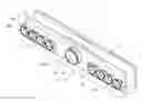
FIG. 1 is an exploded view of the invention;
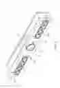
FIG. 2 is an assembled view of the invention;
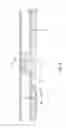
FIG. 3 is a sectional view of the invention; and
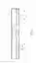
FIG. 4 is a schematic view of the invention.
DETAILED DESCRIPTION OF THE INVENTION
Please refer to FIGS. 1 and 2. The depth camera of the invention includes a control module 1 and a lighting module 2. The control module 1 and the lighting module 2 are installed in a case 3. As shown in FIG. 2, the control module 1 further includes a control board 11. A control unit 12 is mounted on the control board 11. In the shown embodiment, the control unit 12 is a control chip for controlling the operation of the depth camera. A seat 13 is mounted on the control board 11. The seat 13 is formed with a connecting hole 131 surrounding the control unit 12. An edge of the connecting hole 131 is formed with a thread 132. A lens 14 is rooted in the connecting hole 131 and electrically connected to the control unit 12. The lens 14 has a connecting end 141 with a thread for screwing with the connecting hole 131.
The lighting module 2 includes a lighting board 21 electrically connected to the control board 11. The lighting board 21 is formed with a through hole 211 for receiving the lens 14. In other words, the lens 14 passes through the lighting board 21 as shown in FIG. 3. The lighting board 21 is mounted by multiple lighting units 22 under control of the control unit 21. The lighting units 22 are arranged in a line and beside the through hole 211. The lighting units 22 may be an infrared or laser light source. The lighting board 21 is provided with at least one reflector set 23. In the shown embodiment, the reflector set 23 is two in number. Each reflector set 23 includes a base plate 231 and multiple reflectors 232 mounted thereon. The bottom of each reflector 232 is formed with an opening 233 surrounding one of the lighting units 232. The base plate 231 is provided with fixing rods 234 for being inserted into fixing holes 212 of the lighting board 21. The lighting units 22 are separately surrounded by the reflectors 232 in a one-to-one manner as shown in FIG. 3.
Please refer to FIG. 4. As shown, the lighting units 22 of the lighting module 2 are installed with the reflectors 232 in a module manner. The lighting units 22 emit light beams while the depth camera is working, and the reflectors 232 can keep the light beams concentrative to reach the shot object (as the arrows shown in the figure). The modularized reflectors 23 ensure the installing accuracy and simplify the installing process.
It will be appreciated by persons skilled in the art that the above embodiment has been described by way of example only and not in any limitative sense, and that various alterations and modifications are possible without departure from the scope of the invention as defined by the appended claims. It will be appreciated by persons skilled in the art that the above embodiment has been described by way of example only and not in any limitative sense, and that various alterations and modifications are possible without departure from the scope of the invention as defined by the appended claims.
Claims
What is claimed is:1. A depth camera comprising:
a control module comprising:
a control board;
a control unit, mounted on the control board;
a seat, mounted on the control board and over the control unit, and having a connecting hole surrounding the control unit; and
a lens, rooted in the connecting hole of the seat; and
a lighting module, superposed on and electrically connected to the control module, comprising:
a lighting board, having a through hole for receiving the lens, and electrically connected to the control unit;
lighting units, mounted on the lighting board; and
a reflector set, having a base plate and multiple reflectors formed thereon, and each reflector having an opening surrounding one of the lighting units.
2. The depth camera of claim 1, wherein the base plate is provided with fixing rods, multiple fixing holes are formed in the lighting board so that the fixing rods are separately inserted into the fixing holes.
3. The depth camera of claim 1, wherein the lighting units are infrared or laser light sources.
4. The depth camera of claim 1, wherein the lens has a connecting end with a thread.
5. The depth camera of claim 4, wherein an edge of the connecting hole is formed with a thread. for screwing with the connecting end.
6. The depth camera of claim 1, further comprising a case receiving the control module and the lighting module.
Images & Drawings included:

Sources:
- United States Patent and Trademark Office - verify current appl. status at the USPTO↗
Similar patent applications:
- » 20090231425
Controller with an integrated depth camera - » 20130208900
DEPTH CAMERA WITH INTEGRATED THREE-DIMENSIONAL AUDIO - » 20120106803
Apparatus and method for dynamically controlling integration time of depth camera for accuracy improvement - » 20120075534
Integrated low power depth camera and projection device - » 20210247632
Optical elements for integrated IR and visible camera for depth sensing and systems incorporating the same - » 20160344996
Integrated digital camera platform with NIR apodization filter for enhanced depth sensing and image processing - » 20160198147
Correction of depth images from T-O-F 3D camera with electronic-rolling-shutter for light modulation changes taking place during light integration
Recent applications in this class:
- » 20240129607 2024-04-18
Camera housing structure for enhanced manufacture assembly and repair - » 20240098348 2024-03-21
Camera module on flexible interconnect tape - » 20230403447 2023-12-14
SHARED WINDOW FOR COMPUTING DEVICE CAMERA LENSES AND PHOTOFLASH - » 20230269449 2023-08-24
Retractable camera module and electronic device - » 20230217089 2023-07-06
Protective lens cover for a camera - » 20230188815 2023-06-15
Camera with dock having automated alignment - » 20230168500 2023-06-01
SMART GLASSES AND CAMERA DEVICE THEREOF - » 20230156306 2023-05-18
Imaging apparatus - » 20230142061 2023-05-11
Camera device - » 20230132784 2023-05-04
Thermally stable sawmill scanner
Recent applications for this Assignee:
- » 20200074654 2020-03-05
Production apparatus with depth image detection - » 20160050347 2016-02-18
Depth camera - » 20160050347 2016-02-18
Depth camera - » 20150365654 2015-12-17
Method for correcting image phase - » 20150271472 2015-09-24
System and method for stereoscopic photography