Heat sink and mounting bracket arrangement
US20160131442A1
2016-05-12
14/590,675
2015-01-06
✅ Patent granted
US 9,587,891 B2
2017-03-07
-
-
Leonard R Leo
Pai Patent & Trademark Law Firm | Chao-Chang David Pai
2035-08-09
Abstract:
A heat sink and mounting bracket arrangement includes a radiation fin module including a stack of radiation fins and an insertion hole located in one end of the stack of radiation fins, and a mounting bracket made from a metal plate sheet by stamping and including a bottom panel clamped on a bottom wall of the stack of radiation fins, an angled mounting panel rearwardly extending from one end of the bottom panel, a mounting slot cut through opposing top and bottom walls of the mounting panel for the mounting of a fastening member to affix the mounting bracket to an external substrate, and an angled plug plate forwardly extending from the bottom panel and tightly press-fitted into the insertion hole of the radiation fin module.
Applicant:
Interested in similar patents?
Get notified when new applications in this technology area are published.
Classification:
F28D15/0233 » CPC further
Heat-exchange apparatus with the intermediate heat-transfer medium in closed tubes passing into or through the conduit walls ; Heat-exchange apparatus employing intermediate heat-transfer medium or bodies in which the medium condenses and evaporates, e.g. heat pipes the conduits having a particular shape, e.g. non-circular cross-section, annular
H01L23/4006 » CPC further
Details of semiconductor or other solid state devices; Arrangements for cooling, heating, ventilating or temperature compensation ; Temperature sensing arrangements; Mountings or securing means for detachable cooling or heating arrangements ; fixed by friction, plugs or springs with bolts or screws
F28D15/02 IPC
Heat-exchange apparatus with the intermediate heat-transfer medium in closed tubes passing into or through the conduit walls ; Heat-exchange apparatus employing intermediate heat-transfer medium or bodies in which the medium condenses and evaporates, e.g. heat pipes
H01L2924/0002 » CPC further
Indexing scheme for arrangements or methods for connecting or disconnecting semiconductor or solid-state bodies as covered by; Technical content checked by a classifier Not covered by any one of groups , and
F28F9/007 » CPC further
Casings; Header boxes; Auxiliary supports for elements; Auxiliary members within casings Auxiliary supports for elements
F28D15/0275 » CPC further
Heat-exchange apparatus with the intermediate heat-transfer medium in closed tubes passing into or through the conduit walls ; Heat-exchange apparatus employing intermediate heat-transfer medium or bodies in which the medium condenses and evaporates, e.g. heat pipes Arrangements for coupling heat-pipes together or with other structures, e.g. with base blocks; Heat pipe cores
H01L23/40 IPC
Details of semiconductor or other solid state devices; Arrangements for cooling, heating, ventilating or temperature compensation ; Temperature sensing arrangements Mountings or securing means for detachable cooling or heating arrangements ; fixed by friction, plugs or springs
H01L23/3672 » CPC further
Details of semiconductor or other solid state devices; Arrangements for cooling, heating, ventilating or temperature compensation ; Temperature sensing arrangements; Selection of materials, or shaping, to facilitate cooling or heating, e.g. heatsinks; Cooling facilitated by shape of device Foil-like cooling fins or heat sinks
H05K7/20 IPC
Constructional details common to different types of electric apparatus Modifications to facilitate cooling, ventilating, or heating
H05K7/20 IPC
Constructional details common to different types of electric apparatus Modifications to facilitate cooling, ventilating, or heating
F28F3/02 » CPC main
Plate-like or laminated elements; Assemblies of plate-like or laminated elements Elements or assemblies thereof with means for increasing heat-transfer area, e.g. with fins, with recesses, with corrugations
F28F1/32 » CPC further
Tubular elements; Assemblies of tubular elements; Tubular elements and assemblies thereof with means for increasing heat-transfer area, e.g. with fins, with projections, with recesses the means being only outside the tubular element and extending transversely the means having portions engaging further tubular elements
H01L23/367 IPC
Details of semiconductor or other solid state devices; Arrangements for cooling, heating, ventilating or temperature compensation ; Temperature sensing arrangements; Selection of materials, or shaping, to facilitate cooling or heating, e.g. heatsinks Cooling facilitated by shape of device
H01L23/427 » CPC further
Details of semiconductor or other solid state devices; Arrangements for cooling, heating, ventilating or temperature compensation ; Temperature sensing arrangements; Fillings or auxiliary members in containers or encapsulations selected or arranged to facilitate heating or cooling Cooling by change of state, e.g. use of heat pipes
H01L23/4093 » CPC further
Details of semiconductor or other solid state devices; Arrangements for cooling, heating, ventilating or temperature compensation ; Temperature sensing arrangements; Mountings or securing means for detachable cooling or heating arrangements ; fixed by friction, plugs or springs Snap-on arrangements, e.g. clips
Description
BACKGROUND OF THE INVENTION
(a) Field of the Invention
The present invention relates to heat sink technology, and more particularly to a heat sink and mounting bracket arrangement, which comprises a radiation fin module, and a mounting bracket press-fitted into the radiation fin module and clamped on the bottom wall of the radiation fin module for enabling the radiation fin module to be conveniently fastened to a substrate.
(b) Description of the Prior Art
Conventional heat sinks generally comprise a heat sink base and a radiation fin module. Some heat sinks have heat pipes added thereto, and a heat transfer plate bonded to the heat pipes outside the radiation fin module and the heat sink base. In this design, each heat pipe has the hot end thereof directly or indirectly attached to the heat source, and the cold end thereof embedded to the heat sink base or inserted through the radiation fin module. Thus, the heat pipes can rapidly transfer waste heat from the heat source to the radiation fins of the radiation fin module for quick dissipation into the outside open air. The radiation fin module comprises a plurality of radiation fins arranged in parallel. When fastening the heat sink to a substrate (PC board), an auxiliary fastener is normally used to affix the heat sink to the substrate, keeping the heat sink base in tight contact with the heat source. An auxiliary fastener for this purpose is specifically configured according to the configuration of the heat sink to be used.
Taiwan Patent M298873 discloses an auxiliary fastener entitled “Hold-Down Fixture for Heat Sink”. The hold-down fixture comprises a base frame and a holding down member. The heat sink has hooks for the mounting of the base frame. The holding down member is inserted into the base frame and engaged into a substrate to secure the heat sink to the substrate.
In the aforesaid prior art heat sink comprising a heat sink base, a radiation fin module, heat pipes and a heat transfer plate, each heat pipe has its one end bonded to the heat transfer plate, and the heat transfer plate has mounting lugs for fastening to a substrate. Further, the heat pipes are embedded or inserted through the radiation fin module. Further, the rear end of the radiation fin module is directly soldered to the substrate, or bonded to the substrate with an adhesive. However, it is complicated to bond the radiation fin module to the substrate using a soldering technique or an adhesive.
SUMMARY OF THE INVENTION
The present invention has been accomplished under the circumstances in view. It is the main object of the present invention to provide a heat sink and mounting bracket arrangement, which comprises a radiation fin module and a mounting bracket. The radiation fin module comprises a stack of radiation fins, and an insertion hole located in one end of the stack of radiation fins. The mounting bracket is made from a metal plate sheet by stamping, comprising a bottom panel clamped on a bottom wall of the stack of radiation fins, an angled mounting panel rearwardly extending from one end of the bottom panel, a mounting slot cut through opposing top and bottom walls of the mounting panel for the mounting of a fastening member to affix the mounting bracket to an external substrate, and an angled plug plate forwardly extending from the bottom panel and tightly press-fitted into the insertion hole of the radiation fin module. Thus, the heat sink and mounting bracket arrangement can be conveniently assembled and quickly fastened to a substrate.
Preferably, the mounting bracket further comprises a row of ribs located at an inner wall of the angled plug plate and spaced from one another corresponding to the gaps in between the radiation fins. Thus, after the angled plug plate is press-fitted into the insertion hole of the radiation fin module, the ribs are respectively engaged into the gaps in between the radiation fins, enhancing the connection tightness between the mounting bracket and the radiation fin module and effectively prohibiting separation between the angled plug plate of the mounting bracket and the insertion hole of the radiation fin module.
Preferably, the mounting bracket further comprises an opening located in the bottom panel corresponding to the angled plug plate, and a plurality of ribs located at the top wall of the bottom panel and disposed at two opposite lateral sides relative to the opening. After insertion of the angled plug plate into the insertion hole of the radiation fin module and clamping of the bottom panel on the bottom wall of the radiation fin modules, the ribs at the bottom panel are respectively engaged in gaps in between the radiation fins of the radiation fin module, enhancing the connection tightness between the mounting bracket and the radiation fin module.
Preferably, the heat sink and mounting bracket arrangement further comprises at least one heat pipe mounted in the radiation fin module, and a heat transfer plate connected with the at least one heat pipe outside the radiation fin module. Each heat pipe has a cold end thereof embedded in the stack of radiation fins of the radiation fin module, and an opposing hot end extending out of the radiation fin module and bonded to the heat transfer plate.
BRIEF DESCRIPTION OF THE DRAWINGS
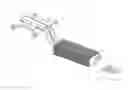
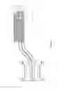
FIG. 1 is an exploded view of a heat sink and mounting bracket arrangement in accordance with a first embodiment of the present invention.
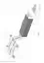
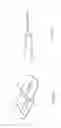
FIG. 2 is an oblique top view of a mounting bracket for the heat sink and mounting bracket arrangement in accordance with the first embodiment of the present invention.
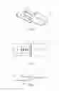
FIG. 3 is a top view of FIG. 2.
FIG. 4 is a sectional view taken along line 4-4 of FIG. 3.
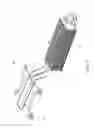
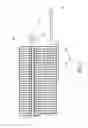
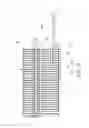
FIG. 5 is an oblique top view of the first embodiment of the present invention, illustrating heat pipes embedded in the radiation fin module and a heat transfer plate bonded to the heat pipes outside the radiation fin module.
FIG. 6 is a bottom view of FIG. 5.
FIG. 7 is a sectional view taken along line 7-7 of FIG. 6.
FIG. 8 is an oblique top view of a mounting bracket for the heat sink and mounting bracket arrangement in accordance with a second embodiment of the present invention.
FIG. 9 is a sectional view of the mounting bracket shown in FIG. 8.
FIG. 10 is a sectional view of the heat sink and mounting bracket arrangement in accordance with the second embodiment of the present invention.
FIG. 11 is an oblique top view of a mounting bracket for the heat sink and mounting bracket arrangement in accordance with a third embodiment of the present invention.
FIG. 12 is a sectional view of the mounting bracket shown in FIG. 11.
FIG. 13 is a sectional view of the heat sink and mounting bracket arrangement in accordance with the third embodiment of the present invention.
DETAILED DESCRIPTION OF THE PREFERRED EMBODIMENTS
Referring to FIGS. 1 and 2, a heat sink and mounting bracket arrangement in accordance with a first embodiment of the present invention is shown. The heat sink and mounting bracket arrangement comprises a radiation fin module 2, and a mounting bracket 1 connected to a rear end of the radiation fin module 2 in a tight fit manner. As illustrated in FIG. 3 and FIG. 4, the mounting bracket 1 is made from a metal plate sheet by stamping, comprising a bottom panel 11, an angled mounting panel 12 rearwardly extending from one end of the bottom panel 11, a mounting slot 121 cut through opposing top and bottom walls of the mounting panel 12, and an angled plug plate 13 forwardly extending from the bottom panel 11 adjacent to the angled mounting panel 12. Thus, the angled plug plate 13 extends in a direction opposite to the angled mounting panel 12. The radiation fin module 2 comprises a stack of radiation fins 21, and an insertion hole 211 located in one end of the stack of radiation fins 21. The angled plug plate 13 of the mounting bracket 1 is tightly press-fitted into the insertion hole 211, and thus the mounting bracket 1 and the radiation fin module 2 are tightly connected together (see FIG. 5).
The aforesaid mounting bracket 1 is tightly connected to the radiation fin module 2 by tightly press-fitting the angled plug plate 13 into the insertion hole 211. The mounting slot 121 of the mounting panel 12 of the mounting bracket 1 is adapted for the mounting of a fastening member (such as a screw bolt) to affix the tail end (the mounting bracket 1) of the radiation fin module 2 to a substrate (e.g. PC BOARD).
Referring to FIG. 6, the bottom panel 11 of the mounting bracket 1 is clamped on a bottom wall of the radiation fin module 2, and the angled plug plate 13 is tightly press-fitted into the insertion hole 211 of the radiation fin module 2, and thus the mounting bracket 1 and the radiation fin module 2 are tightly held down and clamped together.
Referring to FIG. 7, the angled plug plate 13 of the mounting bracket 1 comprises a row of ribs 131 located at an inner (bottom) wall thereof and spaced from one another corresponding to the gaps in between the radiation fins 21. Thus, after insertion of the angled plug plate 13 into the insertion hole 211, the ribs 131 are respectively engaged into the gaps in between the radiation fins 21, enhancing the connection tightness between the mounting bracket 1 and the radiation fin module 2 and effectively prohibiting separation between the angled plug plate 13 of the mounting bracket 1 and the insertion hole 211 of the radiation fin module 2.
Further, the angled plug plate 13 of the mounting bracket 1 is formed of a part of the metal plate sheet in the stamping process, leaving an opening 111 in the bottom panel 11.
In a second embodiment of the present invention, as shown in FIG. 8 and FIG. 9, two rows of ribs 113 are located at the top wall 112 of the bottom panel 11 and symmetrically disposed at two opposite lateral sides relative to the opening 111. In each row, the ribs 113 are spaced from one another corresponding to the gaps in between the radiation fins 21. Thus, after insertion of the angled plug plate 13 into the insertion hole 211, the ribs 113 at the top wall 112 of the bottom panel 11 and the ribs 131 at the angled plug plate 13 are respectively engaged into the gaps in between the radiation fins 21, enhancing the connection tightness between the mounting bracket 1 and the radiation fin module 2 and effectively prohibiting separation between the mounting bracket 1 and the radiation fin module 2.
In a third embodiment of the present invention, as shown in FIGS. 11-13, the bottom panel 11 and angled plug plate 13 of the mounting bracket 1 do not have the aforesaid ribs 113,131, however, the thickness of the angled plug plate 13 is slightly larger than the size of the insertion hole 211 of the radiation fin module 2. After insertion of the angled plug plate 13 into the insertion hole 211 of the radiation fin module 2 by force, the mounting bracket 1 and the radiation fin module 2 are tightly secured together (see FIG. 1).
The annexed drawings simply illustrate the technical features of the aforesaid three embodiments of the present invention. It is to be understood that various modifications and enhancements may be made without departing from the spirit and scope of the invention.
In conclusion, the invention provides a heat sink and mounting bracket arrangement, which comprises a radiation fin module 2, and a mounting bracket 1 press-fitted into and clamped on a rear end of the radiation fin module 2. The heat sink and mounting bracket arrangement further comprises at least one heat pipe 3. Each heat pipe 3 has the cold end thereof embedded in the radiation fin module 2, and the hot end thereof extending out of the radiation fin module 2 and bonded to a heat transfer plate 4 that is adapted for fastening to a heat source and absorbing waste heat from it. The heat transfer plate 4 has a plurality of mounting lugs 41 for mounting. The invention enables the mounting bracket to be fastened to the radiation fin module by press-fitting and clamping instead of the welding or adhesive bonding techniques used in the prior art designs.
Claims
What is claimed is:1. A heat sink and mounting bracket arrangement, comprising a radiation fin module, and a mounting bracket connected to a rear end of said radiation fin module, wherein said radiation fin module comprises a stack of radiation fins, and an insertion hole located in one end of said stack of radiation fins; said mounting bracket is made from a metal plate sheet by stamping, comprising a bottom panel clamped on said stack of radiation fins, an angled mounting panel rearwardly extending from one end of said bottom panel, a mounting slot cut through opposing top and bottom walls of said mounting panel for mounting a fastening member to affix said mounting bracket to an external substrate, and an angled plug plate forwardly extending from said bottom panel adjacent to said angled mounting panel and tightly press-fitted into said insertion hole of said radiation fin module.
2. The heat sink and mounting bracket arrangement as claimed in claim 1, wherein said bottom panel of said mounting bracket is clamped on a bottom wall of said radiation fin module.
3. The heat sink and mounting bracket arrangement as claimed in claim 1, wherein said mounting bracket further comprises a plurality of ribs located at an inner wall of said angled plug plate and respectively engaged in gaps in between said radiation fins of said radiation fin module.
4. The heat sink and mounting bracket arrangement as claimed in claim 1, wherein said mounting bracket further comprises an opening located in said bottom panel corresponding to said angled plug plate, and a plurality of ribs located at a top wall of said bottom panel and disposed at two opposite lateral sides relative to said opening and respectively engaged in gaps in between said radiation fins of said radiation fin module.
5. The heat sink and mounting bracket arrangement as claimed in claim 1, wherein said angled plug plate of said mounting bracket has a thickness slightly larger than the size of said insertion hole of said radiation fin module.
6. The heat sink and mounting bracket arrangement as claimed in claim 1, further comprising at least one heat pipe mounted in said radiation fin module, and a heat transfer plate connected with said at least one heat pipe outside said radiation fin module, each said heat pipe having a cold end thereof embedded in said stack of radiation fins of said radiation fin module and an opposing hot end extending out of said radiation fin module and bonded to said heat transfer plate.
Images & Drawings included:

Sources:
- United States Patent and Trademark Office - verify current appl. status at the USPTO↗
Recent applications in this class:
- » 20250093111 2025-03-20
HEAT DISSIPATION DEVICES FOR CHANNEL COOLING SECTION AND APPLICATION METHODS THEREOF - » 20250093110 2025-03-20
Heat Transfer System - » 20240280332 2024-08-22
TWO-PHASE IMMERSION-COOLING HEAT-DISSIPATION STRUCTURE HAVING SKIVED FINS - » 20240247883 2024-07-25
DEFORMABLE FIN HEAT EXCHANGER - » 20240247882 2024-07-25
LIQUID-COOLING HEAT DISSIPATION STRUCTURE HAVING NONLINEAR FIN ARRAY AND METHOD FOR MANUFACTURING THE SAME - » 20240142180 2024-05-02
Two-phase immersion-type heat dissipation structure having non-vertical fins - » 20230408212 2023-12-21
Method of manufacturing dehumidifier, dehumidification element, and dehumidifier including dehumidification element - » 20230408211 2023-12-21
HEAT EXCHANGER WITH TWO OPPOSITE AIRFLOWS - » 20230296328 2023-09-21
HEAT EXCHANGE SYSTEM - » 20230204305 2023-06-29
HEAT DISSIPATION MEMBER AND COOLING DEVICE