Intrusion detector and method for improved sensitivity
US20160154096A1
2016-06-02
14/510,394
2014-10-09
✅ Patent granted
US 9,841,499 B2
2017-12-12
-
-
Peter M Bythrow
Husch Blackwell LLP
2036-04-08
Abstract:
A motion detector includes a microwave-based module to detect movement. Intermediate processing circuitry is coupled to an output from the module. The processing circuitry is activated intermittently to produce first and second pulsed output signals. Cross-correlation circuitry processes the two signals to produce a motion indicating output signal.
Assignee:
- HONEYWELL INTERNATIONAL INC. 10,240 🇺🇸 Morristown, NJ, United States
Applicant:
Interested in similar patents?
Get notified when new applications in this technology area are published.
Classification:
G08B13/2491 » CPC further
Burglar, theft or intruder alarms; Electrical actuation by interference with electromagnetic field distribution Intrusion detection systems, i.e. where the body of an intruder causes the interference with the electromagnetic field
G08B29/185 » CPC further
Checking or monitoring of signalling or alarm systems; Prevention or correction of operating errors, e.g. preventing unauthorised operation; Prevention or correction of operating errors Signal analysis techniques for reducing or preventing false alarms or for enhancing the reliability of the system
G08B29/28 IPC
Checking or monitoring of signalling or alarm systems; Prevention or correction of operating errors, e.g. preventing unauthorised operation; Prevention or correction of operating errors; Calibration, including self-calibrating arrangements; Self-calibration, e.g. compensating for environmental drift or ageing of components by changing the gain of an amplifier
G01S7/28 » CPC further
Details of systems according to groups of systems according to group Details of pulse systems
G01S13/04 » CPC main
Systems using the reflection or reradiation of radio waves, e.g. radar systems; Analogous systems using reflection or reradiation of waves whose nature or wavelength is irrelevant or unspecified; Systems using reflection of radio waves, e.g. primary radar systems; Analogous systems Systems determining presence of a target
G08B13/24 IPC
Burglar, theft or intruder alarms; Electrical actuation by interference with electromagnetic field distribution
G08B29/18 IPC
Checking or monitoring of signalling or alarm systems; Prevention or correction of operating errors, e.g. preventing unauthorised operation Prevention or correction of operating errors
G01S7/285 » CPC further
Details of systems according to groups of systems according to group; Details of pulse systems Receivers
G01S13/56 » CPC further
Systems using the reflection or reradiation of radio waves, e.g. radar systems; Analogous systems using reflection or reradiation of waves whose nature or wavelength is irrelevant or unspecified; Systems using reflection of radio waves, e.g. primary radar systems; Analogous systems; Systems of measurement based on relative movement of target; Discriminating between fixed and moving objects or between objects moving at different speeds for presence detection
Description
FIELD
The application pertains to intrusion detectors used in monitoring regions of interest. More particularly, the application pertains to such detectors and associated methods which provide improved signal-to-noise ratios and enlarge the detection area in a region of interest without increased power consumption.
BACKGROUND
Motion detectors incorporating microwave technology are widely used in the field of security. There are two modules in this type of detector. One is a microwave detection module which radiates microwaves into a monitored area of space and receives reflected waves. If there are moving objects, the frequency of the reflected microwave is different from the radiated microwave. By mixing the received and radiated microwaves, we can get the difference frequency (also called intermediate frequency, IF). The other module is the IF signal processing module which will amplify, digitize and extract the IF signal.
If there is a person walking in the monitored area, then the detection module detects the frequency difference between transmitted and received microwaves, and outputs the corresponding IF frequency. The IF signals are amplified, sampled, and processed by hardware circuit and algorithms of the IF processing module to determine whether there has been an intrusion. A corresponding control output can then be generated.
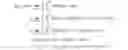
Typically, a prior art motion detector using microwave technology, illustrated in FIG. 1, includes a microwave sensor module 110, and an IF signal processing module 120. As illustrated in the diagram of FIG. 1, the sensor module 110 outputs an electrical IF signal by sensing the motion of a human body. Then, the IF signal is processed by the IF module 120. That signal is then identified by processing in the Digital Signal Processor (DSP). A corresponding control output signal can then be generated.
The circuit of FIG. 1 exhibits several problems. IF processing module 120 adds noise to the IF signal outputted by the microwave sensor module 110. Hence, it is very easy to miss alarms for weak signals, such as these signals generated by long range targets, or having a low scattering cross section area. Additionally, if the sensor module is battery-powered, the radiated microwave power can only have limited signal strength. Therefore, detector sensitivity is a problem at times.
BRIEF DESCRIPTION OF THE DRAWINGS
FIG. 1 illustrates a block diagram of a prior art system;
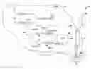
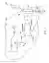
FIG. 2 is a block diagram of an embodiment hereof; and
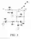
FIG. 3 is a schematic of an exemplary amplifier circuit.
DETAILED DESCRIPTION
While disclosed embodiments can take many different forms, specific embodiments thereof are shown in the drawings and will be described herein in detail with the understanding that the present disclosure is to be considered as an exemplification of the principles thereof as well as the best mode of practicing same, and is not intended to limit the application or claims to the specific embodiment illustrated.
In one aspect, embodiments hereof relate to the surveillance systems for detecting an intruder in a monitored area of space. More particularly embodiments disclose improvements for the signal processing method for intrusion sensors. More specifically a method for the intermediate signal amplifying processing is disclosed. Advantageously, this method can effectively improve the signal-to-noise ratio of microwave-type detection systems, and enlarge the detection area without increasing the power consumption for the microwave unit.
Disclosed embodiments incorporate cross-correlation methods to process an IF signal from a microwave-type intrusion sensor. This processing will produce motion indicating signals with substantially reduced noise compared to that generated by the sensor and subsequent amplifiers of the IF processing module.
In another aspect, the IF signal generated by microwave intrusion sensor is spit at a node into two signals. The two signals are separately and identically processed. Each of the signals is amplified and then sampled. This produces, two digital time sequences, S1(n) and S2(n). Cross-correlation processing of the signals can be carried out using a digital signal processor (DSP).
FIG. 2 illustrates a detector 20 in accordance herewith. Detector 20 is carried in a housing 22. The detector 20 includes a microwave-type intrusion sensor, module 26, which generates an output IF signal, labeled S0 in FIG. 2.
The signal S0 is in turn coupled to IF processing module 28. Module 28 includes first and second, substantially identical, amplifier/analog-to-digital converter strings 28-1 and 28-2. It will be understood that the use of two strings is exemplary only. Three or more strings could be used without departing from the spirit and scope hereof.
The two strings 28-1, 28-2 are coupled to DSP 30. Outputs from DSP 30 can be coupled to control circuits 32. It will be understood that the DSP 30 could be incorporated into and made a part of control circuits 32 without departing from the spirit and scope hereof.
Control circuits 32 can be implemented with hardwired circuits along with one or more programmed processors, and associated control software. The DSP 30 can be implemented, if desired, as a hardwired unit.
The control circuits 32 are coupled to an amplifier power supply 34, which can be energized by a battery B which also energizes other circuits of the detector 20. The control circuits 32 can be in wired or wireless communication with a displaced monitoring system 36. Detector 20 can be one of a plurality of such detectors which communicate with monitoring system 36.
There are at least two approaches to improve the sensitivity of microwave-type motion detectors. One way is to place a low noise amplifier (LNA) between receiving antenna and mixer, of the sensing module, such as module 26. Another way is to reduce the noise which will be added to the signal by subsequent processing circuits. Because the receiver antenna Rx is very close to the transmitter antenna Tx, their coupling is very strong. Hence, if a LNA is placed after the receiver antenna Rx, the LNA may be saturated. Therefore, the practical way to improve sensitivity is to reduce signal noise.
Sources of signal noise include circuit components, as well as the way in which various modules or components are operated. Surprisingly, despite the fact that the detector 20 incorporates two signal paths 28-1, -2, overall noise effects can be reduced in the embodiment 20. As illustrated in FIG. 2, N1 and N2 designate the noise generated by the first and second paths respectively. Due to the independence of the two paths, the two noise components are independent and stochastic. As a result of using cross-correlation processing, the two noise components N1, N2 can be cancelled out.
In further explanation, Let S1 and S2 be the output of the first and second paths respectively, their cross correlation function is:
R S 1 S 2 ( τ ) = lim T → ∞ 1 T ∫ 0 T S 1 ( t ) S 2 ( t - τ ) t = lim T → ∞ 1 T ∫ 0 T [ S 0 ( t ) + N 1 ( t ) ] [ S 0 ( t - τ ) + N 2 ( t - τ ) ] t = lim T → ∞ 1 T ∫ 0 T [ S 0 ( t ) S 0 ( t - τ ) + S 0 ( t ) N 2 ( t - τ ) + N 1 ( t ) S 0 ( t - τ ) + N 1 ( t ) N 2 ( t - τ ) ] t = R S D S D ( τ ) + R S D N 2 ( τ ) + R N 1 S D ( τ ) + R N 1 N 2 ( τ )
Where, N1 and N2 are zero-mean white Gaussian noises, in signal S0, N1 and N2 are uncorrelated with each other, so RSDN2 (τ), RN1ND (τ) and RN1N2 (τ) equal to zero.
In summary, in addition to reducing noise generated by the circuit components 28-1, -2, by applying the cross-correlation method to process IF signal as discussed above, the disclosed detectors will have an improved detecting sensitivity, which makes the sensor detection range/area larger. Further, by applying the cross-correlation to process IF signals, and for a given detection range/area, such detectors can be expected to have fewer false alarms. As a result of applying the cross-correlation method to process IF signals, for a given detection range/area, the detector needs less radiated power, and less power dissipation.
FIG. 3 illustrates an exemplary amplifier circuit 40 usable in detector 20. Amplifier 40 includes an operational amplifier 42, for example an LM324A, as well as a combination of resistors 42a, b, and c. Capacitors 44a, b, c, d complete the circuit 40.
Since sensors, such as sensor 26, operate based on a principle of Doppler shift, and due to slow moving objects, in the field of view, the Doppler frequency is very low, on the order of tens of Hertz. Hence implementing the circuit 42 with an operational amplifier is a desirable solution.
However the resistors of the amplifier 40 do in fact introduce additional noise into the signals of each of the strings 28-1, -2. Surprisingly, the noise introduced by the amplifiers into each of the uncorrelated paths 28-1, -2 can be canceled out by the above described cross-correlation processing carried out by DSP 30.
Using a controllable amplifier power supply, such as supply 34, to reduce power required by the detector 20, the amplifiers, such as amplifier 40, can be operated in a pulsed mode. In this mode, the amplifiers, such as amplifier 40 inject additional noise into each of the associated signals, such as S1, S2. The module 26 can also be operated intermittently for similar reasons.
The above described cross-correlation processing can be expected to cancel such amplifier generated noise.
From the foregoing, it will be observed that numerous variations and modifications may be effected without departing from the spirit and scope hereof. It is to be understood that no limitation with respect to the specific apparatus illustrated herein is intended or should be inferred. It is, of course, intended to cover by the appended claims all such modifications as fall within the scope of the claims. Further, logic flows depicted in the figures do not require the particular order shown, or sequential order, to achieve desirable results. Other steps may be provided, or steps may be eliminated, from the described flows, and other components may be add to, or removed from the described embodiments.
Claims
1. A motion detector comprising:
a module to detect movement;
intermediate processing circuitry coupled to an output from the module which is activated intermittently to produce first and second pulsed output signals;
cross-correlation circuitry to process the two signals to produce a motion indicating output signal.
2. A detector as in claim 1 where the processing circuitry includes firs, second amplifiers to amplify a sensor output signal.
3. A detector as in claim 2 which includes an operational amplifier to amplify each module output signal.
4. A detector as in claim 1 where the cross-correlation circuitry includes a digital signal processor.
5. A detector as in claim 1 which includes control circuits to switch at least the intermediate processing circuits between first and second operational states.
6. A detector as in claim 5 where one of the states comprises a no power state.
7. A detector as in claim 5 which includes switchable power supply circuits.
8. A detector as in claim 1 which includes a housing that carries the module, the processing circuitry, and the cross-correlation circuits.
9. A detector as in claim 8 and which includes control circuits to switch at least the intermediate processing circuits between first and second operational states, and where one of the states is a no power state.
10. A detector as in claim 9 which includes transmission circuits coupled to the control circuits to communicate with a displaced location by one of a wired or wireless medium.
11. A detector as in claim 10 which includes a battery coupled to at least the control circuits
12. A method comprising:
generating a selected signal indicative of motion in a predetermined sensing window;
establishing first and second separate amplified indicia of the selected signal;
cross-correlation processing of the separate amplified indicia; and
determining the presence of motion from the processed indicia.
13. A method as in claim 12 which includes converting amplified indicia to digital pulse trains.
14. A detector as in claim 12 which includes feeding digital pulse trains to the cross-correlation circuits.
15. A detector as in claim 14 which includes producing intermittent digital pulse trains.
16. A detector as in claim 15 which includes generating a movement indicating output signal.
17. A detector as in claim 15 which includes transmitting the output signal, via a wired or wireless medium to a displaced location.
18. A detector as in claim 17 which includes providing one of hardwired or software implemented digital signal processing.
19. A motion detector comprising:
a micro-wave based module to detect movement;
intermediate processing circuitry coupled to an output from the module which to produce first and second, separate, output signals;
cross-correlation circuitry to process the two signals to produce a motion indicating output signal.
20. A detector as in claim 19 where the intermediate processing circuitry includes first and second processing elements where each element includes an amplifier series coupled to an analog-to-digital converter.
Images & Drawings included:
Sources:
- United States Patent and Trademark Office - verify current appl. status at the USPTO↗
Recent applications in this class:
- » 20250271567 2025-08-28
SEAT OCCUPANCY SENSOR SYSTEM FOR VEHICLES AND METHOD OF USING THE SAME - » 20250244459 2025-07-31
OCCUPANT DETECTION DEVICE - » 20250216532 2025-07-03
DEVICE AND METHOD FOR DETECTING TARGET OBJECT - » 20250216531 2025-07-03
ELECTRONIC DEVICE, METHOD FOR CONTROLLING ELECTRONIC DEVICE, AND PROGRAM - » 20250199149 2025-06-19
LOCALIZATION TO MAPS FOR AUTONOMOUS AND SEMI-AUTONOMOUS SYSTEMS AND APPLICATIONS - » 20250180723 2025-06-05
DETECTION DEVICE AND METHOD OF OPERATING SAME - » 20250180722 2025-06-05
OCCUPANT DETECTION APPARATUS AND OCCUPANT DETECTION METHOD - » 20250180721 2025-06-05
REGISTRATION OF A SENSING TARGET - » 20250147165 2025-05-08
METHOD AND SYSTEM FOR DETECTING A SEAT OCCUPANCY STATE OF A SEATING ARRANGEMENT ON THE BASIS OF RADAR POINT CLOUDS - » 20250138174 2025-05-01
METHOD FOR ACTIVATING A VEHICLE FUNCTION AND ASSOCIATED ACTIVATION DEVICE
Recent applications for this Assignee:
- » 20200347311 2020-11-05
Process for natural gas production - » 20200222851 2020-07-16
Integrated mercaptan extraction and/or sweetening processes combined with thermal oxidation and flue gas treatment - » 20190174102 2019-06-06
Systems and methods for automatic video recording - » 20190136108 2019-05-09
STABILIZED IODOCARBON COMPOSITIONS - » 20190120659 2019-04-25
Differential hall magnet polarity detection for AMR 360 degree sensor - » 20190104161 2019-04-04
Systems and methods for directly accessing video data streams and data between devices in a video surveillance system - » 20190084905 2019-03-21
NOVEL PROCESS FOR MANUFACTURING 2-CHLORO-3,3,3-TRIFLUOROPROPENE FROM 1,2-DICHLORO-3,3,3-TRIFLUOROPROPENE - » 20190056529 2019-02-21
Anti-fog and anti-reflective dual-functional coating for optical articles - » 20190047927 2019-02-14
Methods for removing halogenated ethylene impurities in 2, 3, 3, 3-tetrafluoropropene product - » 20190005805 2019-01-03
Systems and methods for delaying or activating a blowout device or a purge device in a sampling pipe network of an aspirated smoke detection system