Imaging lens system
US20160154208A1
2016-06-02
14/701,638
2015-05-01
✅ Patent granted
US 9,759,890 B2
2017-09-12
-
-
Bumsuk Won | Wen Huang
Na Xu | IPro, PLLC
2035-12-28
Abstract:
An imaging lens system includes, arranged in succession from an object side to an image side, an aperture stop S, a first lens L1 having a positive refractive power, a second lens L2 having a negative refractive power, a third lens L3 having a positive refractive power, a fourth lens L4 having a positive refractive power, and a fifth lens L5 having a negative refractive power. 0.70≦f1/f≦0.85; −1.15≦(R1+R2)/(R1−R2)≦−1.00; −0.55≦(R3+R4)/(R3−R4)≦−0.20; 0.09≦d8/f≦0.15; f/f1 is respectively a focal length of the lens system LA or lens L1; R1/R2 is respectively a curvature radius of the object/image side of the lens L1; R3/R4 is a curvature radius of the object/image side of the lens L2; d8 is an axial distance between the image side of the lens L4 to the object side of the lens L5.
Assignee:
- AAC TECHNOLOGIES PTE. LTD 958 🇸🇬 Singapore, Singapore
- AAC Technologies Pte. Ltd. 343 🇸🇬 Singapore city, Singapore
Applicant:
Interested in similar patents?
Get notified when new applications in this technology area are published.
Classification:
G02B13/005 » CPC main
Optical objectives specially designed for the purposes specified below; Miniaturised objectives for electronic devices, e.g. portable telephones, webcams, PDAs, small digital cameras characterised by the lens design having spherical lenses only
G02B13/00 IPC
Optical objectives specially designed for the purposes specified below
G02B9/60 » CPC further
Optical objectives characterised both by the number of the components and their arrangements according to their sign, i.e. + or - having five components only
G02B13/0045 » CPC main
Optical objectives specially designed for the purposes specified below; Miniaturised objectives for electronic devices, e.g. portable telephones, webcams, PDAs, small digital cameras characterised by the lens design having at least one aspherical surface having five or more lenses
Description
FIELD OF THE INVENTION
The present invention relates to an imaging lens system, and more particularly to an imaging lens system with high imaging performance and suitable for installation into an image input device of a portable telephone or personal computer, a digital camera, a CCD or CMOS camera used for monitoring purposes, a surveying device, or similar.
DESCRIPTION OF RELATED ART
Imaging apparatuses using solid-state image sensing devices such as CCD (Charge-Coupled Device) type image sensors and CMOS (Complementary Metal-Oxide Semiconductor) type image sensors include digital still cameras, digital video cameras, and the like. Imaging apparatuses using such solid-state image sensing devices are suitable for miniaturization, and hence have recently been widely used in compact information terminals such as cellular phone sets.
With increases in the miniaturization and pixel density of solid-state image sensing devices, demands have arisen for smaller and higher-performance imaging lenses to be mounted in these imaging apparatuses. In this disclosure, an imaging lenses system used for such an application includes, arranged in succession from an object side to an image side: a first lens having a positive refracting power, a second lens having a negative refractive power, a third lens having a positive refractive power, a fourth lens having a positive refractive power, and a fifth lens having a negative refractive power.
Japanese Patent Application Publication No. JP2013-222172 discloses an imaging lens system in embodiments 1-9, having the aforementioned five lenses, in which, the first and second lenses are not properly shaped, therefore it may weaken the miniaturization, wide-angle and the effect of realizing TTL/IH>1.71, and 2ω<71.1°.
Japanese Patent Application Publication No. JP2014-044372 discloses another type of imaging lens system in its embodiments 1-6, which also includes the aforementioned five lenses, while the refractive power of the first lens, and the shape of the second lens re not configured properly, so the effect of achieving 2ω<71.1° and a wide angle may not be satisfying.
Accordingly, an improved imaging lens which can overcome the disadvantages described above is desired.
BRIEF DESCRIPTION OF THE DRAWINGS
Many aspects of the embodiment can be better understood with reference to the following drawings. The components in the drawing are not necessarily drawn to scale, the emphasis instead being placed upon clearly illustrating the principles of the present disclosure. Moreover, in the drawings, like reference numerals designate corresponding parts throughout the several views.
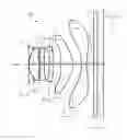
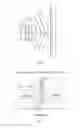
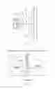
FIG. 1 is an illustrative structure of an imaging lens system related to the present invention;
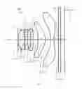
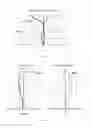
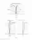
FIG. 2 is an illustrative structure of an imaging lens system related to a first embodiment of the present disclosure;
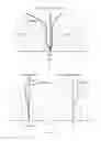
FIG. 3 is an aberration diagram showing spherical aberration (on-axis chromatic aberration) of the imaging lens system of the first embodiment;
FIG. 4 is a ratio chromatic aberration diagram of the imaging lens system of the first embodiment;
FIG. 5 is an aberration diagram showing the curvature of field and the distortion of the imaging lens system of the first embodiment.
FIG. 6 is an illustrative structure of an imaging lens system related to a second embodiment of the present disclosure;
FIG. 7 is an aberration diagram showing spherical aberration (on-axis chromatic aberration) of the imaging lens system of the second embodiment;
FIG. 8 is a ratio chromatic aberration diagram of the imaging lens system of the second embodiment;
FIG. 9 is an aberration diagram showing the curvature of field and the distortion of the imaging lens system of the second embodiment;
FIG. 10 is an illustrative structure of an imaging lens system related to a third embodiment of the present disclosure;
FIG. 11 is an aberration diagram showing spherical aberration (on-axis chromatic aberration) of the imaging lens system of the third embodiment;
FIG. 12 is a ratio chromatic aberration diagram of the imaging lens system of the third embodiment;
FIG. 13 is an aberration diagram showing the curvature of field and the distortion of the imaging lens system of the third embodiment;
FIG. 14 is an illustrative structure of an imaging lens system related to a fourth embodiment of the present disclosure;
FIG. 15 is an aberration diagram showing spherical aberration (on-axis chromatic aberration) of the imaging lens system of the fourth embodiment;
FIG. 16 is a ratio chromatic aberration diagram of the imaging lens system of the fourth embodiment;
FIG. 17 is an aberration diagram showing the curvature of field and the distortion of the imaging lens system of the fourth embodiment.
DETAILED DESCRIPTION OF THE EXEMPLARY EMBODIMENTS
The present invention will hereinafter be described in detail with reference to several embodiments.
Referring to FIG. 1, an imaging lens system LA related to the present invention includes, from an object side to an image side, an aperture stop S1, a first lens L1, a second lens L2, a third lens L3, a fourth lens L4, and a fifth lens L5. A glass plate GF is arranged between the fifth lens L5 and an image surface. The glass plate GF may be a cover glass, an IR filter, or a low frequency filter. Alternatively, the glass plate may be arranged at other positions.
The first lens L1 has a positive refractive power, the second lens L2 has a negative refractive power, the third lens L3 has a positive refractive power, the fourth lens L4 has a positive refractive power, and the fifth lens L5 has a negative refractive power. With the configuration of the refractive powers of the lenses, the imaging lens system LA may be miniaturized. Further, for correcting aberrations appropriately, these five lenses are configured to be aspherical.
The imaging lens system LA satisfies the following conditions (1)-(4):
0.70≦f1/f≦0.85 (1)
−1.15≦(R1+R2)/(R1−R2)≦−1.00 (2)
−0.55≦(R3+R4)/(R3−R4)≦−0.20 (3)
0.09≦d8/f≦0.15 (4)
Where:
-
- f is a focal length of the imaging lens system LA;
- f1 is a focal length of the first lens L1;
- R1 is a curvature radius of the object side of the first lens L1;
- R2 is a curvature radius of the image side of the first lens L1.
- R3 is a curvature radius of the object side of the second lens L2;
- R4 is a curvature radius of the image side of the second lens L2;
- d8 is an axial distance between the image side of the fourth lens L4 to the object side of fifth lens L5.
Condition (1) prescribes the positive refractive power of the second lens L2. If the value excesses the minimum limit, although it facilitates the miniaturization of the imaging lens system LA, the positive refractive power of the first lens L1 is too powerful to correct image aberrations. If the value excesses the maximum limit, the positive refractive power of the first lens L1 is weakened and it is difficult to miniaturize the imaging lens system LA.
Condition (2) prescribes the shape of the first lens L1. If the value fails to satisfy this condition, with the miniaturization and wide-angle development of the imaging lens system LA, it is difficult to correct the high order aberrations, for example spherical aberrations.
Condition (3) prescribes the shape of the second lens L2. If the value fails to satisfy this condition, with the miniaturization and wide-angle development of the imaging lens system LA, it is difficult to correct the on-axis chromatic aberrations.
Condition (4) prescribes the ratio of the distance from the image side of the fourth lens L4 to the object side of fifth lens L5, and the focal length of the imaging lens system LA. If the value fails to satisfy this condition, it adds difficulties to the miniaturization and wide-angle development of the imaging lens system LA.
Further, the imaging lens system LA satisfies the following conditions (5):
0.12≦d6/f≦0.15 (5)
Where:
-
- f is the focal length of the imaging lens system LA;
- d6 is an axial distance between the image side surface of the third lens L3 and the object side surface of the fourth lens L4.
Condition (5) prescribes ratio of the distance from image side surface of the third lens L3 and the object side surface of the fourth lens L4, and the focal length of the imaging lens system LA. If the value fails to satisfy this condition, it adds difficulties to the miniaturization and wide-angle development of the imaging lens system LA.
Further, the imaging lens system LA satisfies the following condition (6):
−2.50≦f2/f≦−1.00 (6)
Where:
-
- f is the focal length of the imaging lens system LA;
- f2 is a focal length of the second lens L2.
Condition (6) prescribes the negative refractive power of the second lens L2. If the value fails to satisfy this condition, with the miniaturization and wide-angle development of the imaging lens system LA, it is difficult to correct the aberrations, for example off-axis and on-axis chromatic aberrations.
The third lens L3 has a positive refractive power, and the imaging lens system LA further satisfies the following condition (7)-(8):
f3/f≧50.00 (7)
(R5+R6)/(R5−R6)≦−8.00 (8)
Where:
-
- f is the focal length of the imaging lens system LA;
- f3 is a focal length of the third lens L3;
- f5 is a focal lens of the fifth lens L5;
- f6 is a focal lens of the sixth lens L6.
Condition (7) prescribes the positive refractive power of the third lens L3. When the value satisfies this condition, it may not only efficiently help to the miniaturization and wide-angle development of the imaging lens system LA, but also facilitate correcting the aberrations, for example off-axis and on-axis chromatic aberrations.
Condition (8) prescribes the shape of the third lens L3. When the value satisfies this condition, with the miniaturization and wide-angle development of the imaging lens system LA, it may efficiently help to the miniaturization and wide-angle development of the imaging lens system LA.
By virtue of the configurations and conditions set forth in the forgoing description, an improved imaging lens system LA having the characteristics of wide-angle, miniaturization, TTL/IH≦1.40, 2ω≧78°, and Fno (F number)≦2.2, is accordingly obtained.
Hereinafter, detailed embodiments will be described to test and verify the conditions set forth in the above descriptions.
The parameters of the imaging lens system LA are defined as follows, and the unit of each of the distance, radius, and thickness is millimeter (mm).
-
- f: the focal length of the imaging lens system LA;
- f1: the focal length of the first lens L1;
- f2: the focal lens of the second lens L2;
- f3: the focal lens of the third lens L3;
- f4: the focal lens of the fourth lens L4;
- f5: the focal lens of the fifth lens L5;
- Fno: F number
- 2ω: full visual angle
- S1: aperture stop
- R: curvature radius
- R1: the curvature radius of the object side surface of the first lens L1;
- R2: the curvature radius of the image side surface of the first lens L1;
- R3: the curvature radius of the object side surface of the second lens L2;
- R4: the curvature radius of the image side surface of the second lens L2;
- R5: the curvature radius of the object side surface of the third lens L3;
- R6: the curvature radius of the image side surface of the third lens L3;
- R7: the curvature radius of the object side surface of the fourth lens L4;
- R8: the curvature radius of the image side surface of the fourth lens L4;
- R9: the curvature radius of the object side surface of the fifth lens L5;
- R10: the curvature radius of the image side surface of the fifth lens L5;
- R11: the curvature radius of the object side surface of the glass plate GF;
- R12: the curvature radius of the image side surface of the glass plate GF;
- d: axial thickness of the lens, or distance between lenses;
- d0: the axial distance between the aperture stop S1 and the object side surface of the first lens L1;
- d1: the axial thickness of the first lens L1;
- d2: the axial distance between the image side surface of the first lens L1 and the object side surface of the second lens L2;
- d3: the axial thickness of the second lens L2;
- d4: the axial distance between the image side surface of the second lens L2 and the object side surface of the third lens L3;
- d5: the axial thickness of the third lens L3;
- d6: the axial distance between the image side surface of the third lens L3 and the object side surface of the fourth lens L4;
- d7: the axial distance of the fourth lens L4;
- d8: the axial distance between the image side surface of the fourth lens L4 and the object side surface of the fifth lens L5;
- d9: the axial thickness of the fifth lens L5;
- d10: the axial distance between the image side surface of the fifth lens L5 and the object side surface of the glass plate GF;
- d11: the axial thickness of the glass plate GF;
- d12: the axial distance between the image side surface of the glass plate GF and the image surface;
- nd: d line refraction index
- nd1: d line refraction index of the first lens L1;
- nd2: d line refraction index of the second lens L2;
- nd3: d line refraction index of the third lens L3;
- nd4: d line refraction index of the fourth lens L4;
- nd5: d line refraction index of the fifth lens L5;
- nd6: d line refraction index of the glass plate GF;
- υ: abbe number
- υ1: abbe number of the first lens L1;
- υ2: abbe number of the second lens L2;
- υ3: abbe number of the third lens L3;
- υ4: abbe number of the fourth lens L4;
- υ5: abbe number of the fifth lens L5;
- υ6: abbe number of the glass plate GF;
- TTL: the axial distance between the object side surface of the first lens L1 and the image plane (total track length);
- LB: the axial distance between the image side surface of the fifth lens L5 and the image surface (including the axial thickness of the glass plate GF);
- IH: image height.
y=(x2/R)/[1+{1−(k+1)(x2/R2)}1/2]+A4x4+A6x6+A8x8+A10x10+A12 x12+A14x14+A16x16 (Condition 13)
-
- Where, R is the axial curvature radius, k is the conic coefficient, A4˜A16 are aspherical coefficients.
Optionally, each aspherical surface of each lens could be obtained according to condition (13). Of course, the aspherical surface may also be obtained according to other condition.
Embodiment 1
FIG. 2 shows an imaging lens system LA in accordance with Embodiment 1 of the present invention. Table 1 shows the detailed optical data of Embodiment 1. The conic coefficient and aspherical coefficient of the surfaces of the lenses of Embodiment 1 are listed in Table 2.
| TABLE 1 | ||||
| R | d | nd | νd | |
| S1 | ∞ | d0 = | −0.250 | ||||
| R1 | 1.42086 | d1 = | 0.552 | nd1 | 1.5441 | ν1 | 56.12 |
| R2 | 114.06203 | d2 = | 0.066 | ||||
| R3 | −5.28186 | d3 = | 0.225 | nd2 | 1.6510 | ν2 | 21.51 |
| R4 | 15.69255 | d4 = | 0.255 | ||||
| R5 | 11.40793 | d5 = | 0.235 | nd3 | 1.6510 | ν3 | 21.51 |
| R6 | 11.54192 | d6 = | 0.417 | ||||
| R7 | −4.80314 | d7 = | 0.657 | nd4 | 1.5441 | ν4 | 56.12 |
| R8 | −1.11946 | d8 = | 0.467 | ||||
| R9 | −2.58104 | d9 = | 0.272 | nd5 | 1.5441 | ν5 | 56.12 |
| R10 | 1.95912 | d10 = | 0.400 | ||||
| R11 | ∞ | d11 = | 0.210 | nd6 | 1.5168 | ν6 | 64.17 |
| R12 | ∞ | d12 = | 0.341 | ||||
| TABLE 2 | ||
| conic coefficient | aspherical coefficient |
| k | A4 | A6 | A8 | A10 | A12 | A14 | A16 | |
| R1 | 6.8146E−02 | −1.1921E−02 | 2.0851E−02 | −8.5269E−02 | 2.1275E−02 | 3.4900E−02 | 2.2141E−02 | −1.2501E−01 |
| R2 | 0.0000E+00 | −2.2810E−02 | −1.3024E−02 | 8.8008E−02 | −1.3505E−01 | −1.2073E−01 | 6.2492E−03 | 8.2286E−02 |
| R3 | 0.0000E+00 | 6.8314E−02 | 5.6668E−02 | 7.9184E−03 | −4.0275E−02 | −8.4171E−02 | −7.0973E−02 | 1.4224E−01 |
| R4 | −3.8793E+02 | 7.2878E−02 | 2.2776E−02 | −3.4173E−02 | 7.7336E−02 | −8.7613E−02 | −4.8772E−02 | 7.1592E−02 |
| R5 | −2.5353E+02 | −2.4977E−01 | −3.5405E−02 | −1.0712E−01 | 1.9118E−02 | 2.5398E−01 | 2.4167E−01 | −2.6535E−01 |
| R6 | 1.1637E+02 | −1.9958E−01 | −4.8390E−02 | 1.5556E−02 | 4.3468E−02 | 3.8021E−02 | 3.9750E−02 | 3.2725E−02 |
| R7 | 7.7631E+00 | −7.1962E−04 | −1.4944E−02 | −3.2077E−02 | 6.2996E−03 | 4.3361E−03 | 1.0020E−03 | −6.6594E−04 |
| R8 | −3.8572E+00 | −7.6404E−02 | 8.0780E−02 | −3.6430E−02 | 7.5631E−03 | −3.3522E−04 | 4.0454E−04 | −2.3129E−04 |
| R9 | −3.0986E+00 | −4.5210E−02 | 1.2481E−02 | 7.2775E−04 | −2.3569E−04 | −8.7006E−06 | −6.1753E−08 | 1.3877E−06 |
| R10 | −1.6962E+01 | −5.9473E−02 | 1.8896E−02 | −4.2178E−03 | 5.1014E−04 | −3.2020E−05 | −4.9603E−07 | 2.9298E−07 |
Referring subsequent Table 9, it shows all the parameters of the imaging lens system of the embodiments corresponding to conditions (1)-(8). As shown in Table 7, the imaging lens system LA of Embodiment 1 satisfies all of the conditions (1)-(8). The spherical aberration (on-axis chromatic aberration) of the imaging lens system LA of Embodiment 1 is shown in FIG. 3. The ratio chromatic aberration is shown in FIG. 4. The curvature of field and the distortion aberration are shown in FIG. 5. Wherein, S shows the curvature of field corresponding to sagittal image surface, and T shows the curvature of field corresponding to tangential image surface, and the embodiments 2-4 are the same. By virtue of the configuration, the imaging lens system LA of Embodiment 1 has the characteristics of wide-angle, miniaturization, 2ω=83.0°, TTL/IH=1.327, and Fno=2.05, and according to FIG. 3-FIG. 5, the good optical performance of the imaging lens system LA can be seen.
Embodiment 2
FIG. 6 shows an imaging lens system LA in accordance with Embodiment 2 of the present invention. Table 3 shows the detailed optical data of Embodiment 2. The conic coefficient and aspherical coefficient of the surfaces of the lenses of Embodiment 2 are listed in Table 4.
| TABLE 3 | ||||
| R | d | nd | νd | |
| S1 | ∞ | d0 = | −0.250 | ||||
| R1 | 1.40733 | d1 = | 0.563 | nd1 | 1.5441 | ν1 | 56.12 |
| R2 | 97.30522 | d2 = | 0.069 | ||||
| R3 | −5.31456 | d3 = | 0.233 | nd2 | 1.6510 | ν2 | 21.51 |
| R4 | 14.96478 | d4 = | 0.260 | ||||
| R5 | 11.48369 | d5 = | 0.234 | nd3 | 1.6510 | ν3 | 21.51 |
| R6 | 11.53410 | d6 = | 0.431 | ||||
| R7 | −4.74190 | d7 = | 0.651 | nd4 | 1.5441 | ν4 | 56.12 |
| R8 | −1.11294 | d8 = | 0.397 | ||||
| R9 | −2.51163 | d9 = | 0.323 | nd5 | 1.5441 | ν5 | 56.12 |
| R10 | 1.92895 | d10 = | 0.400 | ||||
| R11 | ∞ | d11 = | 0.210 | nd6 | 1.5168 | ν6 | 64.17 |
| R12 | ∞ | d12 = | 0.399 | ||||
| TABLE 4 | ||
| conic | ||
| coefficient | aspherical coefficient |
| k | A4 | A6 | A8 | A10 | A12 | A14 | A16 | |
| R1 | 5.0394E−02 | −1.5259E−02 | 1.9908E−02 | −8.5505E−02 | 2.1491E−02 | 3.5672E−02 | 2.3807E−02 | −1.2155E−01 |
| R2 | 0.0000E+00 | −2.2612E−02 | −1.2842E−02 | 8.6938E−02 | −1.3373E−01 | −1.1992E−01 | 6.5231E−03 | 8.1558E−02 |
| R3 | 0.0000E+00 | 6.9400E−02 | 5.7249E−02 | 7.6388E−03 | −4.0952E−02 | −8.4712E−02 | −7.1082E−02 | 1.4278E−01 |
| R4 | −3.9101E+02 | 7.1821E−02 | 2.1664E−02 | −3.4202E−02 | 7.7906E−02 | −8.6970E−02 | −4.8259E−02 | 7.1895E−02 |
| R5 | −2.5545E+02 | −2.4947E−02 | −3.4962E−02 | −1.0711E−01 | 1.8831E−02 | 2.5360E−01 | 2.4130E−01 | −2.6580E−01 |
| R6 | 1.1699E+02 | −1.9945E−02 | −4.8122E−02 | 1.5901E−02 | 4.3674E−02 | 3.8077E−02 | 3.9719E−02 | 3.2721E−02 |
| R7 | 8.3415E+00 | −5.4723E−02 | −1.4808E−02 | −3.1729E−02 | 6.5223E−03 | 4.3225E−03 | 7.8654E−04 | −1.0271E−03 |
| R8 | −3.7787E+00 | −7.5908E−02 | 8.0616E−02 | −3.6537E−02 | 7.5320E−03 | −3.4050E−04 | 4.0700E−04 | −2.2804E−04 |
| R9 | −3.1014E+00 | −4.5122E−02 | 1.2507E−02 | 7.3281E−04 | −2.3478E−04 | −8.5619E−06 | −6.1620E−06 | 1.3863E−06 |
| R10 | −1.5104E+01 | −5.9732E−02 | 1.6860E−02 | −4.2235E−03 | 5.0925E−04 | −3.2156E−05 | −5.1754E−07 | 2.8908E−07 |
As shown in Table 9, the imaging lens system LA of Embodiment 2 satisfies all of the conditions (1)-(8). The spherical aberration (on-axis chromatic aberration) of the imaging lens system LA of Embodiment 2 is shown in FIG. 7. The ratio chromatic aberration is shown in FIG. 8. The curvature of field and the distortion aberration are shown in FIG. 9. By virtue of the configuration, the imaging lens system LA of Embodiment 2 has the characteristics of wide-angle, miniaturization, 2ω=80.8°, TTL/IH=1.350, and Fno=2.05, and according to FIG. 7-FIG. 9, the good optical performance of the imaging lens system LA can be seen.
Embodiment 3
FIG. 10 shows an imaging lens system LA in accordance with Embodiment 3 of the present invention. Table 5 shows the detailed optical data of Embodiment 3. The conic coefficient and aspherical coefficient of the surfaces of the lenses of Embodiment 3 are listed in Table 6.
| TABLE 5 | ||||
| R | d | nd | νd | |
| S1 | ∞ | d0 = | −0.250 | ||||
| R1 | 1.39812 | d1 = | 0.553 | nd1 | 1.5441 | ν1 | 56.12 |
| R2 | 26.84025 | d2 = | 0.062 | ||||
| R3 | −5.70998 | d3 = | 0.229 | nd2 | 1.6510 | ν2 | 21.51 |
| R4 | 17.13039 | d4 = | 0.266 | ||||
| R5 | 11.33510 | d5 = | 0.231 | nd3 | 1.6510 | ν3 | 21.51 |
| R6 | 11.39630 | d6 = | 0.434 | ||||
| R7 | −4.83846 | d7 = | 0.651 | nd4 | 1.5441 | ν4 | 56.12 |
| R8 | −1.11885 | d8 = | 0.436 | ||||
| R9 | −2.44809 | d9 = | 0.300 | nd5 | 1.5441 | ν5 | 56.12 |
| R10 | 1.94609 | d10 = | 0.400 | ||||
| R11 | ∞ | d11 = | 0.210 | nd6 | 1.5168 | ν6 | 64.17 |
| R12 | ∞ | d12 = | 0.343 | ||||
| TABLE 6 | ||
| conic | ||
| coefficient | aspherical coefficient |
| k | A4 | A6 | A8 | A10 | A12 | A14 | A16 | |
| R1 | 5.0293E−02 | −1.6648E−02 | 2.0914E−02 | −8.3964E−02 | 2.2871E−02 | 3.6796E−02 | 2.4713E−02 | −1.2102E−01 |
| R2 | 0.0000E+00 | −2.3587E−02 | −1.3028E−02 | 8.6541E−02 | −1.3371E−01 | −1.1902E−01 | 7.9135E−03 | 8.3475E−02 |
| R3 | 0.0000E+00 | 6.7753E−02 | 5.6707E−02 | 7.9329E−03 | −4.0681E−02 | −8.4743E−02 | −7.1399E−02 | 1.4226E−01 |
| R4 | −7.4481E+02 | 7.4241E−02 | 2.3237E−02 | −3.4108E−02 | 7.7844E−02 | −8.7183E−02 | −4.8408E−02 | 7.1656E−02 |
| R5 | −1.7288E+02 | −2.4808E−01 | −3.4336E−02 | −1.0686E−01 | 1.8882E−02 | 2.5370E−01 | 2.4159E−01 | −2.6507E−01 |
| R6 | 1.1630E+02 | −1.9963E−01 | −4.9787E−02 | 1.4629E−02 | 4.3659E−02 | 3.9021E−02 | 4.1244E−02 | 3.4483E−02 |
| R7 | 8.3073E+00 | −3.6356E−03 | −1.4810E−02 | −3.1525E−02 | 6.5819E−03 | 4.2367E−03 | 5.9461E−04 | −1.2830E−03 |
| R8 | −3.9564E+00 | −7.6679E−02 | 8.0420E−02 | −3.6601E−02 | 7.4974E−03 | −3.5697E−04 | 3.9863E−04 | −2.3187E−04 |
| R9 | −3.0811E+00 | −4.5194E−02 | 1.2486E−02 | 7.3211E−04 | −2.3459E−04 | −8.4529E−06 | −6.1302E−06 | 1.3923E−06 |
| R10 | −1.8602E+01 | −5.9358E−02 | 1.6922E−02 | −4.2148E−03 | 5.1034E−04 | −3.2042E−05 | −5.0741E−07 | 2.8955E−07 |
Referring to Tables 5-6, and together with Table 9, the imaging lens system LA of Embodiment 3 satisfies conditions (1)˜(8). The spherical aberration (on-axis chromatic aberration) of the imaging lens system LA of embodiment 3 is shown in FIG. 11. The ratio chromatic aberration is shown in FIG. 12. The curvature of field and the distortion aberration are shown in FIG. 13. By virtue of the configuration, the imaging lens system LA of Embodiment 3 has the characteristics of wide-angle, miniaturization, 2ω=82.1°, TTL/IH=1.333 mm, and Fno=2.05. According to FIG. 11-FIG. 13, the good optical performance of the imaging lens system LA can be seen.
Embodiment 4
FIG. 14 shows an imaging lens system LA in accordance with Embodiment 4 of the present invention. Table 7 shows the detailed optical data of Embodiment 4. The conic coefficient and aspherical coefficient of the surfaces of the lenses of Embodiment 4 are listed in Table 8.
| TABLE 7 | ||||
| R | d | nd | νd | |
| S1 | ∞ | d0 = | −0.245 | ||||
| R1 | 1.41048 | d1 = | 0.559 | nd1 | 1.5441 | ν1 | 56.12 |
| R2 | 95.56154 | d2 = | 0.066 | ||||
| R3 | −6.18289 | d3 = | 0.227 | nd2 | 1.6510 | ν2 | 21.51 |
| R4 | 9.67058 | d4 = | 0.259 | ||||
| R5 | 10.81924 | d5 = | 0.237 | nd3 | 1.6510 | ν3 | 21.51 |
| R6 | 11.55428 | d6 = | 0.426 | ||||
| R7 | −4.97393 | d7 = | 0.644 | nd4 | 1.5441 | ν4 | 56.12 |
| R8 | −1.10822 | d8 = | 0.402 | ||||
| R9 | −2.55084 | d9 = | 0.326 | nd5 | 1.5441 | ν5 | 56.12 |
| R10 | 1.93203 | d10 = | 0.400 | ||||
| R11 | ∞ | d11 = | 0.210 | nd6 | 1.5168 | ν6 | 64.17 |
| R12 | ∞ | d12 = | 0.394 | ||||
| TABLE 8 | ||
| conic | ||
| coefficient | aspherical coefficient |
| k | A4 | A6 | A8 | A10 | A12 | A14 | A16 | |
| R1 | 6.4830E−02 | −1.4573E−02 | 2.2153E−02 | −8.3890E−02 | 2.2183E−02 | 3.5320E−02 | 2.2366E−02 | −1.2384E−01 |
| R2 | 0.0000E+00 | −1.9800E−02 | −1.2894E−02 | 8.5790E−02 | −1.3454E−01 | −1.1985E−01 | 7.3928E−03 | 8.3398E−02 |
| R3 | 0.0000E+00 | 6.4683E−02 | 5.6807E−02 | 8.5774E−03 | −4.0049E−02 | −8.4321E−02 | −7.1204E−02 | 1.4233E−01 |
| R4 | −2.0408E+02 | 7.6417E−02 | 2.3686E−02 | −3.4083E−02 | 7.7329E−02 | −8.7872E−02 | −4.9542E−02 | 6.9981E−02 |
| R5 | −2.9331E+02 | −2.4873E−01 | −3.4570E−02 | −1.0772E−01 | 1.8009E−02 | −2.5322E−01 | 2.4171E−01 | −2.6432E−01 |
| R6 | 1.1450E+02 | −1.9937E−01 | −4.8409E−02 | 1.5979E−02 | 4.4337E−02 | 3.9039E−02 | 4.0430E−02 | 3.2773E−02 |
| R7 | 8.1852E+00 | −5.0026E−03 | −1.4531E−02 | −3.1623E−02 | 6.5349E−03 | 4.3370E−03 | 8.2363E−04 | −1.0064E−03 |
| R8 | −3.8246E+00 | −7.6020E−02 | 8.0534E−02 | −3.6574E−02 | 7.5174E−03 | −3.5074E−04 | 4.0251E−04 | −2.2975E−04 |
| R9 | −3.1029E+00 | −4.5114E−02 | 1.2507E−02 | 7.3216E−04 | −2.3495E−04 | −9.6039E−06 | −6.1690E−06 | 1.3881E−06 |
| R10 | −1.8024E+01 | −5.9790E−02 | 1.6858E−02 | −4.2227E−03 | 5.0959E−04 | −3.2074E−05 | −5.0440E−07 | 2.9074E−07 |
Referring to Tables 7-8, and together with Table 9, the imaging lens system LA of Embodiment 4 satisfies conditions (1)˜(8). The spherical aberration (on-axis chromatic aberration) of the imaging lens system LA of embodiment 4 is shown in FIG. 15. The ratio chromatic aberration is shown in FIG. 16. The curvature of field and the distortion aberration are shown in FIG. 17. By virtue of the configuration, the imaging lens system LA of Embodiment 4 has the characteristics of wide-angle, miniaturization, 2ω=81.6°, TTL/IH=1.344 mm, and Fno=2.10. According to FIG. 15-FIG. 17, the good optical performance of the imaging lens system LA can be seen.
Table 9 shows all the parameters of the imaging lenses of the embodiments corresponding to conditions (1)˜(12), and the unit of each of lengths f1-f6, f, TTL, LB and IH is millimeter (mm).
| TABLE 9 | |||||
| Embodiment 1 | Embodiment 2 | Embodiment 3 | Embodiment 4 | Remarks: | |
| f1/f | 0.772 | 0.738 | 0.775 | 0.750 | Condition (1) |
| (R1 ÷ R2)/(R1 − R2) | −1.025 | −1.029 | −1.110 | −1.030 | Condition (2) |
| (R3 ÷ R4)/(R3 − R4) | −0.496 | −0.476 | −0.500 | −0.220 | Condition (3) |
| d8/f | 0.136 | 0.112 | 0.126 | 0.115 | Condition (4) |
| d6/f | 0.122 | 0.121 | 0.125 | 0.122 | Condition (5) |
| f2/f | −1.767 | −1.690 | −1.888 | −1.645 | Condition (6) |
| f3/f | 260.825 | 401.609 | 375.503 | 66.175 | Condition (7) |
| (R5 ÷ R6)/R5 − R6) | −171.270 | −456.609 | −371.388 | −30.439 | Condition (8) |
| Fno | 2.05 | 2.05 | 2.05 | 2.10 | |
| 2ω | 83.0 | 80.8 | 82.1 | 81.6 | |
| TTL/IH | 1.327 | 1.350 | 1.333 | 1.344 | |
| f | 3.421 | 3.548 | 3.470 | 3.503 | |
| f1 | 2.640 | 2.619 | 2.690 | 2.626 | |
| f2 | −6.045 | −5.997 | −6.553 | −5.761 | |
| f3 | 892.407 | 1426.152 | 1303.078 | 231.795 | |
| f4 | 2.524 | 2.514 | 2.519 | 2.475 | |
| f5 | −2.005 | −1.955 | −1.946 | −1.970 | |
| TTL | 4.097 | 4.170 | 4.115 | 4.150 | |
| LB | 0.951 | 1.009 | 0.953 | 1.004 | |
| IH | 3.088 | 3.088 | 3.088 | 3.088 | |
It is to be understood, however, that even though numerous characteristics and advantages of the present embodiments have been set forth in the foregoing description, together with details of the structures and functions of the embodiments, the disclosure is illustrative only, and changes may be made in detail, especially in matters of shape, size, and arrangement of parts within the principles of the invention to the full extent indicated by the broad general meaning of the terms in which the appended claims are expressed.
Claims
What is claimed is:1. An imaging lens system LA comprising, arranged in succession from an object side to an image side:
a first lens L1 having a positive refractive power,
a second lens L2 having a negative refractive power,
a third lens L3 having a positive refractive power,
a fourth lens L4 having a positive refractive power,
and a fifth lens L5 having a negative refractive power,
wherein the following conditions (1)˜(4) are satisfied:
0.70≦f1/f≦0.85 (1)
−1.15≦(R1+R2)/(R1−R2)≦−1.00 (2)
−0.55≦(R3+R4)/(R3−R4)≦−0.20 (3)
0.09≦d8/f≦0.15 (4)
where,
f is a focal length of the imaging lens system LA;
f1 is a focal length of the first lens L1;
R1 is a curvature radius of the object side of the first lens L1;
R2 is a curvature radius of the image side of the first lens L1.
R3 is a curvature radius of the object side of the second lens L2;
R4 is a curvature radius of the image side of the second lens L2;
d8 is an axial distance between the image side of the fourth lens L4 to the object side of fifth lens L5.
2. The imaging lens system LA as claimed in claim 1 further satisfying the following condition (5):
0.12≦d6/f≦0.15 (5)
Where:
f is the focal length of the imaging lens system LA;
d6 is an axial distance between the image side surface of the third lens L3 and the object side surface of the fourth lens L4.
3. The imaging lens system LA as claimed in claim 1 further satisfying the following condition (6):
−2.50≦f2/f≦−1.00 (6)
Where:
f is the focal length of the imaging lens system LA;
f2 is a focal length of the second lens L2.
4. The imaging lens system LA as claimed in claim 1 further satisfying the following conditions (7)-(8):
f3/f≧50.00 (7)
(R5+R6)/(R5−R6)≦−8.00 (8)
Where:
f is the focal length of the imaging lens system LA;
f3 is a focal length of the third lens L3;
f5 is a focal lens of the fifth lens L5;
f6 is a focal lens of the sixth lens L6.
Images & Drawings included:
Sources:
- United States Patent and Trademark Office - verify current appl. status at the USPTO↗
Similar patent applications:
- » 20090296234
Imaging lens system and imaging apparatus using the imaging lens system - » 20160291294
Imaging lens system, image capturing unit and electronic device - » 20160223791
Imaging lens system, image capturing device and electronic device - » 20160109686
Imaging lens system, image capturing device and electronic device - » 20090310225
Variable power optical system, imaging lens system and digital apparatus - » 20160320589
Imaging lens system, image capturing device and electronic device - » 14049234
Optical imaging lens system, image capturing device and mobile terminal - » 20130016261
Imaging lens system, imaging optical device, and digital appliance - » 20160062083
Imaging lens system, image capturing unit and electronic device - » 20170176709
Imaging lens system, imaging optical device, and digital appliance
Recent applications in this class:
- » 20240231055 2024-07-11
ZOOM LENS AND IMAGING APPARATUS INCLUDING THE SAME - » 20240134166 2024-04-25
ZOOM LENS AND IMAGING APPARATUS INCLUDING THE SAME - » 20230161140 2023-05-25
Contactless type optical device - » 20220373772 2022-11-24
Contactless type optical device - » 20200081226 2020-03-12
Wide-angle lens assembly - » 20190285850 2019-09-19
Imaging apparatus including an optical assembly for refracting ambient lights to bypass shielding members in display panel and method for producing the same and mobile terminal device - » 20180348482 2018-12-06
Optical imaging system - » 20180329178 2018-11-15
Imaging device and electronic device - » 20180246296 2018-08-30
Lens drive device, camera module, and camera-mounting device - » 20170336599 2017-11-23
CORRECTIVE LENS FOR VIEWING TARGET LOCATED AT EXTREMELY SHORT DISTANCE
Recent applications for this Assignee:
- » 20250106561 2025-03-27
MICROELECTROMECHANICAL SYSTEM MEMBRANE - » 20250042724 2025-02-06
CAPACITIVE SENSING CIRCUIT AND CAPACITIVE SENSING METHOD - » 20240284120 2024-08-22
Acoustic transducer and method for manufacturing acoustic transducer - » 20240284119 2024-08-22
Acoustic transducer and method for manufacturing acoustic transducer - » 20240236551 2024-07-11
LOUDSPEAKER ASSEMBLY AND HAND-HELD DEVICE - » 20240236550 2024-07-11
Sound reproducing apparatus and method - » 20240223942 2024-07-04
Speaker module - » 20240223941 2024-07-04
Speaker module - » 20240223937 2024-07-04
Speaker module - » 20240214749 2024-06-27
MEMS OPTICAL MICROPHONE