OPTIMIZED CRICKET BAT
US20160158614A1
2016-06-09
14/926,171
2015-10-29
Abstract:
A cricket bat includes a blade extending from a pair of shoulders, a striking face, an opposing rear face and a pair of sides spanning between the striking face and the opposing rear face. The striking face is formed by a flat elongate planar surface and defined by a first longitudinal axis, and a second perpendicular axis perpendicular to the first longitudinal axis extending across the striking face. The pair of sides defines a first pair of chamfers extending from the ends of the second perpendicular axis upto the shoulders such that the striking face is slimmer at the longitudinal axis and broader at the shoulders, and a second pair of chamfers extending from the ends of second perpendicular axis upto the toe such that the striking face is slimmer at the longitudinal axis and broader at the toe, both the pair of chamfers being inclined towards the striking face.
Inventors:
- Gogri Mirik Rajendra 1 🇮🇳 Mumbai, India
- Jain Ayush Ashok 1 🇮🇳 Kota, India
- Thavare Kshitij Shantaram 1 🇮🇳 Mumbai, India
Interested in similar patents?
Get notified when new applications in this technology area are published.
Classification:
A63B59/52 » CPC main
Bats, rackets, or the like, not covered by groups -; Substantially rod-shaped bats for hitting a ball in the air, e.g. for baseball made of wood or bamboo
Description
FIELD OF THE INVENTION
The present disclosure relates to a cricket bat and more particularly to the cricket bat having a defined chamfers.
DEFINITIONS
In context of the present disclosure the following terms have the meaning as described herein below unless the contrary is expressly mentioned.
-
- 1. Bat: The wooden implement with which the batsman attempts to strike the ball.
- 2. Blade: The blade of a cricket bat is a wooden block that is generally flat on the striking face and with a ridge on the reverse (opposing rear face). The blade comprises a striking face, an opposing rear face, a toe, a pair of sides and a pair of shoulders.
- 3. Handle: The handle is a straight cylindrical implement adapted for holding the bat. One end of the handle is inserted into a recess of the blade to join the handle and the blade using adhesive and/or joining means.
- 4. Striking face: Striking face is the front surface of the blade which is used for striking a ball.
- 5. Opposing rear face: The back of the blade i.e. the opposite side of the striking face having a ridge.
- 6. Sweet spot: The sweet spot is the location at which the object being struck, usually a ball, absorbs the maximum amount of the available forward momentum and rebounds away from the bat with a greater velocity than if struck at any other point on the bat.
- 7. Toe: The toe of the bat is the bottom of the blade and the part of the bat that rests on the ground as the batsman waits to hit the ball.
- 8. Shoulders: The top part of a cricket bat closest to the handle is called the shoulder. The shoulder of a cricket bat curves down and away from the handle to become part of the main body of the bat.
- 9. Splice: The splice is the V shaped region between the handle and the blade of the bat.
- 10. Side: The distance between the striking face and the opposing rear face of the blade which is variable from shoulder to toe is called side.
BACKGROUND
As known, a cricket bat conventionally comprises an elongated blade, made selectively from an exclusive wood, to one end of which a cylindrical wooden handle is connected, the blade being shaped to provide a front striking face and an opposing rear face. These conventionally used bats have been in use since ages without major change to the standard dimensions with respect to shape and size of the bats. Some changes have been attempted previously with the aim of improving the batting techniques, for better stroke play, weight, to reduce the vibration, to negate and play particular bowling, etc. These changes required an alteration of the playing style for getting accustomed to the new change plus the new change in the bat may not necessarily be fit for all formats of the game.
Swing bowling involves the deviation of the cricket ball as it moves through the air towards or away from the batsman. Since the ball can be deviated either ways, anticipating the direction of the deviation is difficult and playing such swinging balls is a hallmark of a good batsman. This deviation of the ball causes major failures to handle swing bowling as nicks fly in the slip cordon or to the keeper. Especially when the ball deviates late playing such deliveries is difficult.
The currently used normal bats, they do not involve any downward component when the bat meets the balls, especially near the edges which enable the ball to stay down compared to the normal trajectory of the ball when nicked. In normal bats, while playing the shot a relatively higher pressure is generated at the striking face as compared to the invention of the present disclosure thus requiring more effort for a better stroke play.
The current solutions available for playing the swing ball are associated with changing one's technique especially changing the batting stance, changing the way the player grips the handle, changing the footwork, etc. Such technical changes are difficult to incorporate into one's style of play as the player progresses in his career.
Hence there arises a need for a solution which considerably reduces the chances of a batsman's edge flying to a fielder behind the stumps, especially to play swing bowling without having to alter majorly one's playing technique, which fits in all formats of the game and can be used within less time for getting accustomed to the new change.
OBJECTS
Some of the objects of the present disclosure aimed to ameliorate one or more problems of the prior art or to at least provide a useful alternative are listed herein below.
It is an object of the present disclosure to provide a cricket bat with tapering shaved edges.
It is another object of the present disclosure to provide a cricket bat having shaved edges to try the ball doesn't carry to the slip cordon or the wicketkeeper.
It is yet another object of the present disclosure to provide a cricket bat with increased bat speed.
SUMMMARY
Provided in the present disclosure is a cricket bat with chamfers to solve problems associated with getting caught behind especially playing against the swing ball. The bat as mentioned in the present disclosure benefits the batsman with high bat speed due to the aerodynamic design. The swinging ball being difficult to play often nicks the edges of the bat when the batsman is attempting to strike the ball and travels towards the players positioned behind the batsman especially the wicketkeeper and the slip cordon. Compared to the normal trajectory of the ball after impact with the edges of a normal bat, the bat of the present disclosure imparts a downward and forward component to the ball after hitting the chamfers making it travel to a region away from the fielders in the slip cordon or wicketkeeper rather than looping up for a catch. The pressure at the striking face of the bat as mentioned in the present disclosure is lower as compared to the normal bat, thus ensuring a better stroke play.
The bat of the present disclosure considerably reduces the chances of getting caught behind without having to alter the player's playing style plus the bat of the present disclosure fits all the cricket formats.
BRIEF DESCRIPTION OF THE ACCOMPANYING DRAWINGS
The cricket bat in accordance with the present disclosure will now be explained in relation to the accompanying drawings, in which:
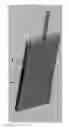
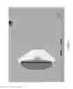
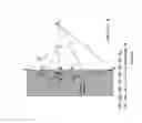
FIG. 1—illustrates the pressure variation in an old bat.
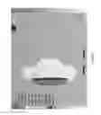
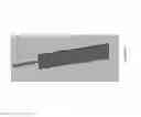
FIG. 2—illustrates the pressure variation in a new bat.
FIG. 3—illustrates the downward velocity v/s time graph.
FIG. 4—illustrates the downward velocity v/s time graph at a comfortable catching height.
FIG. 5—illustrates the calculation of the angle for chamfering indentation values and all the ranges for the angle.
FIG. 6—illustrates the calculation of the angle at the base of the bat.
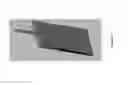
FIG. 7—illustrates the bat having edges chamfered to obtain a triangular shape.
FIG. 8—illustrates the calculation of the curve.
FIG. 9—illustrates the direction of impulse in a normal bat.
FIG. 10—illustrates the direction of impulse in the new bat.
DETAILED DESCRIPTION
The present disclosure provides a cricket bat especially having chamfers to negate the effects of swing bowling and reducing considerably the chances of getting caught behind. In accordance with the embodiments of the present disclosure the bat comprises of a handle and a blade. The blade further comprises a flat elongate planar striking face, an opposing rear face, 2 pair of chamfers, a pair of shoulders, a toe, a splice and a pair of sides spanning between the striking face and the opposing rear face. The blade extends from either sides of the handle i.e. from the shoulders till the toe.
In an embodiment of the present disclosure the striking face is a concave surface and the opposing rear face is a convex surface.
In a preferred embodiment of the present disclosure comprise a first longitudinal axis extending through the handle and the blade of the bat and a second perpendicular axis to the striking surface extending from the sides of the blade. The first longitudinal axis is perpendicular to the second perpendicular axis to the striking surface. The second perpendicular axis which divides the blade in two pair of sides also defines the 2 pairs of chamfers. In the present embodiment, a first pair of chamfers is located above the second perpendicular axis along the sides of the blade and extends till the shoulders thus making the striking surface slimmer towards the longitudinal axis and broader at the shoulder and a second pair of chamfers is located below the second perpendicular axis along the side of the blade and extends till the toe thus making the striking surface slimmer towards the longitudinal axis and broader at the toe. Both pair of chamfers are inclined towards the said striking face.
In another embodiment of the present disclosure comprise a first longitudinal axis extending through the handle and the blade of the bat and a second perpendicular axis to the striking surface extending from the thickest part of the sides of the blade. In yet another embodiment of the present disclosure the first pair of chamfers provides a downward forward component and the second pair of chamfers provides an upward forward component. The dotted arrows in FIG. 9 depict the impulse direction in case of a normal bat. The red region of the edge in FIG. 10 has a downward forward component (denoted by a solid downward arrow) while the blue region has an upward forward component (denoted by a solid upward arrow).
In yet another embodiment of the present disclosure the slope of the chamfers, which is determined by of one of the described axis, and the depth till which chamfering can be possible. This depth is an important constraint considered while developing the bat of the present disclosure. The greater the depth, the lesser the striking region, however more is the downward component. It is imperative to reduce the striking region only by that amount that it does not change the attacking game of the batsman. The maximum depth is 10 mm from both sides and the minimum depth should not be less than 5 mm.
In still another embodiment of the present disclosure the blade of a normal cricket bat is retro worked to the blade of the bat of the present disclosure.
In another embodiment of the present disclosure the bat is faster through the air while playing a shot due to the unique aerodynamic shape. The drag resistance on the bat reduces by 3-4%. In effect the bat speed while playing the shot increases by 1-2%
In yet another embodiment of the present disclosure the pressure at the striking face of the bat is lower in case of the bat of the present disclosure as compared to the normal bat. Less pressure implies that there is less resistance to the shot and thus less drag.
Comparison results of the software analysis are as shown in FIG. 1 and FIG. 2.
As seen in FIG. 1, the pressure region on the face of the bat is thicker as compared to the bat seen in FIG. 2. Also, a void is created at the rear of the bat while the same is absent in the case of the new designed bat.
Experimental Data:
This section describes a set of experiments in order to assess the performance of the two cricket bats i.e. the normal bat and the bat as disclosed in the present disclosure. The aim of this study is to compare performance characteristics with respect to three different shots between the normal cricket bat and the bat as disclosed in the present invention.
EXAMPLE 1
Forward Defence Velocity After Impact Comparison
Pre-processing parameters are as shown in Table 1.
| TABLE 1 |
| Pre-processing parameters for forward defence analysis |
| New Bat | With 3D Cut |
| Initial Distance of centre of ball from bottom | ¾ th of bat length |
| from bottom |
| Initial Distance of centre of ball from face | 78 | mm |
| Edge in Contact | 4 | mm |
| Edge contact is derived using simple kinematic equations and geometry |
| BOUNDARY CONDITION DETAILS |
| Bat is fixed |
| Initial Conditions for ball |
| X-Vel | 0 | m/sec |
| Y-Vel | 0 | m/sec |
| Z-Vel | −36 | m/sec |
| Wx | 0 | rad/sec |
| Wy | 0 | rad/sec |
| Wz | 0 | rad/sec |
| Gravity in Y direction | −9.8 | m/sec 2 |
| Total Time | 0.1 | sec |
| OTHER DETAILS |
| Ball is made up of a simple isotropic material having following properties |
| Density | 851 | Kg/m 3 |
| Young's Modulas | 1340 | Mpa |
| Poisson's ratio | 0.35 |
| The same model of ball is used in every simulation for comparison |
| Bat is made up of rigid surfaces by extracting surfaces from 3D cad |
| Fiction is considered as 0 |
The results of the analysis are shown in Table 2.
The 9th, 10th and 11th row represents the velocities just after the impact.
The changes in velocities due to the new bat can be seen in Table 3.
| TABLE 3 |
| Conclusion of the forward defence analysis |
| New bat | Effect | |
| X-component | Increases | Ball goes away from the keeper/slip |
| Y-component | Increases | Ball travels faster to the ground |
| Z-component | Decreases | Ball travels slower to the keeper/slips |
1. Cover Drive Velocity After Impact Comparison
The Pre Processing conditions for cover drive analysis are shown in Table 4
| TABLE 4 |
| Pre processinng conditions for cover drive analysis |
| GEOMETRY DETAILS |
| Ball Diamter | 72 | mm |
| Old Bat | Without 3D cut |
| New Bat | With 3D Cut |
| Initial Distance of centre of ball | ¾ th of batlength |
| from bottom | from bottom |
| Initial Distance of centre of ball from face | 136 | mm |
| Edge in Contact | 1 | mm |
| Edge contact is derived using simple kinematic equations and geometry |
| BOUNDARY CONDITION DETAILS |
| Bat is fixed |
| Initial Conditions for ball |
| X-Vel | 0 | m/sec |
| Y-Vel | 2.6 | m/sec |
| Z-Vel | −36 | m/sec |
| Wx | 0 | rad/sec |
| Wy | 0 | rad/sec |
| Wz | 0 | rad/sec |
| Gravity in Y direction | −9.8 | m/sec 2 |
| Total Time | 0.1 | sec |
| OTHER DETAILS |
| Ball is made up of a simple isotropic material having following properties |
| Density | 851 | Kg/m 3 |
| Young's Modulas | 1340 | Mpa |
| Poisson's ratio | 0.35 |
| The same model of ball is used in every simulation for comparison |
| Bat is made up of rigid surfaces by extracting surfaces from 3D cad |
| Dynamic friction Coefficient b/w | 0.4 | Used in every Simulation |
| ball and bat | ||
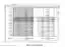
The results for the cover drive analysis can be seen in Table 5.
| TABLE 5 |
| Cover drive analysis results |
| Cover | Drive | ||||||
| Time [s] | X-Velocity | Y-Velocity | Z-Velocity | X-Velocity | Y-Velocity | Z-Velocity new [m/s] | |
| 1 | 1.18E−38 | 0 | 2.6 | −36 | 0 | 2.6 | −36 |
| 2 | 5.00E−04 | 0 | 2.5951 | −36 | 0 | 2.5951 | −36 |
| 3 | 1.00E−03 | 0 | 2.5902 | −36 | 0 | 2.5902 | −36 |
| 4 | 1.50E−03 | 0 | 2.5853 | −36 | 0 | 2.5853 | −36 |
| 5 | 2.00E−03 | 0 | 2.5804 | −36 | 0 | 2.5804 | −36 |
| 6 | 2.50E−03 | 0 | 2.5755 | −36 | 0 | 2.5755 | −36 |
| 7 | 3.00E−03 | 0 | 2.5706 | −36 | 0 | 2.5706 | −36 |
| 8 | 3.50E−03 | 0 | 2.5657 | −36 | 0 | 2.5657 | −36 |
| 9 | 4.00E−03 | 0 | 2.5608 | −36 | 0 | 2.5608 | −36 |
| 10 | 4.50E−03 | 0 | 2.5559 | −36 | 0 | 2.5559 | −36 |
| 11 | 5.00E−03 | 0 | 2.551 | −36 | 0 | 2.551 | −36 |
| 12 | 5.50E−03 | 0 | 2.5461 | −36 | 0 | 2.5461 | −36 |
| 13 | 6.00E−03 | 0 | 2.5412 | −36 | 0 | 2.5412 | −36 |
| 14 | 6.50E−03 | 0.7608 | 2.8172 | −25.874 | 3.5392 | 11.114 | −15.754 |
| 15 | 7.00E−03 | 2.7915 | 3.6505 | −22.783 | 4.274 | 7.5336 | −18.809 |
| 16 | 7.50E−03 | 2.6405 | 3.3401 | −22.267 | 4.2101 | 5.3516 | −21.236 |
| 17 | 8.00E−03 | 2.1016 | 4.0514 | −21.77 | 2.6261 | 4.5114 | −16.694 |
| 18 | 8.50E−03 | 2.9517 | 3.5215 | −23.056 | 3.8019 | 5.1238 | −22.382 |
| 19 | 9.00E−03 | 2.8927 | 3.4328 | −22.191 | 4.3766 | 4.823 | −21.81 |
| 20 | 9.50E−03 | 2.7377 | 3.5366 | −23.786 | 4.1218 | 4.3498 | −21.651 |
| 21 | 1.00E−02 | 2.1407 | 4.628 | −22.633 | 2.6716 | 4.6238 | −21.21 |
| Average | 2.590367 | 3.8658 | −22.87 | 3.723333 | 4.598867 | −21.557 |
| Velocity after | ||||||
| impact | ||||||
The 14th row represents the velocities just after impact. The changes in velocities due to the new bat can be seen in Table 6.
| TABLE 6 |
| Cover drive analysis conclusion |
| New bat | Effect | |
| X-component | Increases | Ball goes away from the keeper/slip |
| Y-component | Increases | Ball travels higher than the keeper/slip |
| Z-component | Decreases | Ball travels slower to the keeper/slips |
2. Square Cut velocity After Impact Comparison
The Pre Processing conditions for Square cut analysis are shown in Table 7.
| TABLE 7 |
| Pre processing conditions for square cut analysis |
| Initial Conditions |
| X-Vel | 0 | m/sec |
| Y-Vel | 2.78 | m/sec |
| Z-Vel | −36 | m/sec |
| Wx | −1.78 | rad/sec |
| Wy | 0 | rad/sec |
| Wz | 0 | rad/sec |
| Initial Distance of centre of | ¼ th of bat length |
| ball in X direction | from bottom |
| Initial Distance of edge of ball in y directin | 11 | mm |
| Initial Distance of centre of | 100 mm from the edge |
| ball in Z directin | and 136 mm from cent |
| Gravity in Y direction | −9.78 | m/sec 2 |
| Total Time | 0.008 | sec |
| Time at impact | 0.00278 | Sec |
| Dstance tavelled upward due to velocity | 7.69 | mm |
| Approx Final edge in contact | 2.31 | mm |
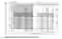
The results for the square cut analysis can be seen in Table 8.
| TABLE 8 |
| Square cut analysis results |
| Time [s] | X-Velocity | Y-Velocity | Z-Velocity | X-Velocity | Y-Velocity | Z-Velocity | |
| 1 | 1.18E−38 | 0 | 2.6339 | −36.026 | 0 | 2.9171 | −36.053 |
| 2 | 4.00E−04 | 3.70E−06 | 2.63 | −36.026 | 3.20E−06 | 2.9132 | −36.053 |
| 3 | 8.00E−04 | 2.67E−06 | 2.6261 | −36.026 | 2.62E−06 | 2.9093 | −36.053 |
| 4 | 1.20E−03 | 2.61E−06 | 2.6222 | −36.026 | 2.79E−06 | 2.9053 | −36.053 |
| 5 | 1.60E−03 | 2.86E−06 | 2.6182 | −36.026 | 2.76E−06 | 2.9014 | −36.053 |
| 6 | 2.00E−03 | 2.86E−06 | 2.6143 | −36.026 | 2.18E−06 | 2.8975 | −36.053 |
| 7 | 2.40E−03 | 3.02E−06 | 2.6104 | −36.026 | 3.28E−06 | 2.8936 | −36.053 |
| 8 | 2.80E−03 | 3.82E−06 | 2.6065 | −36.026 | 2.87E−06 | 2.8896 | −36.053 |
| 9 | 3.20E−03 | 3.43E−06 | 2.6025 | −36.026 | 3.31E−06 | 2.8857 | −36.053 |
| 10 | 3.60E−03 | 3.59E−06 | 2.5986 | −36.026 | 2.65E−06 | 2.8818 | −36.053 |
| 11 | 4.00E−03 | 2.4349 | 17.133 | −21.03 | 0.81551 | 13.199 | −24.863 |
| 12 | 4.40E−03 | 3.3863 | 17.294 | −22.141 | 1.8463 | 14.652 | −25.568 |
| 13 | 4.80E−03 | 2.0011 | 17.273 | −22.228 | 1.4446 | 14.722 | −25.372 |
| 14 | 5.20E−03 | 1.7839 | 16.852 | −20.784 | 1.4351 | 14.257 | −25.427 |
| 15 | 5.60E−03 | 1.5829 | 17.544 | −23.291 | 1.545 | 14.032 | −27.29 |
| 16 | 6.00E−03 | 1.9365 | 17.286 | −22.633 | 1.1991 | 14.279 | −25.92 |
| 17 | 6.40E−03 | 1.9087 | 16.923 | −23.104 | 1.2806 | 14.135 | −25.857 |
| 18 | 6.80E−03 | 1.4603 | 17.051 | −23.993 | 1.2292 | 13.495 | −26.743 |
| 19 | 7.20E−03 | 1.576 | 17.376 | −22.944 | 1.1002 | 14.697 | −24.89 |
| 20 | 7.60E−03 | 1.6196 | 17.102 | −22.82 | 0.86898 | 14.262 | −25.689 |
| 21 | 8.00E−03 | 1.7438 | 17.828 | −23.32 | 0.91899 | 14.035 | −26.883 |
| Average vel | −22.7258 | −25.9639 | |||
| after impact | |||||
The 11th row represents the velocities just after the impact. The changes in velocities due to the new bat can be seen in Table 9.
| TABLE 9 |
| Square cut analysis conclusion |
| New bat | Effect | |
| X-component | Decreases | Ball will go straight over the keeper |
| Y-component | Decreases | The time of flight of the ball reduces |
| Z-component | Increases | Ball travels faster decreasing time of flight |
Result and Calculations:
Overall result of the analysis for forward defence, cover drive and square cut is explained as follows.
In the case of forward defence, the range of the ball decreases and direction is a little away from slip. The ball falls short from landing into the hands of the slips in terms of its direction and reaches the ground earlier in terms of magnitude.
In the case of cover drive, the range of the ball increases and it goes away from the slip, when only the magnitude is considered. Thus when attempting a cover drive if a ball is edged, the ball travels away from the slip.
In the case of square cut, the range of the ball decreases and it goes away from 3rd man to just behind the keeper. Thus while attempting a square cut, the ball instead of landing near the third man, will fall short and will reach the ground between the third man and the keeper.
In all the above cases, standard fielding positions for a right hand batsman are considered.
All the above stated results are calculated in the following section. All the data used for the calculations is obtained from the respective tables. The calculations done below are just assuming ideal conditions. In real life scenario, there would be some deviations; however these deviations will be same for both the normal bat and the modified bat. Thus the inferences which are drawn from these calculations can be extended to real life scenarios.
Forward Defence
- Initial conditions (refer table 1)
| Old bat | New bat |
| s = 0.9 m | s = 0.9 m |
| u = 1.13 m/s | u = 1.9 m/s |
| g = 9.8 m/s2 | g = 9.8 m/s2 |
| s = utold + 0.5a (told)2 | 0.9 = 1.9tnew + (0.5)(9.8)(tnew)2 |
| 0.9 = 1.13told + (0.5)(9.8)(told)2 | tnew = 0.27 sec |
| Solving the above quadratic equation | |
| for t gives, | |
| told = 0.32 sec |
| Now calculating the range of the ball after it is hit, in case of both the bats: |
| x direction: | x direction: |
| sx-old = utold + 0.5a(told)2 | sx-new = utnew + 0.5a(tnew)2 |
| Where, u = 5.9, t = 0.32 sec, a = 0 | Where, u = 8.1, t = 0.27, a = 0 |
| Thus, | Thus, |
| sx-old = 1.88 m | sx-new = 2.18 m |
| z direction: | z direction: |
| sz-old = 27.9 × 0.32 = 8.37 | sz-new = 21.9 × 0.27 = 5.9 |
Cover Drive
- Initial conditions (refer table 4)
| Old bat: | New bat: | |
| s = 0.45 m | s = 0.45 m | |
| u = −2.8 m/s | u = −11.1 m/s | |
| g = 9.8 m/s2 | g = 9.8 m/s2 |
| Thus we get |
| told = 0.7 sec | tnew = 2.3 sec |
| Also the x direction |
| sx-old = 0.76 × 0.7 = 0.53 m | sx-new = 3.5 × 2.3 = 8.05 m |
| z direction |
| sz-old = 25.8 × 0.7 = 18 m | sz-new = 15.7 × 2.3 = 36.11 m | |
Square Cut
- Initial conditions (refer table 7)
| Old bat: | New bat: | |
| s = 0.135 m | s = 0.45 m | |
| u = −17.1 m/s | u = −13.2 m/s | |
| g = 9.8 m/s2 | g = 9.8 m/s2 | |
| told = 3.5 sec | tnew = 2.8 sec | |
| sx-old = 2.4 × 3.5 = 8.4 m | sx-new = 0.8 × 2.8 = 2.24 m | |
| sz-old = 21.03 × 3.5 = 73.6 m | sz-new = 24.8 × 2.8 = 69.4 m | |
EXAMPLE 2
Drag Analysis
Boundary parameters taken into consideration were inlet velocity 100kmph, outlet pressure 1 atmosphere, bat surface has no slip condition (velocity=0) and wall surface has free slip consideration.
The formula for drag coefficient is given below,
K=1/{10.5×(Air density)×(Air velocity)2}
When, the face of the bat is considered to be perpendicular to the air velocity
| Bat type | Drag Coefficient | |
| Old | K(484.24) | |
| new | K(466.79) | |
Thus drag reduction observed is 3.6%
EXAMPLE 3
Standard Conditions Considered for Testing
The standard playing parameters of an actual cricket pitch were considered for the testing, a few constraints were also chosen for the ball while the testing was done.
Parameters of the ball considered
Mass=160 gm, Radius=36 mm, Drag coefficient Cd=0.6
Thus drag force of the ball is given by
FD=0.5 pAv2Cd
Thus under the above conditions, comparative graphs of velocity v/s time of the ball to travel after hitting the bat and to reach the wicket keepers gloves were obtained as shown in FIG. 3 and FIG. 4. The FIG. 4 describes the reaction time the player gets to catch the ball when played with the bat of the present disclosure and the normal bat. The reaction time of the player is reduced substantially by 30% if the player intends to catch the ball comfortably at the same height as he can when the ball is hit with a normal bat.
Further to analyse, the average velocity of the ball after impact with bat is shown in table 10 below. It can be seen that the average velocity of the ball after impact with the new bat is greater as compared to a standard bat.
EXAMPLE 4
Variations of the Edges
In the present disclosure the edges can be chamfered in different variations but the maximum percentage variation in the length of the bat to mark the perpendicular axis is 20-80%. Thus with respect to the striking face of the bat, for 20% of the length of the bat (from top) the edges are going inwards and for the remaining 80% length the edges are going outwards towards the bottom. This ratio can be reversed depending upon the conditions and preferences.
The chamfering of the edges of the bat is basically a one to one mapping between the curve that is drawn on the striking face of the bat and the line of intersection of the edge and the opposing rear face. The indentation given to the bat at the perpendicular axis is 10mm maximum and the minimum is 5mm
Now that the angles are defined as in the FIG. 5 and FIG. 6,
- α1 (max)=5.19 degrees; α1 (min)=0.65 degrees
- α2 (max)=5.19 degrees; α1 (min)=0.65 degrees
- α3 (max)=178.92 degrees; α3 (min)=173.51 degrees
At the point where the perpendicular axis is drawn on the striking face of the bat, the edge of the bat makes and angle with the vertical plane. This angle is defined as α4.
α4(max)=21.8 degrees; α3(min)=7.1 degrees
Some non-limiting examples are mentioned herein.
-
- a) 60% top 40% bottom—If seen from a front view, both the edges travel inwards for the 60% of the bat from the top and start going outward for the remaining 40% towards the bottom.
- a. It is observed that, most of the edges are hit by the top 60% of the edge of a bat, thus a greater length of the bat has the modified edge. Also, the region where the thickness of the bat is maximum, max edge surface is provided, as this the region where the transition of the edge starts (from going inwards to outwards-top to bottom).
- b) 40% top 60% bottom—if seen from a front view, both the edges travel inwards for the 40% of the bat from the top and start going outwards for the remaining 60% towards the bottom.
- a. In this design, the upper 40% edge are coming inwards thus the upper portion of the new developed edges have downward component slightly greater than in variation 1, thus it is observed that in this variation of the edges, the ball experiences a more downward force as compared to that in variation 1.
- c) If seen from a front view, left edge—60% top 40% bottom, right edge 40%top 60% bottom—Considering a right hand batsman, the outside edge for him should be 60% inwards from top and the rest is designed accordingly. This design has an advantage that the bat is not thin in a particular region if observed from a front view. As observed in the above two cases, the point where the edges get divided is the thinnest point of that bat (in a front view), this is not the case in this variation which is a skewed distribution of the edges.
- d) Triangular edges—the edges of the bat are divided into two equal parts and triangular faces for the edges are created as seen in FIG. 7. The advantage of such type of a variation is the improved backswing aerodynamics. It is observed that, after playing a shot, the follow through of the bat shows lesser resistance through air, thus adding perfection to a shot. Also, the slope of forward component in this type of edge is increased thus the ball would get an increased forward force (when compared to other variations), thus reducing its range.
- a) 60% top 40% bottom—If seen from a front view, both the edges travel inwards for the 60% of the bat from the top and start going outward for the remaining 40% towards the bottom.
EXAMPLE 5
Field Trials
Field testing of the both the normal and the bat of the present disclosure was done in a net session, approximately 200 balls were faced by each bat and a standard bowling machine was used for the deliveries. It was observed that when a ball was edged, a good amount of energy was taken off from it, thus making it fall early to the ground. All the shots played were defensive strokes as it is generally observed that most of the edges are hit while playing such kind of a shot.
It was also observed that the number of balls travelling towards the third slip and gully region was greater in the case of the bat of the present disclosure.
EXAMPLE 6
Calculation of the Curve
With reference to FIG. 8, In ΔAMB,
tan θ=E01/d 1
- In ΔBME,
tan α=E02/d 2
- Also, ΔABC, ΔBDE are isosceles triangles with AC=BC and BD=DE
- In ΔPBC,
cos θ=EL2/2r1 3
- In ΔBDG
cos α=EL2/2r2 4
- By Pythagoras Theorem,
- In ΔAMB,
EL1={(E01)2+(d)2}(1/2) 5
- In ΔBME,
EL2={(E02)2+(d)2}(1/2) 6
- Calculation for r1
- We know,
tan2 θ=(1×cos2θ)/cos2θ 7
- Substituting eq. 7 in eq. 1, we get
(E01)2/(d)2=(1−cos2 θ)/cos2 θ
- By Componendo,
{(E01)2+(d)2}/(d)2=1/cos2 θ
Substituting the value of cos θ from eq. 3, we get,
(d)2/{(E01)2+(d)2}=(EL1)2/4(r1)2
Substituting the value of E2L1 (eq.5) in the above equation and solving for r1 gives,
r1={(E01)2+(d)2}/4d2
Similarly, using equations equations 2,4, 6 and 7, we can derive the value of r2.
Calculating the values of r1 and r2, will give us the radius of the arcs which can then be used to sketch a curve on the face of the bat. Thus the edges of the bat are now to be chamfered off along this curve obtained.
TECHNICAL ADVANCEMENTS AND ECONOMICAL SIGNIFICANCE
The technical advancements offered by the present disclosure include the realization of:
-
- a cricket bat which considerably reduces the chances of a batsman's edge flying to a fielder behind the stumps.
- a simple and economic aerodynamic design to improve the bat speed and optimize the weight of the bat.
- a flexible design to modify the bat which does not require the batsman to alter his style of playing or using the bat.
- to retro work an existing normal bat as the bat of the present disclosure.
- A cricket bat which can be used in all formats of a cricket game.
Throughout this specification the word “comprise”, or variations such as “comprises” or “comprising”, will be understood to imply the inclusion of a stated element, integer or step, or group of elements, integers or steps, but not the exclusion of any other element, integer or step, or group of elements, integers or steps.
Any discussion of documents, acts, materials, devices, articles or the like that has been included in this specification is solely for the purpose of providing a context for the disclosure. It is not to be taken as an admission that any or all of these matters form part of the prior art base or were common general knowledge in the field relevant to the disclosure as it existed anywhere before the priority date of this application.
The foregoing description of the specific embodiments will so fully reveal the general nature of the embodiments herein that others can, by applying current knowledge, readily modify and/or adapt for various applications such specific embodiments without departing from the generic concept, and, therefore, such adaptations and modifications should and are intended to be comprehended within the meaning and range of equivalents of the disclosed embodiments. It is to be understood that the phraseology or terminology employed herein is for the purpose of description and not of limitation. Therefore, while the embodiments herein have been described in terms of preferred embodiments, those skilled in the art will recognize that the embodiments herein can be practiced with modification within the spirit and scope of the embodiments as described herein.
Claims
What is claimed is:1. A cricket bat comprising:
a) a blade extending from a pair of shoulders from either side of a handle at a top operative end to a toe at a bottom operative end, a striking face, an opposing rear face and a pair of sides spanning between said striking face and said opposing rear face; said striking face formed by a flat elongate planar surface, said a striking face defined by i.) a first longitudinal axis, ii.) a second perpendicular axis perpendicular to the said first longitudinal axis extending across the said striking face from one side to the other side of said striking face, said pair of sides defining a first pair of chamfers extending from the ends of said second perpendicular axis upto the said shoulders such that the said striking face is slimmer at the said longitudinal axis and broader at the said shoulders and a second pair of chamfers extending from the ends of second perpendicular axis upto the toe such that the said striking face is slimmer at the said longitudinal axis and broader at the said toe, both the pair of chamfers being inclined towards the said striking face.
2. The cricket bat as claimed in claim 1, wherein:
the first pair of chamfers provide a downward forward component component; and
the second pair of chamfers provide a upward forward component.
3. The cricket bat as claimed in claim 1, wherein the surface of said striking face is concave.
4. The cricket bat as claimed in claim 1, wherein the surface of said opposing rear face is convex.
5. A cricket bat where the blade is retro worked as claimed in claim 1.
Images & Drawings included:
Sources:
- United States Patent and Trademark Office - verify current appl. status at the USPTO↗
Recent applications in this class:
- » 20230381609 2023-11-30
SYSTEM AND METHOD OF COMPRESSING AND SHAPING A BARREL OF A WOODEN BASEBALL BAT - » 20220296974 2022-09-22
HYBRID BASEBALL BAT AND CONSTRUCTION METHODS - » 20200346086 2020-11-05
Hybrid baseball bat and construction methods - » 20190126112 2019-05-02
Wooden baseball bat - » 20190070471 2019-03-07
CELLULOSIC AND LIGNOCELLULOSIC STRUCTURAL MATERIALS AND METHODS AND SYSTEMS FOR MANUFACTURING SUCH MATERIALS - » 20120302383 2012-11-29
Bat Safety System - » 20120082296 2012-04-05
Cellulosic and lignocellulosic structural materials and methods and systems for manufacturing such materials - » 20120074337 2012-03-29
Cellulosic and lignocellulosic structural materials and methods and systems for manufacturing such materials - » 20120065008 2012-03-15
Baseball bat structure and method for making the same - » 20110312452 2011-12-22
Bat having fiber-fused core section and method of manufacturing the same