Picking ladder cart
US20160160561A1
2016-06-09
14/957,960
2015-12-03
✅ Patent granted
US 9,573,609 B2
2017-02-21
-
-
Katherine Mitchell | Marcus Menezes
Ming Chow | Sinorica, LLC
2035-12-03
Abstract:
A picking ladder cart with a synchronized brake is provided, which includes a frame, a plurality of wheels, a ladder, and a stopper. The wheels are installed at a bottom of the frame. The ladder is pivotally connected to a side of the frame, wherein the ladder is pivotally movable between a first position and a second position. The ladder includes two side rails and a plurality of steps which are connected between the two side rails. The stopper has a first end and a second end, wherein the first end is connected to the bottom of the frame, and the second end is close to the ladder. When the ladder is moved to the second position, one of the plurality of steps which is arranged at the lowest position among the steps abuts against the second end of the stopper, which makes the stopper contact one of the wheels. Whereby, when an operator steps on the ladder of the picking ladder cart, the lowest step drives the stopper to abut against and stop the wheels, which increases the working efficiency.
Assignee:
- ROMP ENTERPRISE CO., LTD. 4 🇹🇼 Taichung, Taiwan
Applicant:
Interested in similar patents?
Get notified when new applications in this technology area are published.
Classification:
B62B3/022 » CPC main
Hand carts having more than one axis carrying transport wheels; Steering devices therefor; Equipment therefor involving parts being adjustable, collapsible, attachable, detachable or convertible folding down the body to the wheel carriage or by retracting projecting parts
B62B3/02 IPC
Hand carts having more than one axis carrying transport wheels; Steering devices therefor; Equipment therefor involving parts being adjustable, collapsible, attachable, detachable or convertible
E06C7/02 » CPC further
Component parts, supporting parts, or accessories Extending means
E06C7/18 IPC
Component parts, supporting parts, or accessories Devices for preventing persons from falling
E06C1/39 » CPC further
Ladders in general with rigid longitudinal member or members; Special constructions of ladders, e.g. ladders with more or less than two longitudinal members, ladders with movable rungs or other treads, longitudinally-foldable ladders Ladders having platforms; Ladders changeable into platforms
E06C7/16 » CPC further
Component parts, supporting parts, or accessories Platforms on, or for use on, ladders, e.g. liftable or lowerable platforms
E06C1/397 » CPC further
Ladders in general with rigid longitudinal member or members; Special constructions of ladders, e.g. ladders with more or less than two longitudinal members, ladders with movable rungs or other treads, longitudinally-foldable ladders characterised by having wheels, rollers, or runners
E06C5/02 » CPC main
Ladders characterised by being mounted on undercarriages or vehicles Securing ladders on vehicles with rigid longitudinal members
E06C7/182 » CPC further
Component parts, supporting parts, or accessories; Devices for preventing persons from falling; Additional gripping devices, e.g. handrails situated at the top of the ladder
B62B3/10 » CPC further
Hand carts having more than one axis carrying transport wheels; Steering devices therefor; Equipment therefor characterised by supports specially adapted to objects of definite shape
Description
BACKGROUND OF THE INVENTION
1. Technical Field
The present invention relates generally to a conveying appliance used for warehousing, and more particularly to a picking ladder cart with a synchronized brake.
2. Description of Related Art
In storage spaces such as warehouses, materials and goods are stocked on the shelves in different categories. For the convenience of conveying, picking ladder carts are commonly used in moving the materials and goods to and from the shelves.
A conventional picking ladder cart includes at least one brake installed on wheels. An operator has to depress the brake pedal to stop the wheel before stepping on a ladder of the picking ladder cart, and has to release the brake to make the wheel able to roll before pushing and moving the picking ladder cart. Although such steps can ensure the safety during operation, it requires more operational procedures, and therefore reduces the working efficiency.
In light of this, the applicant of the present invention has developed a picking ladder cart with a brake structure which enables operators to conveniently brake the cart. In more details, Taiwan patent M483214 discloses the brake structure of the picking ladder cart; said brake structure includes an interlocking structure and a stopper to brake the picking ladder cart as a ladder thereof is unfold. The steps of depressing and releasing the brake are omitted with such design, which increases the working efficiency.
However, the applicant still devotes himself to develop a cost-effective picking ladder cart which provides the same function.
BRIEF SUMMARY OF THE INVENTION
In view of the above, the primary objective of the present invention is to provide a picking ladder cart with a synchronized brake, which is not only able to be easily braked but also cost-effective.
The present invention provides a picking ladder cart with a synchronized brake, which includes a frame, a plurality of wheels, a ladder, and a stopper. The plurality of wheels are installed at a bottom of the frame, which makes the picking ladder cart movable on a flat surface. The ladder is pivotally connected to a side of the frame, wherein the ladder is pivotally movable between a first position and a second position. The ladder includes two side rails and a plurality of steps which are connected between the two side rails. The two side rails are close to the frame when the ladder is moved to the first position, and are moved away from the frame when the ladder is moved to the second position. The stopper is provided at the bottom of the frame, which has a first end and a second end, wherein the first end is connected to the bottom of the frame, and the second end is close to the ladder. Whereby, when the ladder is moved to the second position, one of the plurality of steps which is arranged at the lowest position among the steps abuts against the second end of the stopper, which makes a middle part of the stopper contact one of the wheels.
Whereby, when an operator steps on the ladder of the picking ladder cart, the lowest step drives the stopper to abut against and stop the wheels, which increases the working efficiency.
BRIEF DESCRIPTION OF THE SEVERAL VIEWS OF THE DRAWINGS
The present invention will be best understood by referring to the following detailed description of some illustrative embodiments in conjunction with the accompanying drawings, in which
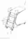
FIG. 1 is a perspective view of a preferred embodiment of the present invention, showing the picking ladder cart with a synchronized brake;
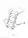
FIG. 2 is a partial lateral view of the preferred embodiment, showing the stopper having no contact with the wheel when the ladder is moved to the first position;
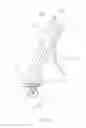
FIG. 3 is a partial lateral view of the preferred embodiment, showing the lowest step drives the stopper to abut against the wheel when the ladder is moved to the second position; and
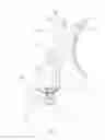
FIG. 4 is a partial enlarged view of the preferred embodiment, showing the first end of the stopper pivotally connected to the bottom of the frame.
DETAILED DESCRIPTION OF THE INVENTION
As shown in FIG. 1 and FIG. 2, a picking ladder cart 1 of the preferred embodiment of the present invention includes a frame 10, a plurality of wheels 12, a ladder 20, and a stopper 30. The plurality of wheels 12 are installed at a bottom of the frame, which makes the picking ladder cart 1 movable on a flat surface F.
The ladder 20 is pivotally connected to a side of the frame 10, and is pivotally movable between a first position P1 and a second position P2. The ladder 20 includes two side rails 22 and a plurality of steps, wherein the steps are arranged with intervals formed between two of the steps, and are connected between the two side rails 22. In the preferred embodiment, the steps includes two upper steps 24 and the lowest step 26, wherein each of the two upper steps 24 has a first pivoted end 241, a second pivoted end 242, and an upper surface 24a. The first pivoted end 241 is pivotally connected to the side of the frame 10, and the second pivoted end 242 is pivotally connected to one of the side rails 22. The two side rails 22 are connected to the frame 10 through the upper steps 24.
The lowest step 26 is fixed to the two side rails 22, and has an upper surface 26a for an operator to step on. As illustrated in FIG. 2, the two side rails 22 are close to the frame 10, and an included angle 0 is formed between an extension direction of the upper surface 24a of each of the upper steps 24 and the flat surface F. In other words, the upper surface 24a is nonparallel to the flat surface F in this state, where the ladder 20 is in the first position P1.
When the operator steps on the upper surface 26a of the lowest step 26, the two side rails 22 are moved down and away from the frame 10, and the two upper steps 24 are moved to a horizontal state as shown in FIG. 3. In this state, the upper surface 24a of each of the upper steps 24 is substantially parallel to the flat surface F, where the ladder 20 is in the second position P2. In this way, the operator can step on the two upper steps 24.
Additionally, the stopper 30 in the preferred embodiment is a curved rigid sheet, and has a first end 301 and a second end 302. The stopper 30 is provided between the bottom of the frame 10 and one of the wheels 12, wherein the first end 301 is connected to the bottom of the frame 10 through a spring seat 40. The second end 302 is exposed outside the orthogonal projection area of the frame 10, and is close to the ladder 20.
In more details, the spring seat 40 depicted in FIG. 4 includes two shaft tubes 42, a sleeve 44, a shaft 46, and a flexible member, wherein the flexible member in the preferred embodiment is a torsion spring 48. The two shaft tubes 42 are fixed to the bottom of the frame, and are separated from each other. The sleeve 44 is provided between the two shaft tubes 42, and the shaft 46 passes through the two shaft tubes 42 and the sleeve. With such design, the sleeve 44 is rotatably installed at the bottom of the frame. The first end 301 of the stopper 30 is welded to the outer surface of the sleeve 44, and the stopper 30 is therefore pivotable on the shaft 46.
Two ends of the torsion spring 48 are twisted round the two shaft tubes 42 respectively to be supported for providing an upward force to the stopper through the middle section of the torsion spring 48. When the ladder 20 is moved to the first position
P1 shown in FIG. 2, the stopper 30 has no contact with the lowest step 26 and the wheels 12.
On the other hand, when the operator would like to climb on the ladder 20, he or she has to step on and depress the lowest step 26 to drive the ladder 20 to move to the second position P2, which is illustrated in FIG. 3. In this state, the lowest step 26 abuts against the second end 302 of the stopper 30, and the wheel 12 is accordingly abutted by the middle section of the stopper 30, which stops the picking ladder cart 1.
It must be pointed out that the embodiment described above is only a preferred embodiment of the present invention. All equivalent structures which employ the concepts disclosed in this specification and the appended claims should fall within the scope of the present invention.
Claims
What is claimed is:1. A picking ladder cart, comprising:
a frame;
a plurality of wheels installed at a bottom of the frame, which makes the picking ladder cart movable on a flat surface;
a ladder pivotally connected to a side of the frame, wherein the ladder is pivotally movable between a first position and a second position, and comprises two side rails and a plurality of steps which are connected between the two side rails; the two side rails are close to the frame when the ladder is moved to the first position; the two side rails are moved away from the frame when the ladder is moved to the second position; and
a stopper provided at the bottom of the frame, which has a first end and a second end, wherein the first end is connected to the bottom of the frame, and the second end is close to the ladder;
whereby, when the ladder is moved to the second position, one of the plurality of steps which is arranged at the lowest position among the steps abuts against the second end of the stopper, which makes a middle part of the stopper contact one of the wheels.
2. The picking ladder cart of claim 1, wherein at least one of the steps has a first pivoted end, a second pivoted end, and an upper surface ; the first pivoted end is pivotally connected to the side of the frame, and the second pivoted end is pivotally connected to one of the side rails; when the ladder is moved to the first position, an included angle is formed between an extension direction of the upper surface and the flat surface; when the ladder is moved to the second position, the upper surface is substantially parallel to the flat surface.
3. The picking ladder cart of claim 1, wherein the lowest step is fixed to the two side rails, and has an upper surface; when the ladder is moved to the second position, the upper surface is substantially parallel to the flat surface.
4. The picking ladder cart of claim 1, further comprising a flexible member provide at the bottom of the frame, which gives an upward force to the stopper, wherein when the ladder is moved to the first position, the stopper has no contact with the lowest step and the wheels.
5. The picking ladder cart of claim 4, further comprising two shaft tubes, a sleeve, and a shaft, wherein the two shaft tubes are fixed to the bottom of the frame, and are separated from each other; the sleeve is provided between the two shaft tubes, and the shaft passes through the two shaft tubes and the sleeve; the stopper is fixed to an outer surface of the sleeve with the first end thereof, and is pivotable on the shaft; the flexible member comprises a torsion spring, which is supported by the two shaft tubes, and provides the upward force to the stopper.
Images & Drawings included:
Sources:
- United States Patent and Trademark Office - verify current appl. status at the USPTO↗
Similar patent applications:
- » 20160319600
Foldable picking ladder cart
Recent applications in this class:
- » 20230383602 2023-11-30
LADDER/RAMP - » 20220136326 2022-05-05
Vehicle ladder - » 20150252618 2015-09-10
Door mounted ladder for cargo vans - » 20140326537 2014-11-06
Mobile access unit and cage - » 20140158465 2014-06-12
Ladder assembly for a work vehicle - » 20130319794 2013-12-05
Adjustable ladder support mechanism - » 20120240379 2012-09-27
VEHICLE LADDER MOUNTING SYSTEM - » 20110127111 2011-06-02
Tracking gate for extended gangway - » 20100122871 2010-05-20
Tractor Tire-Mountable Folding Step Ladder - » 20100096215 2010-04-22
LADDER ASSEMBLY AND ASSOCIATED METHODS OF USE
Recent applications for this Assignee:
- » 20160319600 2016-11-03
Foldable picking ladder cart - » 20110101289 2011-05-05
FLOOR TILE PUSHER - » 20110067354 2011-03-24
TILE PUSHER FOR FLOOR TILES