High straightness arrow and method of manufacture
US20160161227A1
2016-06-09
14/605,939
2015-01-26
✅ Patent granted
US 10,161,727 B2
2018-12-25
-
-
Seyed Masoud Malekzadeh
Joseph Sherinsky
2037-03-20
Abstract:
The high straightness arrow in the present invention is designed to improve the straightness of the archery arrow by adopting new manufacturing technique and method. Chamber and post are made of dissimilar metals and the chamber includes a wall that creates an external housing and defines an internal airspace. Once the post with shaft is positioned through chamber, nuts are tightened securely, forming an assembly, to straighten post. Due to the different coefficients of thermal expansion of chamber and post, when they are heated simultaneously, the chamber expands more than the post, creating a natural tension along post which results in a near perfectly straight shaft. As the assembly cools, the post and chamber return to their original length, yet the shaft retains its straightened form and thus this manufacturing process yields an arrow shaft that is straighter than shafts made of the same materials but with a traditional manufacturing technique.
Assignee:
- ALDILA GOLF CORP. 10 🇺🇸 Poway, CA, United States
- Aldila Golf Corporation 6 🇺🇸 Carlsbad, CA, United States
Applicant:
Interested in similar patents?
Get notified when new applications in this technology area are published.
Classification:
F42B6/04 » CPC main
Projectiles or missiles specially adapted for projection without use of explosive or combustible propellant charge, e.g. for blow guns, bows or crossbows, hand-held spring or air guns; Arrows; Crossbow bolts; Harpoons for hand-held spring or air guns Archery arrows
B29C57/00 » CPC further
Shaping of tube ends, e.g. flanging, belling or closing; Apparatus therefor, e.g. collapsible mandrels
B29C70/56 » CPC further
Shaping composites, i.e. plastics material comprising reinforcements, fillers or preformed parts, e.g. inserts comprising reinforcements only, e.g. self-reinforcing plastics; Shaping operations therefor; Component parts, details or accessories; Auxiliary operations, e.g. feeding or storage of prepregs or SMC after impregnation or during ageing Tensioning reinforcements before or during shaping
F41B5/148 » CPC further
Bows; Crossbows; Details of bows; Accessories for arc shooting; Accessories for arc or bow shooting Accessories and tools for bow shooting not otherwise provided for
B29C33/485 » CPC further
Moulds or cores; Details thereof or accessories therefor with means for, or specially constructed to facilitate, the removal of articles, e.g. of undercut articles with means for collapsing or disassembling cores or mandrels
B29C33/505 » CPC further
Moulds or cores; Details thereof or accessories therefor with means for, or specially constructed to facilitate, the removal of articles, e.g. of undercut articles with means for collapsing or disassembling elastic or flexible cores or mandrels, e.g. inflatable
B29C35/0227 » CPC further
Heating, cooling or curing, e.g. crosslinking or vulcanising; Apparatus therefor; Heating or curing, e.g. crosslinking or vulcanizing during moulding, e.g. in a mould using pressure vessels, e.g. autoclaves, vulcanising pans
B29C35/0238 » CPC further
Heating, cooling or curing, e.g. crosslinking or vulcanising; Apparatus therefor; Heating or curing, e.g. crosslinking or vulcanizing during moulding, e.g. in a mould using pressure vessels, e.g. autoclaves, vulcanising pans Presses provided with pressure vessels, e.g. steam chambers
B29C53/566 » CPC further
Shaping by bending, folding, twisting, straightening or flattening; Apparatus therefor; Winding and joining, e.g. winding spirally for making tubular articles followed by compression
B29C53/824 » CPC further
Shaping by bending, folding, twisting, straightening or flattening; Apparatus therefor; Component parts, details or accessories; Auxiliary operations; Cores or mandrels; Mandrels especially adapted for winding and joining collapsible, e.g. elastic or inflatable; with removable parts, e.g. for regular shaped, straight tubular articles
B29C57/005 » CPC further
Shaping of tube ends, e.g. flanging, belling or closing; Apparatus therefor, e.g. collapsible mandrels the end of an internal lining
B29C66/00 » CPC further
General aspects of processes or apparatus for joining preformed parts
B29C70/34 » CPC further
Shaping composites, i.e. plastics material comprising reinforcements, fillers or preformed parts, e.g. inserts comprising reinforcements only, e.g. self-reinforcing plastics; Shaping operations therefor; Shaping by lay-up, i.e. applying fibres, tape or broadsheet on a mould, former or core; Shaping by spray-up, i.e. spraying of fibres on a mould, former or core and shaping or impregnating by compression, i.e. combined with compressing after the lay-up operation
B29C70/342 » CPC further
Shaping composites, i.e. plastics material comprising reinforcements, fillers or preformed parts, e.g. inserts comprising reinforcements only, e.g. self-reinforcing plastics; Shaping operations therefor; Shaping by lay-up, i.e. applying fibres, tape or broadsheet on a mould, former or core; Shaping by spray-up, i.e. spraying of fibres on a mould, former or core and shaping or impregnating by compression, i.e. combined with compressing after the lay-up operation using isostatic pressure
B29C70/42 » CPC further
Shaping composites, i.e. plastics material comprising reinforcements, fillers or preformed parts, e.g. inserts comprising reinforcements only, e.g. self-reinforcing plastics; Shaping operations therefor; Shaping or impregnating by compression not applied for producing articles of definite length, i.e. discrete articles
B29C70/44 » CPC further
Shaping composites, i.e. plastics material comprising reinforcements, fillers or preformed parts, e.g. inserts comprising reinforcements only, e.g. self-reinforcing plastics; Shaping operations therefor; Shaping or impregnating by compression not applied for producing articles of definite length, i.e. discrete articles using isostatic pressure, e.g. pressure difference-moulding, vacuum bag-moulding, autoclave-moulding or expanding rubber-moulding
B29C70/446 » CPC further
Shaping composites, i.e. plastics material comprising reinforcements, fillers or preformed parts, e.g. inserts comprising reinforcements only, e.g. self-reinforcing plastics; Shaping operations therefor; Shaping or impregnating by compression not applied for producing articles of definite length, i.e. discrete articles using isostatic pressure, e.g. pressure difference-moulding, vacuum bag-moulding, autoclave-moulding or expanding rubber-moulding Moulding structures having an axis of symmetry or at least one channel, e.g. tubular structures, frames
B29L2023/22 » CPC further
Tubular articles Tubes or pipes, i.e. rigid
B29L2031/52 » CPC further
Other particular articles Sports equipment ; Games; Articles for amusement ; Toys
F42B6/02 » CPC further
Projectiles or missiles specially adapted for projection without use of explosive or combustible propellant charge, e.g. for blow guns, bows or crossbows, hand-held spring or air guns Arrows; Crossbow bolts; Harpoons for hand-held spring or air guns
F42B6/06 » CPC further
Projectiles or missiles specially adapted for projection without use of explosive or combustible propellant charge, e.g. for blow guns, bows or crossbows, hand-held spring or air guns; Arrows; Crossbow bolts; Harpoons for hand-held spring or air guns; Archery arrows Tail ends, e.g. nocks, fletching
F42B6/08 » CPC further
Projectiles or missiles specially adapted for projection without use of explosive or combustible propellant charge, e.g. for blow guns, bows or crossbows, hand-held spring or air guns; Arrows; Crossbow bolts; Harpoons for hand-held spring or air guns Arrow heads; Harpoon heads
F42B35/02 » CPC further
Gauging, sorting, trimming or shortening cartridges or missiles
F41B5/14 IPC
Bows; Crossbows Details of bows; Accessories for arc shooting
B29C53/82 IPC
Shaping by bending, folding, twisting, straightening or flattening; Apparatus therefor; Component parts, details or accessories; Auxiliary operations Cores or mandrels
B29C33/48 IPC
Moulds or cores; Details thereof or accessories therefor with means for, or specially constructed to facilitate, the removal of articles, e.g. of undercut articles with means for collapsing or disassembling
B29C65/00 IPC
Joining of preformed parts ; Apparatus therefor
B29C70/06 » CPC further
Shaping composites, i.e. plastics material comprising reinforcements, fillers or preformed parts, e.g. inserts comprising reinforcements only, e.g. self-reinforcing plastics Fibrous reinforcements only
B29C57/02 » CPC further
Shaping of tube ends, e.g. flanging, belling or closing; Apparatus therefor, e.g. collapsible mandrels Belling or enlarging, e.g. combined with forming a groove
B29C35/02 IPC
Heating, cooling or curing, e.g. crosslinking or vulcanising; Apparatus therefor Heating or curing, e.g. crosslinking or vulcanizing during moulding, e.g. in a mould
B29C53/56 » CPC further
Shaping by bending, folding, twisting, straightening or flattening; Apparatus therefor Winding and joining, e.g. winding spirally
B29C33/50 IPC
Moulds or cores; Details thereof or accessories therefor with means for, or specially constructed to facilitate, the removal of articles, e.g. of undercut articles with means for collapsing or disassembling elastic or flexible
B29C57/12 » CPC further
Shaping of tube ends, e.g. flanging, belling or closing; Apparatus therefor, e.g. collapsible mandrels Rim rolling
Description
CROSS REFERENCE TO RELATED APPLICATION
This application is a divisional of, and claims the benefit of priority to, U.S. Utility patent application Ser. No. 13/298,287 filed Nov. 16, 2011, entitled “High Straightness Arrow and Method of Manufacture,” and currently co-pending, which claims priority to and the benefit of U.S. Provisional Patent Application Ser. No. 61/413,983, filed on Nov. 16, 2010, entitled “High Straightness Arrow and Method of Manufacture.”
BACKGROUND OF THE INVENTION
1. Field of the Invention
The present invention relates generally to archery arrows, and more specifically to techniques for improving the straightness of the arrow and method of manufacture for the high straightness arrow. The present invention is more particularly, though not exclusively, useful as a manufacturing technique which provides for more consistent straightness to the arrows.
2. Description of the Related Art
In the archery industry, there is a consistent drive towards manufacturing arrows having improved straightness. Specifically, an arrow's flight path is determined in large part by the flexibility and straightness of the arrow shaft. While some natural oscillations are expected in a carbon fiber shaft, the overall, steady state straightness is highly coveted by archers as it improves the accuracy of the arrow shot.
In light of this consistent pursuit of arrow straightness, a high straightness arrow and method of manufacture have been developed. The high straightness arrow is manufactured from carbon fiber materials generally known and used in the archery industry. Arrows manufactured using the technique of the present invention are consistently more straight than arrows made using the same materials but with a traditional manufacturing technique.
SUMMARY OF THE INVENTION
The high straightness arrow in the present invention is designed to improve the straightness of the archery arrow by adopting new manufacturing technique and method of using carbon fiber materials.
In a preferred embodiment, chamber and post are made of dissimilar metals and the chamber includes a wall that creates an external housing and defines an internal airspace. The post wrapped with a carbon fiber shaft may be inserted into the chamber and post may be threaded on its ends that extend outside chamber. Once post with shaft is positioned through chamber, nuts are tightened securely, forming an assembly, to straighten post. Due to the greater coefficient of thermal expansion of chamber than that of post, when they are heated simultaneously, the chamber length expands more than the length of the post.
At the end of the heating cycle, a difference in length of chamber and post creates a natural tension along post which results in a near perfectly straight shaft. As the assembly cools, the post and chamber return to their original length, yet the shaft retains its straightened form and thus this manufacturing process yields an arrow shaft that is straighter than shafts made of the same materials but with a traditional manufacturing technique.
BRIEF DESCRIPTION OF THE DRAWINGS
The nature, objects, and advantages of the present invention will become more apparent to those skilled in the art after considering the following detailed description in connection with the accompanying drawings, in which like reference numerals designate like parts throughout, and wherein:
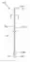
FIG. 1 is a diagrammatic view of an arrow in the present invention, with an illustration of lateral flexure when it is shot;
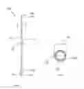
FIG. 2 is a cross-sectional view taken along lines 2-2 of FIG. 1;
FIG. 3 is a diagrammatic view of an arrow equipped within a chamber used to manufacture the high straightness arrow and method of manufacture in the present invention;
FIG. 4 is a diagrammatic view of a chamber loaded with post, shaft and nuts illustrating the expansion of the chamber when heated; and
FIG. 5 is a graphical representation of the correspondingly expanded lengths of the chamber and post in the present invention.
DETAILED DESCRIPTION OF THE INVENTION
Referring to FIG. 1, an arrow is shown and generally designated 100. Arrow 100 includes a shaft 102 with a tip end 104 having equipped with a point 106, and fletching 108 adjacent nock end 110 equipped with a nock 112. Arrow 100 often is manufactured with an inherent, yet unwanted, curvature shown by dashed lines 102′. This curvature creates a flight path that is not as straight as a perfectly straight arrow as the curvature results in a flight that is not axial to the arrow shaft 102. Specifically, the arrow shaft 102 bends along its length so as to deflect a distance 114. As a result of the non-linear flight, the target is often missed.
FIG. 2 is a cross-sectional view of the arrow 100 as taken along lines 2-2 of FIG. 1 which illustrates a shaft 102 having a diameter 116, a wall thickness 118, and defines an internal bore 120. These dimensions can vary depending on the type of arrow being manufactured, and can be increased or decreased depending on the materials used in the shaft, as well as the style of arrow being manufactured.
The chamber used to manufacture the high straightness arrow and method of manufacture is shown in FIG. 3 with a portion cut away for clarity, and generally designated 150. Chamber 150 includes a wall 152 that creates an external housing 154 and defines an internal airspace 156. Wall 152 is formed with a pair of holes 158 through which a post 160 can be inserted such that post 160 passes longitudinally through the internal chamber 156. It is appreciated that chamber 150 may be made such that the post 160 wrapped with a carbon fiber shaft 102 may be inserted. For instance, chamber 150 may have multiple pieces, a removable cover, or the holes 158 are sized to pass post 162 with shaft 102 through the length of the chamber 150. Post 160 may be threaded on its ends that extend outside chamber 150. Once post 160 with shaft 102 is positioned through chamber 150, nuts 162 and 164 are tightened securely to straighten post 160.
In a preferred embodiment, chamber 150 and post 160 are made of dissimilar metals. Specifically, the coefficient of thermal expansion of chamber 150 is greater than that of post 160 such that when they are heated simultaneously, the chamber 150 length expands more than the length of the post 160.
As shown in FIG. 4, chamber 150 is loaded with post 160 and shaft 102, and nuts 162 and 164 are securely tightened in place to form an assembly. In this configuration, chamber 150 has a length 170 at the starting temperature. Once tightened, the entire assembly is placed into an oven or other heat source. This heat source heats the assembly such that shaft 102 is exposed to a uniform heat. In a preferred embodiment, chamber 150 may be tubular so that the distance from the longitudinal walls of the device are the same along the length of the arrow shaft 102. Once heated the chamber expands to a length 172 that is greater than the length of the post 160 expansion length.
Referring to FIG. 5, a graphical representation 200 of the correspondingly expanded lengths of the chamber 150 and post 160 are shown. Specifically, graph 200 includes a representative graph of the expanded length pf the chamber as a function of temperature. Chamber 150 begins with original length 170 and as the temperature rises, the length of the chamber increases as dashed line shows to length 172. The length of the post 160, however, begins at length 170, yet expands at a lesser rate as shown by solid line 202. At the end of the heating cycle, there is a difference in length 204 that creates a natural tension along post 160 which results in a near perfectly straight shaft 102.
As the assembly cools, the post and chamber return to their original length, yet the shaft retains its straightened form and thus this manufacturing process yields an arrow shaft that is straighter than shafts made with different techniques.
While there have been shown what are presently considered to be preferred embodiments of the present invention, it will be apparent to those skilled in the art that various changes and modifications can be made herein without departing from the scope and spirit of the invention.
Claims
What is claimed is:1. A high straightness arrow shaft having an improved straightness factor, manufactured by a process comprising the steps of:
applying a composite fiber material to a post;
installing said post and said composite fiber material within a chamber;
heating said chamber, said post, and said carbon fiber material evenly and simultaneously;
curing said composite fiber material on said post, said composite fiber material now becoming a high straightness arrow shaft;
cooling said chamber, said post, and said high straightness arrow shaft, such that said chamber and said post return to an original length; and
removing said high straightness arrow shaft from said post.
2. The process of claim 1, wherein said chamber comprises a wall forming an external housing and a chamber length, said chamber further comprising a metal having a first coefficient of thermal expansion, said chamber length increases as temperature rises and decreases as temperature lowers.
3. The process of claim 2, wherein said post comprises a metal having a second coefficient of thermal expansion smaller than said first coefficient of thermal expansion and a post length, said post length increases as temperature rises and decreases as temperature lowers at a slower rate than said chamber length.
4. The process of claim 3, wherein heating said post and said chamber allows said post to expand according to said second coefficient of thermal expansion and allows said chamber to expand according to said first coefficient of thermal expansion, such that said chamber length expands more than said post length when heat is applied, thereby creating tension in said post;
5. The process of claim 4, wherein the expansion of said post according to said second coefficient of thermal expansion results in an internal diameter of said high straightness arrow shaft greater than an external diameter of said post after cooling.
6. The process of claim 1, wherein said post further comprises a first end and a second end.
7. The process of claim 6, wherein said first end and said second end of said post are externally threaded to accept a nut.
8. The process of claim 1, wherein said chamber further comprises a first wall having at least one first hole and a second wall having at least one second hole, disposed on opposite ends of said chamber, and wherein said first end of said post is secured to said first hole, and said second end of said post is secured to said second hole.
9. The process of claim 1, wherein said chamber is tubular in shape, allowing uniform heating of both said chamber and said post simultaneously.
10. The process of claim 1, wherein said step of installing said post and said composite fiber material within a chamber comprises the steps of securing said first end of said post to said first hole and said second end of said post is to said second hole.
11. The process of claim 10, wherein said step of installing said post and said composite fiber material within a chamber is by a quick release.
12. The process of claim 1, wherein said step of applying said composite fiber material to said post further comprises the step wherein said carbon fiber material is woven in a mesh around the circumference and down the length of said post, such that there is no seam in said carbon fiber.
13. The process of claim 12, wherein said step of applying a composite fiber material to a post further comprises the step of applying an adhesive to bind said carbon fiber to said exterior of said post.
14. The process of claim 13, wherein the step of removing said high straightness arrow shaft from said post comprises the step of applying a releasing agent to break down said adhesive, allowing easy removal of said high straightness arrow shaft from said mandrel.
15. The process of claim 1 further comprising the step of polishing said high straightness arrow shaft removed from said post to remove imperfections.
Images & Drawings included:


Sources:
- United States Patent and Trademark Office - verify current appl. status at the USPTO↗
Similar patent applications:
Recent applications in this class:
- » 20250283702 2025-09-11
ARCHERY ARROW AND RELATED METHOD OF MANUFACTURE - » 20240393091 2024-11-28
Arrow shaft - » 20240093976 2024-03-21
Molded Arrow Assembly - » 20230332872 2023-10-19
High-stiffness arrow shaft and method of manufacturing the same - » 20230251066 2023-08-10
Dual shaft arrow and insert - » 20230016239 2023-01-19
METHODS FOR HYDROPHOBIZING ARROWS OF A BOW-AND-ARROW SYSTEM - » 20220228844 2022-07-21
Connector coupling an arrowhead and arrow shaft - » 20220120539 2022-04-21
Arrow shaft including carbon fiber sheet having transfer layer formed thereon - » 20210285746 2021-09-16
Arrow noisemaker - » 20210270583 2021-09-02
Archery shaft having a braided characteristic
Recent applications for this Assignee:
- » 20180003471 2018-01-04
Arrow shaft with internal bracing - » 20180003470 2018-01-04
Shafts with reinforcing layer for sporting goods and methods of manufacture - » 20170307344 2017-10-26
Archery arrow having improved flight characteristics - » 20170307344 2017-10-26
Archery arrow having improved flight characteristics - » 20170138706 2017-05-18
Adjustable archery arrow insert - » 20170023340 2017-01-26
Archery arrow having improved flight characteristics - » 20170023339 2017-01-26
Wide-body arrow having tapered tail - » 20160377394 2016-12-29
Arrow having multiple exterior diameters and multiple interior diameters - » 20150300792 2015-10-22
High straightness arrow and method of manufacture - » 20150141180 2015-05-21
HIGH STRAIGHTNESS ARROW AND METHOD OF MANUFACTURE FOR THE SAME