Lens assembly
US20160161721A1
2016-06-09
14/961,423
2015-12-07
✅ Patent granted
US 10,007,091 B2
2018-06-26
-
-
Robert E Tallman
Birch, Stewart, Kolasch & Birch, LLP
2036-02-02
Abstract:
An image capturing lens assembly includes a first lens, a second lens, a third lens, a fourth lens, a fifth lens and a sixth lens, all of which are arranged in an order from an object side to an image side thereof. The first lens is with refractive power. The second lens is with refractive power. The third lens is with positive refractive power and has a convex surface facing the image side of the image capturing lens assembly. The fourth lens is with refractive power. The fifth lens is with refractive power. The sixth lens is with refractive power.
Assignee:
- AO Ether Corporation 3 🇹🇼 Taichung City, Taiwan
- AO Ether Optronics (Shenzhen) Limited 2 🇨🇳 Shenzhen City, China
- AO Ether Corporation 12 🇹🇼 Taichung, Taiwan
- AO ETHER OPTRONICS (SHENZHEN) LIMITED 4 🇨🇳 Shenzhen, Guangdong Province, China
Applicant:
Interested in similar patents?
Get notified when new applications in this technology area are published.
Classification:
G02B9/62 » CPC further
Optical objectives characterised both by the number of the components and their arrangements according to their sign, i.e. + or - having six components only
G02B13/0045 » CPC main
Optical objectives specially designed for the purposes specified below; Miniaturised objectives for electronic devices, e.g. portable telephones, webcams, PDAs, small digital cameras characterised by the lens design having at least one aspherical surface having five or more lenses
G02B13/00 IPC
Optical objectives specially designed for the purposes specified below
G02B13/18 IPC
Optical objectives specially designed for the purposes specified below with lenses having one or more non-spherical faces, e.g. for reducing geometrical aberration
Description
BACKGROUND OF THE INVENTION
1. Field of the Invention
The present invention relates to a lens assembly.
2. Description of the Related Art
In recent years, portable electronic products have been gradually developed toward miniaturization and lightweight for people to carry and use conveniently. The lens assemblies that are used for portable electronic products also require miniaturization and lightweight. In addition to miniaturization and lightweight, higher optical performance that can achieve high image quality is desired.
In order to achieve miniaturization, lightweight and high optical performance, the use of aspheric plastic lens for lens design has become a trend. However, only using aspheric plastic lens still has some drawbacks, including a longer total track length of a lens assembly and unsatisfactory resolution. Therefore, there is still a need to solve the aforementioned problems.
BRIEF SUMMARY OF THE INVENTION
The image capturing lens assembly comprises in an order from an object side to an image side thereof: a first lens element with refractive power, a second lens element with refractive power, a third lens element with positive refractive power and having a convex surface facing the image side of the image capturing lens assembly, a fourth lens element with refractive power, wherein −1<f3/f4<−0.5, where f3 is a focal length of the third lens element, and f4 is a focal length of the fourth lens element, a fifth lens element with refractive power, and a sixth lens element with refractive power.
Further scope of applicability of the present invention will become apparent from the detailed description given hereinafter. However, it should be understood that the detailed description and specific examples, while indicating preferred embodiments of the present invention, are given by way of illustration only, since various changes and modifications within the spirit and scope of the present invention will become apparent to those skilled in the art from this detailed description.
BRIEF DESCRIPTION OF THE DRAWINGS
The present invention will become more fully understood from the detailed description given hereinbelow and the accompanying drawings which are given by way of illustration only, and thus are not limitative of the present invention, and wherein:
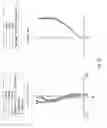
FIG. 1 is a lens layout and optical path diagram of an image capturing lens assembly in accordance with a first embodiment of the present invention;
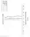
FIG. 2A is a longitudinal spherical aberration diagram of an image capturing lens assembly in accordance with the first embodiment of the present invention;
FIG. 2B is an astigmatic field curves diagram and a distortion diagram of an image capturing lens assembly in accordance with the first embodiment of the present invention;
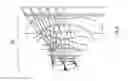
FIG. 3 is a lens layout and optical path diagram of an image capturing lens assembly in accordance with a second embodiment of the present invention;
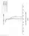
FIG. 4A is a longitudinal spherical aberration diagram of an image capturing lens assembly in accordance with the second embodiment of the present invention;
FIG. 4B is an astigmatic field curves diagram and a distortion diagram of an image capturing lens assembly in accordance with the second embodiment of the present invention;
FIG. 5 is a lens layout and optical path diagram of an image capturing lens assembly in accordance with the second embodiment of the present invention;
FIG. 6A is a longitudinal spherical aberration diagram of an image capturing lens assembly in accordance with the second embodiment of the present invention;
FIG. 6B is an astigmatic field curves diagram and a distortion diagram of an image capturing lens assembly in accordance with the second embodiment of the present invention;
FIG. 7 is a lens layout and optical path diagram of an image capturing lens assembly in accordance with the second embodiment of the present invention;
FIG. 8A is a longitudinal spherical aberration diagram of an image capturing lens assembly in accordance with the second embodiment of the present invention;
FIG. 8B is an astigmatic field curves diagram and a distortion diagram of an image capturing lens assembly in accordance with the second embodiment of the present invention;
FIG. 9 is a lens layout and optical path diagram of an image capturing lens assembly in accordance with the second embodiment of the present invention;
FIG. 10A is a longitudinal spherical aberration diagram of an image capturing lens assembly in accordance with the second embodiment of the present invention; and
FIG. 10B is an astigmatic field curves diagram and a distortion diagram of an image capturing lens assembly in accordance with the second embodiment of the present invention.
FIG. 11 indicates the distance of TTL and BFL of an image capturing lens assembly of the present invention.
DETAILED DESCRIPTION OF THE INVENTION
The present invention will now be described in detail with reference to the accompanying drawings, wherein the same reference numerals will be used to identify the same or similar elements throughout the several views. It should be noted that the drawings should be viewed in the direction of orientation of the reference numerals.
Detailed structural parameters of the first embodiment of the lens are shown in FIG. 1 and provided in Table 1. Surface radii and axial distances are shown in millimeters (mm). The surfaces are identified according to the corresponding drawing reference, from the object side to the image side as shown. The aspheric surfaces are the surfaces S6-S7-S10-S11-S12 and S13 given in Table 1 and described by the following equation:
z = ch 2 1 + [ 1 - ( k + 1 ) c 2 h 2 ] 1 / 2 + A h 4 + Bh 6 + Ch 8 + Dh 10 + Eh 12 + Fh 14 + Gh 16
where:
Z is the surface sag;
c is curvature;
k is conic constant;
h is the vertical distance from the lens surface to the optical axis; and
A, B, C, D, E, F and G are aspheric coefficients. The aspheric coefficients A, B, C, D, E, F and G are given in Table 2.
FIG. 1 is a lens layout and optical path diagram of the image capturing lens assembly in accordance with a first embodiment of the present invention. The image capturing lens assembly 10 includes a stop S1 (STO), a first lens element L11, a second lens element L12, a third lens element L13, a fourth lens element L14, a fifth lens element L15 and an optical filter OF1, all of which are arranged in sequence from an object side to an image side along an optical axis OA1. An image sensor 11 is disposed between the optical filter OF1 and the image side. The first lens element L11 is made of glass material. The first lens element L11 is a convex-concave lens with positive refractive power, the convex surface S2 of the first lens element L11 faces the object side of the image capturing lens assembly 10, and the concave surface S3 of the first lens element L11 faces the image side of the image capturing lens assembly 10. The second lens element L12 is made of plastic material. The second lens element L12 is a convex-concave lens with negative refractive power, the convex surface S4 of the second lens element L12 faces the object side of the image capturing lens assembly 10, and the concave surface S5 of the second lens element L12 faces the image side of the image capturing lens assembly 10. The third lens element L13 is made of plastic material. The third lens L13 element is a convex -convex lens with positive refractive power, the convex surface S6 of the third lens element L13 faces the object side of the image capturing lens assembly 10, and the convex surface S7 of the third lens element L13 faces the image side of the image capturing lens assembly 10. The convex surface S6 and the convex surface S7 both are aspheric surfaces. The convex surface S6 of said third lens element L13 has at least one inflection point between the optical axis and an edge of said third lens element L13. The fourth lens element L14 is made of plastic material. The fourth lens element L14 is a concave-convex lens with negative refractive power, the concave surface S8 of the fourth lens element L14 faces the object side of the image capturing lens assembly 10, and the convex surface S9 of the fourth lens element L14 faces the image side of the image capturing lens assembly 10. The fifth lens element L15 is made of plastic material. The fifth lens element L15 is a concave-convex lens with positive refractive power, the concave surface S10 of the fifth lens element L15 faces the object side, and the convex surface S11 of the fifth lens element L15 faces the image side, wherein both of the concave surface S10 and convex surface S11 are aspheric surfaces. The sixth lens element L16 is made of plastic material. The sixth lens element L16 is a concave-concave lens with negative refractive power, the surface S12 of the sixth lens element L16 faces the object side, and the surface S13 of the sixth lens element L16 faces the image side, wherein both of the surface S12 and surface S13 are aspheric surfaces. The concave surface S13 has at least one inflection point between the optical axis and an edge of said sixth lens element L16.
The optical filter OF1 is made of glass material. The surface S14 and surface S15 of the optical filter OF1 both are plane surfaces. The image sensor 11 includes a sensor element (not shown).
The image capturing lens assembly 10 of the first embodiment of the present invention is provided with the optical specifications shown in Table 1, which include the focal length, F-number, Total Axial Length, radius of curvature of each lens surface, thickness of each lens, refractive index of each lens and Abbe number of each lens.
| TABLE 1 |
| Focus Length = 4.290 mm, F-number = 2.05 |
| Total Axial Length = 5.433 mm |
| Radius of | |||||
| Surface | Curvature | Thickness | Focus Length | ||
| number | (mm) | (mm) | Nd | Vd | (mm) |
| OBJ | Infinity | Infinity | |||
| S1(STO) | Infinity | −0.304407 | |||
| S2 | 2.035556 | 0.445063 | 1.666 | 55.066 | 4.899 |
| S3 | 4.906115 | 0.088751 | |||
| S4 | 3.629075 | 0.219358 | 1.640 | 23.527 | −11.890 |
| S5 | 2.406256 | 0.403993 | |||
| S6 | 14.355461 | 0.615551 | 1.544 | 56.094 | 7.846 |
| S7 | −6.029564 | 0.535193 | |||
| S8 | −1.798168 | 0.298438 | 1.640 | 23.527 | −9.497 |
| S9 | −2.709254 | 0.034174 | |||
| S10 | −21.837734 | 0.622440 | 1.535 | 55.711 | 3.350 |
| S11 | −1.680993 | 0.679152 | |||
| S12 | −9.874585 | 0.409935 | 1.535 | 55.711 | −3.062 |
| S13 | 2.004740 | 0.23 | |||
| S14 | Infinity | 0.145 | 1.517 | 64.167 | |
| S15 | Infinity | 0.705637 | |||
| TABLE 2 | |||||
| Surface | k | A | B | C | |
| number | D | E | F | G | |
| S2 | −0.77963 | 0.015045 | 0.011639 | −0.00371 | |
| 0.000258 | 0.004086 | −0.00067 | 0 | ||
| S3 | 5.226127 | −0.03827 | 0.03041 | 0.017873 | |
| −0.04854 | 0.048415 | −0.01774 | 0 | ||
| S4 | 1.556924 | −0.10167 | 0.093473 | −0.03026 | |
| −0.01649 | 0.035453 | −0.02007 | 0 | ||
| S5 | −1.13035 | −0.03958 | 0.065005 | −0.03746 | |
| 0.040416 | −0.02105 | 0.003384 | 0 | ||
| S6 | 0.268265 | −0.02575 | −0.05375 | 0.030347 | |
| 0.021341 | −0.06264 | 0.030591 | 0 | ||
| S7 | −1.09192 | −0.03321 | −0.03457 | −0.00246 | |
| 0.006557 | −0.00526 | 0.001493 | 0 | ||
| S8 | −0.2748 | 0.055557 | −0.10699 | 0.090366 | |
| −0.03211 | 0.008007 | −0.00134 | 0 | ||
| S9 | 0 | −0.01 | −0.03699 | 0.038258 | |
| −0.00829 | −0.00041 | 0.000227 | 0 | ||
| S10 | −14.8217 | −0.0549 | 0.016496 | −0.00305 | |
| 0.000327 | −0.0004 | 9.3E−05 | 0 | ||
| S11 | −0.73179 | 0.071355 | −0.03239 | 0.013139 | |
| −0.00251 | 0.000254 | −1.6E−05 | 0 | ||
| S12 | 0 | −0.06215 | 0.012503 | −0.00058 | |
| −3.3E−05 | 1.97E−06 | 6.43E−08 | 0 | ||
| S13 | −9.4581 | −0.03722 | 0.007015 | −0.00102 | |
| 9.09E−05 | −4.9E−06 | 1.31E−07 | 0 | ||
V1 is an Abbe number of said first lens element to d light, N1 is a refractivity of said first lens element to d light, wherein d light is a light with a wavelength of 587.6 nm, TTL is a distance along the optical axis from a surface of said first lens element that faces the object side of the image capturing lens assembly to an image sensor, BFL is a distance along the optical axis from a surface of said sixth lens element that faces the image side of the image capturing lens assembly to the image sensor, are shown in FIG. 11, f is a focal length of said lens assembly, f6 is a focal length of said sixth lens element, f3 is a focal length of the third lens element, and f4 is a focal length of the fourth lens element. In the image capturing lens assembly 10, the focal length f =4.290 mm, BFL=1.081 mm, TTL=5.433 mm, f3=7.846 mm, f4=−9.497 mm, f6=−3.062 mm, V1=55.066, and N1=1.666, which can be seen in Table 1. As for BFL, 0.23+0.145+0.705637=1.081. The calculated values of various conditions fully satisfy the following requirements:
20<V1/N<35 (1)
0.15<BFL/TTL<0.25 (2)
−2<f/f6<−0.5 (3)
−1<f3/f4<−0.5 (4)
By the above arrangements of the lenses and stop STO, the image capturing lens assembly 10 can meet the requirements of optical performance as seen in FIGS. 2A and 2B, wherein FIG. 2A shows the longitudinal spherical aberration of the image capturing lens assembly 10 of the present embodiment, FIG. 2B shows the astigmatic field curves of the image capturing lens assembly 10, and FIG. 2B also shows the distortion of the image capturing lens assembly 10.
It can be seen from FIG. 2A that the longitudinal spherical aberration in the present embodiment ranges between −0.1 mm to 0.1 mm for the wavelength range between 0.436 μm to 0.656 μm. It can be seen from FIG. 2B that the astigmatic field curves of tangential direction and sagittal direction in the present embodiment ranges between −0.1 mm to 0.1 mm. It can be also seen from FIG. 2B that the distortion in the present embodiment does not exceed ±2%. It is clear that the longitudinal spherical aberration, the astigmatic field curves and the distortion of the image capturing lens assembly 10 of the present embodiment can be corrected effectively and results in better optical performance.
If the value of V1/N1 is greater than 35, the refractive power of the first lens will become less than 1.666, and it will become difficult to shorten the total length of the imaging lens. If the value of V1/N1 is less than 20, the refractive power of the first lens will become greater than 1.666, and it will become difficult to shorten the total length of the imaging lens.
Detailed structural parameters of the second embodiment of the lens are shown in FIG. 3 and provided in Table 3. Surface radii and axial distances are shown in millimeters (mm). The surfaces are identified according to the corresponding drawing reference, from the object side to the image side as shown. The aspheric surfaces are the surfaces S6-S7-S10-S11-S12 and S13 given in Table 3 and described by the following equation:
z = ch 2 1 + [ 1 - ( k + 1 ) c 2 h 2 ] 1 / 2 + A h 4 + Bh 6 + Ch 8 + Dh 10 + Eh 12 + Fh 14 + Gh 16
Where:
Z is the surface sag;
c is curvature of each lens;
k is conic constant;
h is the vertical distance from the lens surface to the optical axis; and
A, B, C, D, E, F and G are aspheric coefficients. The aspheric coefficients A, B, C, D, E, F and G are given in Table 4.
FIG. 3 is a lens layout and optical path diagram of the image capturing lens assembly in accordance with a second embodiment of the present invention. The image capturing lens assembly 20 includes a stop S2 (STO),a first lens L21, a second lens L22, a third lens L23, a fourth lens L24, a fifth lens L25 and an optical filter OF2, all of which are arranged in sequence from an object side to an image side along an optical axis OA2. An image sensor 21 is disposed between the optical filter OF2 and the image side. The first lens L21 is made of glass material. The first lens L21 is a convex-concave lens with positive refractive power, the convex surface S22 of the first lens L21 faces the object side of the image capturing lens assembly 20, and the concave surface S23 of the first lens L21 faces the image side of the image capturing lens assembly 20. The second lens L22 is made of plastic material. The second lens L22 is a convex-concave lens with negative refractive power, the convex surface S24 of the second lens L22 faces the object side of the image capturing lens assembly 20, and the concave surface S25 of the second lens L22 faces the image side of the image capturing lens assembly 20. The third lens L23 is made of plastic material. The third lens L23 is a concave-convex lens with positive refractive power, the concave surface S26 of the third lens L23 faces the object side of the image capturing lens assembly 20, and the convex surface S27 of the third lens L23 faces the image side of the image capturing lens assembly 20. The concave surface S26 and the convex surface S27 both are aspheric surfaces. The fourth lens L24 is made of plastic material. The fourth lens L24 is a concave-convex lens with negative refractive power, the concave surface S28 of the fourth lens L24 faces the object side of the image capturing lens assembly 20, and the convex surface S29 of the fourth lens L24 faces the image side of the image capturing lens assembly 20. The fifth lens L25 is made of plastic material. The fifth lens L25 is a concave-convex lens with positive refractive power, the surface S210 of the fifth lens L25 faces the object side, and the surface S211 of the fifth lens L25 faces the image side, wherein both of the surface S210 and surface S211 are aspheric surfaces. The sixth lens L26 is made of plastic material. The sixth lens L26 is a concave-concave lens with negative refractive power, the surface S212 of the sixth lens L26 faces the object side, and the surface S213 of the sixth lens L26 faces the image side, wherein both of the surface S212 and surface S213 are aspheric surfaces. The concave surface S213 has at least one inflection point between the optical axis and an edge of said sixth lens element L26.
The optical filter OF2 is made of glass material. The surface S214 and surface S215 of the optical filter OF2 both are plane surfaces. The image sensor 21 includes a sensor element (not shown).
The image capturing lens assembly 20 of the second embodiment of the present invention is provided with the optical specifications shown in Table 3, which include the focal length, F-number, Total Axial Length, surface number, radius of curvature of each lens surface, thickness of each lens, refractive index of each lens and Abbe number of each lens.
| TABLE 3 |
| Focus Length = 4.488 mm, F-number = 2.04 |
| Total Axial Length = 5.680 mm |
| Radius of | |||||
| Surface | Curvature | Thickness | Focus Length | ||
| number | (mm) | (mm) | Nd | Vd | (mm) |
| OBJ | Infinity | Infinity | |||
| S1(STO) | Infinity | −0.310658 | |||
| S2 | 2.141276 | 0.517963 | 1.666 | 55.066 | 4.026 |
| S3 | 9.453879 | 0.082276 | |||
| S4 | 9.635950 | 0.219644 | 1.640 | 23.527 | −11.214 |
| S5 | 4.098793 | 0.386119 | |||
| S6 | −104.008867 | 0.846604 | 1.544 | 56.094 | 12.056 |
| S7 | −6.219849 | 0.210050 | |||
| S8 | −3.933085 | 0.299798 | 1.640 | 23.527 | −12.463 |
| S9 | −7.918380 | 0.174335 | |||
| S10 | −20.026908 | 0.781276 | 1.535 | 55.711 | 3.435 |
| S11 | −1.714473 | 0.552967 | |||
| S12 | −3.493090 | 0.534878 | 1.535 | 55.711 | −2.784 |
| S13 | 2.761380 | 0.2 | |||
| S14 | Infinity | 0.145 | 1.517 | 64.167 | |
| S15 | Infinity | 0.729133 | |||
| TABLE 4 | ||||
| Surface | k | A | B | C |
| number | D | E | F | G |
| S2 | −0.88533 | 0.013661 | 0.006513 | −0.00261 |
| −0.00015 | 0.002641 | −0.0012 | 0 | |
| S3 | 12.97105 | −0.03308 | 0.019936 | 0.024113 |
| −0.05161 | 0.039746 | −0.01227 | 0 | |
| S4 | 31.42672 | −0.09237 | 0.105661 | −0.04578 |
| −0.0234 | 0.040717 | −0.0154 | 0 | |
| S5 | −2.99452 | −0.05007 | 0.077926 | −0.05807 |
| 0.032998 | −0.01632 | 0.007215 | 0 | |
| S6 | −2244.44 | −0.03609 | −0.04357 | 0.021462 |
| 0.031592 | −0.05974 | 0.025855 | 0 | |
| S7 | −52.776 | −0.05057 | −0.04078 | 0.005783 |
| 0.005959 | −0.00413 | 0.000812 | 0 | |
| S8 | 6.85058 | 0.03421 | −0.10758 | 0.075422 |
| −0.03084 | 0.008827 | −0.00132 | 0 | |
| S9 | 0 | −0.00608 | −0.05152 | 0.035071 |
| −0.00896 | −0.00014 | 0.00038 | 0 | |
| S10 | 78.61808 | −0.04853 | 0.003439 | −7.9E−06 |
| 0.000121 | −0.00074 | 0.000234 | 0 | |
| S11 | −0.68733 | 0.04488 | −0.01698 | 0.011015 |
| −0.00278 | 0.00032 | −1.6E−05 | 0 | |
| S12 | 0 | −0.02691 | 0.009054 | −0.00051 |
| −2.3E−05 | 2.1E−06 | 2.75E−08 | 0 | |
| S13 | −11.5165 | −0.03092 | 0.006713 | −0.00116 |
| 0.000119 | −7.1E−0 | 61.9E−07 | 0 | |
In the image capturing lens assembly 20, the focal length f=4.488 mm, BFL=1.074 mm, TTL=5.680 mm, f3=12.056 mm, f4=−12.463mm, f6=−2.784 mm, V1=55.066,and N1=1.666, which can be seen in table 3. As for BFL, 0.2+0.145+0.729133=1.074. The calculated values of various conditions fully satisfy the following requirements:
20<V1/N1<35 (1)
0.15<BFL/TTL<0.25 (2)
−2<f/f6<−0.5 (3)
−1<f3/f4<−0.5 (4)
By the above arrangements of the lenses and stop STO, the image capturing lens assembly 20 of the present embodiment can meet the requirements of optical performance as seen in FIGS. 4A and 4B, wherein FIG. 4A shows the longitudinal spherical aberration of the image capturing lens assembly 10 of the present embodiment, FIG. 4B shows the astigmatic field curves of the image capturing lens assembly 10 of the present embodiment and FIG. 4B also shows the distortion of the image capturing lens assembly 10 of the present embodiment. If the value of V1/N1 is greater than 35, the refractive power of the first lens will become less than 1.666, and it will become difficult to shorten the total length of the imaging lens. If the value of V1/N1 is less than 20, the refractive power of the first lens will become greater than 1.666, and it will become difficult to shorten the total length of the imaging lens.
It can be seen from FIG. 4A that the longitudinal spherical aberration in the present embodiment ranges between −0.1 mm to 0.1 mm for the wavelength range between 0.436 μm to 0.656 μm. It can be seen from FIG. 4B that the astigmatic field curves of tangential direction and sagittal direction in the present embodiment ranges between −0.1 mm to 0.1 mm. It can be also seen from FIG. 4B that the distortion in the present embodiment does not exceed ±2%. It is clear that the longitudinal spherical aberration, the astigmatic field curves and the distortion of the image capturing lens assembly 10 of the present embodiment can be corrected effectively and results in better optical performance.
Referring to FIG. 5, FIG. 6, table 5 and table 6 are a third embodiment of the present invention. In this embodiment, the focal length f=4.262 mm, BFL=1.033 mm, TTL=5.431 mm, f3=5.106 mm, f4=−6.511 mm, f6=−4.299 mm, V1=57.333, and N1=1.658, which can be seen in Table 5. As for BFL, 0.25+0.145+0.638283=1.033. The calculated values of various conditions fully satisfy the following requirements:
20<V1/N1<35 (1)
0.15<BFL/TTL<0.25 (2)
−2<f/f6<−0.5 (3)
−1<f3/f4<−0.5 (4)
By the above arrangements of the lenses and stop STO, the image capturing lens assembly 30 of the present embodiment can meet the requirements of optical performance as seen in FIGS. 6A and 6B. The description of the third embodiment is similar to the description of the first and second embodiment, and is not repeated here. The image capturing lens assembly 30 has six lenses. In an embodiment, a seventh lens element can be added between the sixth lens element and the image side.
| TABLE 5 |
| Focus Length = 4.262 mm, F-number = 2.04 |
| Total Axial Length = 5.431 mm |
| Radius of | |||||
| Surface | Curvature | Thickness | Focus Length | ||
| number | (mm) | (mm) | Nd | Vd | (mm) |
| OBJ | Infinity | Infinity | |||
| S1(STO) | Infinity | −0.316141 | |||
| S2 | 1.915520 | 0.457334 | 1.658 | 57.333 | 5.246 |
| S3 | 3.872415 | 0.310759 | |||
| S4 | 6.148997 | 0.214675 | 1.640 | 23.527 | −12.312 |
| S5 | 3.420655 | 0.249747 | |||
| S6 | 8.468975 | 0.635668 | 1.544 | 56.094 | 5.106 |
| S7 | −4.057522 | 0.372826 | |||
| S8 | −0.987937 | 0.366003 | 1.640 | 23.527 | −6.511 |
| S9 | −1.478943 | 0.079935 | |||
| S10 | 2.351900 | 0.576456 | 1.535 | 55.711 | 4.560 |
| S11 | 52.433536 | 0.646401 | |||
| S12 | −56.592211 | 0.488234 | 1.535 | 55.711 | −4.299 |
| S13 | 2.417712 | 0.25 | |||
| S14 | Infinity | 0.145 | 1.517 | 64.167 | |
| S15 | Infinity | 0.638283 | |||
| TABLE 6 | |||||
| Surface | k | A | B | C | |
| number | D | E | F | G | |
| S2 | −0.6898 | 0.015972 | 0.008764 | −0.00051 | |
| 0.001565 | 0.001915 | −0.00286 | 0 | ||
| S3 | 1.794042 | −0.0261 | 0.006236 | 0.016396 | |
| −0.04751 | 0.040703 | −0.0169 | 0 | ||
| S4 | −59.4441 | −0.12713 | 0.059558 | 0.017351 | |
| −0.04555 | 0.015875 | −0.0004 | 0 | ||
| S5 | −14.636 | −0.08857 | 0.064709 | −0.00422 | |
| 0.03996 | −0.06167 | 0.027112 | 0 | ||
| S6 | 0 | −0.01321 | −0.0333 | 0.016009 | |
| 0.017941 | −0.02798 | 0.010209 | 0 | ||
| S7 | −4.15704 | 0.016763 | −0.01187 | −0.01002 | |
| 0.008227 | −0.00394 | 0.001412 | 0 | ||
| S8 | −2.35523 | 0.123794 | −0.12571 | 0.093039 | |
| −0.03497 | 0.007437 | −0.00081 | 0 | ||
| S9 | −3.60075 | 0.020482 | −0.04724 | 0.037527 | |
| −0.00703 | −0.00049 | 0.000164 | 0 | ||
| S10 | −0.47867 | −0.04419 | 0.001175 | −0.00354 | |
| 0.001381 | −0.00027 | 2.2E−05 | 0 | ||
| S11 | 0 | 0.088018 | −0.05608 | 0.015124 | |
| −0.00246 | 0.000216 | −7.4E−06 | 0 | ||
| S12 | 0 | −0.06576 | 0.011729 | −0.0006 | |
| −2.1E−05 | 3.46E−06 | −1.2E−07 | 0 | ||
| S13 | −11.1135 | −0.04076 | 0.006544 | −0.00074 | |
| 7.7E−05 | −6.5E−06 | 2.39E−07 | 0 | ||
FIG. 7, FIG. 8, Table 7 and Table 8 illustrate a fourth embodiment of the present invention. In the image capturing lens assembly 40, the focal length f=4.276 mm, BFL=1.039 mm, TTL=5.281 mm, f3=9.022 mm, f4=−10.572 mm, f6=−2.417 mm, V1=55.066, and N1=1.666, which can be seen in Table 7. As for BFL, 0.213869+0.145+0.680262=1.039 The calculated values of various conditions fully satisfy the following requirements:
20<V1/N1<35 (1)
0.15<BFL/TTL<0.25 (2)
2<f/f6<−0.5 (3)
−1<f3/f4<−0.5 (4)
By the above arrangements of the lenses and stop STO, the image capturing lens assembly 40 of the present embodiment can meet the requirements of optical performance as seen in FIGS. 8A and 8B. The description of the fourth embodiment is similar to the description of the first and second embodiment, so omitting the description of the fourth embodiment. The image capturing lens assembly 40 has six lenses. In an embodiment, a seventh lens element can be added between the sixth lens element and the image side.
| TABLE 7 |
| Focus Length = 4.276 mm, F-number = 2.04 |
| Total Axial Length = 5.28069 mm |
| Radius of | |||||
| Surface | Curvature | Thickness | Focus Length | ||
| number | (mm) | (mm) | Nd | Vd | (mm) |
| OBJ | Infinity | Infinity | |||
| S1(STO) | Infinity | −0.332120 | |||
| S2 | 1.905528 | 0.540911 | 1.666 | 55.066 | 3.962 |
| S3 | 6.016700 | 0.136277 | |||
| S4 | 7.152222 | 0.24 | 1.640 | 23.527 | −8.924 |
| S5 | 3.150216 | 0.362078 | |||
| S6 | 30.000000 | 0.621125 | 1.535 | 55.711 | 9.022 |
| S7 | −5.740368 | 0.176538 | |||
| S8 | −3.074355 | 0.273590 | 1.640 | 23.527 | −10.572 |
| S9 | −5.785661 | 0.280502 | |||
| S10 | −35.501860 | 0.583695 | 1.535 | 55.711 | 2.927 |
| S11 | −1.514786 | 0.484362 | |||
| S12 | −2.877702 | 0.542479 | 1.535 | 55.711 | −2.417 |
| S13 | 2.522926 | 0.213869 | |||
| S14 | Infinity | 0.145 | 1.517 | 64.167 | |
| S15 | Infinity | 0.680262 | |||
| TABLE 8 | |||||
| Surface | k | A | B | C | |
| number | D | E | F | G | |
| S2 | −0.81688 | 0.017935 | 0.013283 | −0.00286 | |
| −0.0003 | 0.004457 | −0.00104 | 0 | ||
| S3 | 5.263002 | −0.04665 | 0.030028 | 0.036002 | |
| −0.09565 | 0.094791 | −0.0367 | 0 | ||
| S4 | −22.9882 | −0.13254 | 0.157434 | −0.06024 | |
| −0.04892 | 0.081115 | −0.03988 | 0 | ||
| S5 | −10.5294 | −0.05257 | 0.129335 | −0.08867 | |
| 0.064475 | −0.03896 | 0.015469 | 0 | ||
| S6 | 6.324669 | −0.05627 | −0.06234 | 0.033089 | |
| 0.048355 | −0.1326 | 0.072517 | 0 | ||
| S7 | −90.0001 | −0.0632 | −0.08129 | 0.014747 | |
| 0.012894 | −0.01101 | 0.003732 | 0 | ||
| S8 | 3.608043 | 0.039541 | −0.16214 | 0.135774 | |
| −0.05518 | 0.021801 | −0.00487 | 0 | ||
| S9 | 0 | −0.03738 | −0.0605 | 0.060356 | |
| −0.01733 | −0.00052 | 0.000928 | 0 | ||
| S10 | −1.0241 | −0.056 | 0.000435 | 0.000586 | |
| 0.000761 | −0.00165 | 0.000467 | 0 | ||
| S11 | −0.72238 | 0.069092 | −0.02638 | 0.018292 | |
| −0.00531 | 0.000701 | −3.9E−05 | 0 | ||
| S12 | 0 | −0.02191 | 0.013075 | −0.001 | |
| −4.7E−05 | 6.47E−06 | 1.55E−07 | 0 | ||
| S13 | 15.1597 | −0.03625 | 0.008696 | −0.00177 | |
| 0.000216 | −1.6E−05 | 5.53E−07 | 0 | ||
FIG. 9, FIG. 10, Table 9 and Table 10 illustrate a fifth embodiment of the present invention. In the image capturing lens assembly 50, the focal length f=4.394 mm, BFL=1.149 mm, TTL=5.280 mm, f3=8.137 mm, f4=−10.673 mm, f6=−2.410 mm, V1=55.418, and N1=1.669, which can be seen in Table 9. As for BFL, 0.198183+0.145+0.805775=1.149. The calculated values of various conditions fully satisfy the following requirements:
20<V1/N1<35 (1)
0.15<BFL/TTL<0.25 (2)
−2<f/f6<−0.5 (3)
−1<f3/f4<−0.5 (4)
By the above arrangements of the lenses and stop STO, the image capturing lens assembly 50 of the present embodiment can meet the requirements of optical performance as seen in FIGS. 10A and 10B. The description of the fifth embodiment is similar to the description of the first and second embodiment, so omitting the description of the fifth embodiment. The image capturing lens assembly 50 has six lenses. In an embodiment, a seventh lens element can be added between the sixth lens element and the image side.
| TABLE 9 |
| Focus Length = 4.394 mm, F-number = 2.04 |
| Total Axial Length = 5.28000 mm |
| Radius of | |||||
| Surface | Curvature | Thickness | Focus Length | ||
| number | (mm) | (mm) | Nd | Vd | (mm) |
| OBJ | Infinity | Infinity | |||
| S1(STO) | Infinity | −0.361414 | |||
| S2 | 1.845761 | 0.547447 | 1.669 | 55.418 | 4.280 |
| S3 | 4.539083 | 0.136004 | |||
| S4 | 6.773884 | 0.27 | 1.643 | 22.465 | −11.467 |
| S5 | 3.490992 | 0.326584 | |||
| S6 | 13.375805 | 0.653316 | 1.535 | 55.711 | 8.137 |
| S7 | −6.384412 | 0.158100 | |||
| S8 | −2.927268 | 0.295646 | 1.643 | 22.465 | −10.673 |
| S9 | −5.270166 | 0.294125 | |||
| S10 | −34.740008 | 0.538441 | 1.535 | 55.711 | 3.003 |
| S11 | −1.550474 | 0.394455 | |||
| S12 | −2.712102 | 0.516925 | 1.535 | 55.711 | −2.410 |
| S13 | 2.642322 | 0.198183 | |||
| S14 | Infinity | 0.145 | 1.517 | 64.167 | |
| S15 | Infinity | 0.805775 | |||
| TABLE 10 | |||||
| Surface | k | A | B | C | |
| number | D | E | F | G | |
| S2 | −0.85262 | 0.01775 | 0.01309 | −0.0033 | |
| −0.00078 | 0.00447 | −0.001 | 0 | ||
| S3 | −0.01054 | −0.0541 | 0.03217 | 0.03593 | |
| −0.1031 | 0.10606 | −0.03949 | 0 | ||
| S4 | −17.0554 | −0.13872 | 0.1594 | −0.06359 | |
| −0.0499 | 0.09482 | −0.04441 | 0 | ||
| S5 | −13.7146 | −0.06149 | 0.1331 | −0.09271 | |
| 0.06907 | −0.04623 | 0.02061 | 0 | ||
| S6 | −89.9062 | −0.06652 | −0.05056 | 0.02858 | |
| 0.05389 | −0.14574 | 0.07951 | 0 | ||
| S7 | −90 | −0.05799 | −0.0952 | 0.01926 | |
| 0.01602 | −0.01182 | 0.00338 | 0 | ||
| S8 | 3.98719 | 0.05335 | −0.1687 | 0.14273 | |
| −0.06148 | 0.02403 | −0.00467 | 0 | ||
| S9 | 0 | −0.029 | −0.06586 | 0.06264 | |
| −0.01917 | −0.00042 | 0.00111 | 0 | ||
| S10 | −1.0241 | −0.06409 | −0.00445 | −1E−04 | |
| 0.00054 | −0.00202 | 0.00074 | 0 | ||
| S11 | −0.69648 | 0.0749 | −0.02851 | 0.01907 | |
| −0.0058 | 0.00081 | −4.7E−05 | 0 | ||
| S12 | 0 | −0.02202 | 0.01379 | −0.00097 | |
| −5.4E−05 | 4.9E−06 | 4.3E−07 | 0 | ||
| S13 | −17.1998 | −0.03855 | 0.00871 | −0.00189 | |
| 0.00024 | −1.9E−05 | 7.4E−07 | 0 | ||
The image capturing lens assembly has satisfied the condition: 20<V1/N1<35. Therefore, the image capturing lens has a shortened total axial length.
The third lens has a convex surface facing the image side of the image capturing lens assembly and the image capturing lens assembly has satisfied the conditions: −1<f3/f4<−0.5, 0.15<BFL/TTL<0.25 and −2<f/f6<−0.5. Thus, the image capturing lens has an effectively aberration correction and an improved resolution.
The invention being thus described, it will be clear that the same may be varied in many ways. Such variations are not to be regarded as a departure from the spirit and scope of the invention, and all such modifications as would be obvious to one skilled in the art are intended to be included within the scope of the following claims.
Claims
What is claimed is:1. An image capturing lens assembly comprising, in an order from an object side to an image side thereof:
a first lens element with refractive power, wherein
20<V1/N1<35,
where V1 is an Abbe number of the first lens element to d light, and N1 is a refractivity of the first lens element to d light, wherein d light is a light with a wavelength of 587.6 nm;a second lens element with refractive power;
a third lens element with positive refractive power and having a convex surface facing the image side of the image capturing lens assembly;
a fourth lens element with refractive power;
a fifth lens element with refractive power; and
a sixth lens element with refractive power.
2. The image capturing lens assembly according to claim 1, wherein
−0.01<I/R5<0.2,
where R5 is a curvature radius of a surface of said third lens element that is opposite to the convex surface of said third lens element.
3. The image capturing lens assembly according to claim 1, wherein the surface of said third lens element that is opposite to the convex surface of said third lens element includes a concave surface.
4. The image capturing lens assembly according to claim 1, wherein the third lens element further includes a convex surface facing the object side, the convex surface of the object side includes one inflection point.
5. The image capturing lens assembly according to claim 4, wherein the inflection point is located between the optical axis and an edge of said third lens element.
6. The image capturing lens assembly according to claim 1, wherein the first lens element is a convex-concave lens, the second lens element is a convex-concave lens, the fourth lens element is a concave-convex lens, and the sixth lens element is a concave-concave lens.
7. The image capturing lens assembly according to claim 1, wherein a refractive power of the first lens element is positive, a refractive power of the second lens element is negative, a refractive power of the fourth lens element is negative, a refractive power of the fifth lens element is positive, and a refractive power of the sixth lens element is negative.
8. The image capturing lens assembly according to claim 1, wherein
−1<f3/f4<−0.5,
where f3 is a focal length of the third lens element, and f4 is a focal length of the fourth lens element.
9. The image capturing lens assembly according to claim 1, wherein
0.15<BFL/TTL<0.25,
where TTL is a distance along the optical axis from a surface of said first lens element that faces the object side of the image capturing lens assembly to an image sensor, and BFL is a distance along the optical axis from a surface of said sixth lens element that faces the image side of the image capturing lens assembly to the image sensor.
10. The image capturing lens assembly according to claim 1, wherein
−2<f/f6<−0.5,
where f is a focal length of said lens assembly, and f6 is a focal length of said sixth lens element.
11. The image capturing lens assembly according to claim 1, wherein at least one of the third lens element, the fifth lens element and the sixth lens element has at least one aspheric surface.
12. An image capturing lens assembly, comprising in order from an object side
a first lens element with positive refractive and a convex surface facing the object side of the image capturing lens assembly, wherein
20<V1/N1<35,
where V1 is an Abbe number of the first lens element to d light, and N1 is a reflectivity of the first lens element to d light, wherein d light is a light with a wavelength of 587.6 nm;
a second lens element with refractive power;
a third lens element with refractive power;
a fourth lens element with refractive power, wherein a concave surface that faces the object side of the image capturing lens assembly and a convex surface that is opposite to the concave surface;
a fifth lens element with positive refractive power; and
a sixth lens element with negative refractive power, wherein a concave surface that faces the image side of the image capturing lens assembly, and the concave surface has at least one inflection point and the sixth lens element has at least one aspheric surface.
13. The image capturing lens assembly according to claim 12, wherein said first lens element is made of glass and has a surface-that is opposite to the convex surface of the first lens element.
14. The image capturing lens assembly according to claim 12, wherein the concave surface of said sixth lens element has an inflection point between the optical axis and an edge of said sixth lens element.
15. The image capturing lens assembly according to claim 12, further comprises: a stop located between an end of the image capturing lens assembly at the object side and said first lens element.
16. An image capturing lens assembly, comprising in order from an object side to an image side:
a first lens element with positive refractive;
a second lens element with refractive power;
a third lens element with refractive power;
a fourth lens element with refractive power;
a fifth lens element with refractive power; and
a sixth lens element with refractive power, wherein
20<V1/N1<35,
0.15<BFL/TTL<0.25,
−2<f/f6<−0.5, and
−1<f3/f4<−0.5,
where V1 is an Abbe number of said first lens element to d light, N1 is a refractivity of said first lens element to d light, wherein d light is a light with a wavelength of 587.6 nm, TTL is a distance along the optical axis from a surface of said first lens element that faces the object side of the image capturing lens assembly to an image sensor, BFL is a distance along the optical axis from a surface of said sixth lens element that faces the image side of the image capturing lens assembly to the image sensor, f is a focal length of said lens assembly, f6 is a focal length of said sixth lens element, f3 is a focal length of the third lens element, and f4 is a focal length of the fourth lens element.
17. An image capturing lens assembly in an order along an optical axis from an object side to an image side thereof, comprising:
a first lens element with refractive power;
a second lens element with refractive power;
a third lens element with positive refractive power and having a convex surface facing the image side of the image capturing lens assembly, and having a concave surface that is opposite to the convex surface, wherein
20 <V1/N1<35,
where V1 is an Abbe number of the first lens element to d light, and N1 is a refractivity of the first lens element to d light, wherein d light is a light with a wavelength of 587.6 nm;
a fourth lens element with refractive power;
a fifth lens element with refractive power; and
a sixth lens element with refractive power, wherein
0.15<BFL/TTL<0.25,
where TTL is a distance along the optical axis from a surface of said first lens element that faces the object side of the image capturing lens assembly to an image sensor, and BFL is a distance along the optical axis from a surface of said sixth lens element that faces the image side of the image capturing lens assembly to the image sensor.
18. The image capturing lens assembly according to claim 17, wherein a concave surface of said second lens element that faces the image side of the image capturing lens assembly, said the concave surface of said second lens element is at left of said concave surface of said third lens element, a concave surface of said fourth lens element that faces the object side of the image capturing lens assembly, and said the concave surface of said fourth lens element is at right of said convex surface of said third lens element.
19. The image capturing lens assembly according to claim 18, wherein the sixth lens element further includes a concave surface facing the image side, the concave surface of said sixth lens element includes one inflection point.
20. The image capturing lens assembly according to claim 19, wherein the infection point is located between the optical axis and an edge of the sixth lens element.
Images & Drawings included:


Sources:
- United States Patent and Trademark Office - verify current appl. status at the USPTO↗
Similar patent applications:
- » 20250050603
MANUFACTURING METHOD OF A LENS ASSEMBLY, MANUFACTURING DEVICE OF A LENS ASSEMBLY, AND LENS ASSEMBLY - » 20120182459
Lens assembling method, lens assembly, and image capturing device with the lens assembly - » 20250277956
LENS ASSEMBLY, A LENS UNIT HOLDER FOR A LENS ASSEMBLY AND A METHOD FOR PROVIDING A LENS UNIT FOR THE LENS ASSEMBLY - » 20230127423
LENS ASSEMBLY, IMAGING APPARATUS INCLUDING THE LENS ASSEMBLY, AND ELECTRONIC APPARATUS INCLUDING THE LENS ASSEMBLY - » 20230038551
LENS ASSEMBLY, CAMERA MODULE HAVING A LENS ASSEMBLY FOR MOTOR VEHICLES, AND A METHOD FOR MAKING LENS ASSEMBLY - » 20240219679
Photographing lens assembly, lens assembly driving module and electronic device - » 20210396949
Photographing lens assembly, lens assembly driving module and electronic device - » 20250258354
PHOTOGRAPHING LENS ASSEMBLY, LENS ASSEMBLY DRIVING MODULE AND ELECTRONIC DEVICE - » 20230135916
IMAGING LENS ASSEMBLY, IMAGING LENS ASSEMBLY MODULE, CAMERA MODULE AND ELECTRONIC DEVICE - » 20250052933
IMAGING LENS ASSEMBLY, IMAGING LENS ASSEMBLY MODULE AND ELECTRONIC DEVICE
Recent applications in this class:
- » 20250291158 2025-09-18
IMAGING OPTICAL LENS ASSEMBLY, IMAGING APPARATUS AND ELECTRONIC DEVICE - » 20250291157 2025-09-18
OPTICAL IMAGING LENS ASSEMBLY - » 20250284101 2025-09-11
OPTICAL SYSTEM AND IMAGE PICKUP APPARATUS - » 20250284100 2025-09-11
OPTICAL SYSTEM, IMAGING DEVICE, IN-VEHICLE SYSTEM, AND MOVABLE APPARATUS - » 20250284099 2025-09-11
OPTICAL IMAGING SYSTEM - » 20250284098 2025-09-11
LENS MODULE - » 20250284097 2025-09-11
OPTICAL SYSTEM, CAMERA MODULE, AND ELECTRONIC DEVICE - » 20250284096 2025-09-11
CAMERA OPTICAL LENS - » 20250284095 2025-09-11
CAMERA OPTICAL LENS - » 20250277961 2025-09-04
IMAGING LENS SYSTEM AND CAMERA MODULE
Recent applications for this Assignee:
- » 20170038559 2017-02-09
Wide-angle lens - » 20170038559 2017-02-09
Wide-angle lens - » 20170023773 2017-01-26
Lens assembly - » 20160377840 2016-12-29
Optical lens assembly - » 20160299316 2016-10-13
Infrared ray-tracing lens module - » 20160299316 2016-10-13
Infrared ray-tracing lens module - » 20160299316 2016-10-13
Infrared ray-tracing lens module - » 20160116710 2016-04-28
Lens assembly - » 20160103301 2016-04-14
Wide-angle lens - » 20150331224 2015-11-19
Lens assembly