Mechanical lug with dovetail interlock feature
US20160164194A1
2016-06-09
15/042,341
2016-02-12
✅ Patent granted
US 9,692,145 B2
2017-06-27
-
-
Javaid Nasri
Christopher S. Clancy | James H. Williams | Aimee E. McVady
2036-02-12
Abstract:
The present invention is directed to a mechanical lug with interlocking features that secures an electrical conductor. The mechanical lug has a main body and a mounting tongue extending from the main body. The main body includes an inner flange and an outer flange. The inner flange has a horizontal member and an interlocking member with angled pockets. The outer flange has hooks with a tapered face positioned in the angled pockets of the interlocking member of the inner flange thereby forming a dovetail interlock.
Inventors:
- Francis Seehoffer 2 🇺🇸 New Lenox, IL, United States
- Robert L. Sokol 17 🇺🇸 Orland Park, IL, United States
Assignee:
- PANDUIT CORP. 1,097 🇺🇸 Tinley Park, IL, United States
Applicant:
Interested in similar patents?
Get notified when new applications in this technology area are published.
Classification:
H01R11/12 » CPC further
Individual connecting elements providing two or more spaced connecting locations for conductive members which are, or may be, thereby interconnected, e.g. end pieces for wires or cables supported by the wire or cable and having means for facilitating electrical connection to some other wire, terminal, or conductive member, blocks of binding posts; End pieces or tapping pieces for wires, supported by the wire and for facilitating electrical connection to some other wire, terminal or conductive member End pieces terminating in an eye, hook, or fork
H01R4/30 » CPC main
Electrically-conductive connections between two or more conductive members in direct contact, i.e. touching one another; Means for effecting or maintaining such contact; Electrically-conductive connections having two or more spaced connecting locations for conductors and using contact members penetrating insulation; Clamped connections, spring connections utilising a screw or nut clamping member
H01R4/36 » CPC further
Electrically-conductive connections between two or more conductive members in direct contact, i.e. touching one another; Means for effecting or maintaining such contact; Electrically-conductive connections having two or more spaced connecting locations for conductors and using contact members penetrating insulation; Clamped connections, spring connections utilising a screw or nut clamping member Conductive members located under tip of screw
Description
CROSS-REFERENCE TO RELATED APPLICATIONS
This application is a continuation of U.S. patent application Ser. No. 14/323,038, filed Jul. 3, 2014, and claims priority to U.S. Provisional Application Ser. No. 61/844,501, filed Jul. 10, 2013, the subject matter of which is hereby incorporated by reference in its entirety.
FIELD OF THE INVENTION
The present invention relates to a mechanical lug, and more particularly to a mechanical lug with an interlock feature.
BACKGROUND OF THE INVENTION
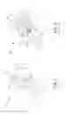
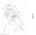
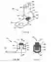
Mechanical lug connectors are used to secure electrical conductors. FIGS. 1, 2, and 3A-C illustrate prior art mechanical lug connectors. The mechanical lug 10 illustrated in FIG. 1 includes a main body 12 with overlapping flanges 14, 16 and a mounting tongue 18. The mechanical lug 10 does not include any interlocking features. As such, the flanges 14, 16 tend to open up and separate from each other when tightening the screw 20 that secures the electrical conductor positioned therein.
The mechanical lug 30 illustrated in FIGS. 2 and 3A-C is an improvement over the mechanical lug 10 illustrated in FIG. 1. The mechanical lug 30 includes a main body 32 with a mounting tongue 42. The main body 32 has an inner flange 34 with a T-shaped cut out 36 and an overlapping outer flange 37 with a T-shaped flange 38. As illustrated in FIG. 3B, the T-shaped flange 38 of the outer flange 37 is positioned within the T-shaped cut out 36 of the inner flange 34. The side walls 40 of the inner flange 34 are weakened due to the T-shaped cut out 36. As a result, when the screw 44 is tightened to secure an electrical conductor, the T-shaped flange 38 pulls upward thereby opening up the lug and separating the flanges from each other.
Thus, the flanges of prior art lugs, such as those discussed above, tend to open up and separate from each other as the screw securing the electrical conductor is being tightened to the specified torque.
Therefore, there is a need for an improved mechanical lug connector with interlocking features that do not separate when a screw is tightened to secure an electrical conductor positioned therein.
SUMMARY OF THE INVENTION
The present invention is directed to a mechanical lug that is used to secure electrical conductors. The mechanical lug has a main body with a mounting tongue extending from the main body. The main body has an inner flange and an overlapping outer flange. The inner flange includes a horizontal member and an interlocking member with angled pockets. The outer flange includes hooks with a tapered face. The hooks of the outer flange are positioned in the angled pockets of the interlocking member of the inner flange to secure the mechanical lug.
BRIEF DESCRIPTION OF THE DRAWINGS
FIG. 1 is a perspective view of a prior art mechanical lug.
FIG. 2 is a perspective view of a prior art mechanical lug.
FIG. 3A is a perspective view of the prior art mechanical lug of FIG. 2 with the outer flange extended prior to overlapping the inner flange.
FIG. 3B is a side view of the prior art mechanical lug of FIG. 2.
FIG. 3C is a cross sectional view of the prior art mechanical lug taken along line 3C-3C of FIG. 3B.
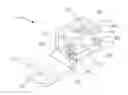
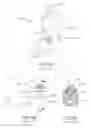
FIG. 4 is a perspective view of the mechanical lug of the present invention.
FIG. 5A is a perspective view of the mechanical lug of FIG. 4 with the outer flange extended prior to overlapping the inner flange.
FIG. 5B is a side view of the mechanical lug of FIG. 4.
FIG. 5C is a cross sectional view of the mechanical lug taken along line 5C-5C of FIG. 5B.
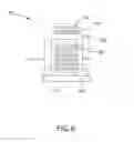
FIG. 6 is a front view of the mechanical lug of FIG. 4.
DETAILED DESCRIPTION
FIGS. 4-6 illustrate the mechanical lug 50 of the present invention. The mechanical lug 50 is an integral piece that includes a main body 52 and a mounting tongue 54. The mounting tongue 54 extends from the main body 52 and includes a hole 56 for receiving a fastener to secure the mechanical lug 50 to a bus bar or other device.
The main body 52 is formed from sheet metal into a generally box shape designed to accommodate various sizes of electrical conductors. The main body 52 includes a bottom 58, an inner flange 62 and an outer overlapping flange 66. The bottom 58 is generally V-shaped with serrations 60 for receiving the electrical conductor. The serrations 60 increase the wire retention when the conductor is installed thereby improving the strength of the mechanical lug 50.
As illustrated in FIG. 5A, the inner flange 62 includes a horizontal member 63 and an interlocking member 64. The interlocking member 64 includes open sides that define angled pockets 65. The outer overlapping flange 66 has two hooks 68 with tapered faces 70 and an opening 69. As illustrated in FIG. 5B, the opening 69 of the outer flange 66 receives the interlocking member 64 of the inner flange 62. The hooks 68 with tapered faces 70 are positioned within the angled pockets 65 formed in the interlocking member 64 of the inner flange 62. The pockets 65 of the interlocking member 64 and the tapered faces 70 of the hooks 68 provide a strong dovetailed interlock.
A tapped hole 72 at the top of the main body 52 extends through both the outer overlapping flange 66 and the inner flange 62. The tapped hole 72 accommodates a set or cap screw 74 for securing electrical conductors in the main body 52.
The dovetailed interlock formed by the inner flange 62 and the outer overlapping flange 66 prevents the main body 52 from separating when the screw 74 is tightened to secure the electrical conductor positioned therein. The interlocking flanges of the mechanical lug of the present invention increase the integrity and the strength of the mechanical lug when compared to prior art lugs. Additionally, the mechanical lug of the present invention is cost effective and easy to manufacture.
Furthermore, while the particular preferred embodiments of the present invention have been shown and described, it will be obvious to those skilled in the art that changes and modifications may be made without departing from the teaching of the invention. The matter set forth in the foregoing description and accompanying drawings is offered by way of illustration only and not as limitation. The actual scope of the invention is intended to be defined in the following claims when viewed in their proper perspective based on the prior art.
Claims
1. A mechanical lug for securing electrical conductors, the mechanical lug comprising:
a main body having an inner flange and an outer flange;
wherein the inner flange having a horizontal member and an interlocking member, each side of the interlocking member being an open side defining angled pockets; and
wherein the outer flange having hooks with a tapered face, the hooks of the outer flange are positioned in the open sides of the inner flange and the hooks of the outer flange engage the angled pockets of the interlocking member of the inner flange.
2. The mechanical lug of claim 1, wherein the outer flange over laps the inner flange.
3. The mechanical lug of claim 1, wherein the hooks of the outer flange are L-shaped.
4. The mechanical lug of claim 1, wherein the hooks of the outer flange define an opening, the opening receives the interlocking member of the inner flange.
5. The mechanical lug of claim 1, wherein the inner flange and outer flange mate to form a dovetail interlock.
6. A mechanical lug for securing electrical conductors, the mechanical lug comprising:
a main body having an outer flange and an inner flange,
wherein the inner flange having a horizontal member and an interlocking member with open sides that form angled pockets; and
wherein the outer flange having hooks with a tapered face, the tapered face of the hooks engage the angled pockets of the interlocking member of the inner flange to form a dovetail interlock.
7. The mechanical lug of claim 6, wherein the interlocking member is T-shaped.
Images & Drawings included:
Sources:
- United States Patent and Trademark Office - verify current appl. status at the USPTO↗
Similar patent applications:
- » 20150017843
Mechanical lug with dovetail interlock feature
Recent applications in this class:
- » 20240055782 2024-02-15
Terminal Fitting, Connector and Method for Manufacturing Terminal Fitting - » 20230361491 2023-11-09
Electrical Connection Arrangement, Connection System and Method for Producing an Electrical Connection Between two Electrical Conductors - » 20230344154 2023-10-26
PLUG-IN DEVICE AND POWER CONVERSION APPARATUS - » 20230238718 2023-07-27
Electrical Connector - » 20230092993 2023-03-23
Wire harness - » 20230006370 2023-01-05
Connection Terminal and Connector - » 20220109253 2022-04-07
Terminal holding structure and wiring module - » 20210296796 2021-09-23
Threaded stud within a conductive bushing connecting a printed circuit board - » 20210044033 2021-02-11
Bolt terminal - » 20200251833 2020-08-06
Dead-end shoe apparatus and methods of use thereof
Recent applications for this Assignee:
- » 20250291145 2025-09-18
OPTICAL INTERCONNECTION MODULES FOR AI NETWORKS - » 20250291125 2025-09-18
COMPACT HYBRID FIBER AND COPPER CONNECTOR WITH LEAF SPRING ADAPTER - » 20250291124 2025-09-18
DETACHABLE HYBRID FIBER AND CONDUCTIVE CONNECTOR - » 20250286535 2025-09-11
Systems, Apparatuses, and Methods for Pulse Shaping in High Voltage Power Systems - » 20250264681 2025-08-21
OPTICAL DISTRIBUTION AND SPLICE FRAME INCLUDING CASSETTES - » 20250254448 2025-08-07
SHIELDED KEYSTONE PATCH PANEL WITH SNAP-IN FACE PLATE - » 20250251552 2025-08-07
CABLE ASSEMBLY - » 20250246892 2025-07-31
SEGMENTED BEND RESTRICTOR SYSTEM WITH FULL DISASSEMBLY CAPABILITY - » 20250240863 2025-07-24
Load Power Control System Using Fault Managed Power and Single Pair Ethernet - » 20250237291 2025-07-24
DOUBLE STACK LOCKING CLEAT