CNC machine assembly
US20160174714A1
2016-06-23
14/575,650
2014-12-18
✅ Patent granted
US 9,808,950 B2
2017-11-07
-
-
Linda L Gray
Bookoff McAndrews, PLLC
2035-10-08
Abstract:
An assembly for producing cabinet doors including a CNC machine provided with a porous worktable, means for positioning workpieces thereon, means for applying a vacuum to such porous worktable for adhering such workpieces thereto and means for machining such workpieces adhered to such worktable; and means for thermally deforming a thermally pliable foil to laminate such workpiece.
Assignee:
- Thermwood Corporation 144 🇺🇸 Dale, IN, United States
Applicant:
Interested in similar patents?
Get notified when new applications in this technology area are published.
Classification:
A47B95/00 » CPC further
Fittings for furniture
B26D7/018 » CPC main
Details of apparatus for cutting, cutting-out, stamping-out, punching, perforating, or severing by means other than cutting; Means for holding or positioning work Holding the work by suction
B26D7/01 IPC
Details of apparatus for cutting, cutting-out, stamping-out, punching, perforating, or severing by means other than cutting Means for holding or positioning work
A47B96/20 » CPC main
Details of cabinets, racks or shelf units not covered by a single one of groups - ; General details of furniture Furniture panels or like furniture elements
B32B37/1018 » CPC further
Methods or apparatus for laminating, e.g. by curing or by ultrasonic bonding characterised by the pressing technique, e.g. using action of vacuum or fluid pressure using only vacuum
B32B38/0004 » CPC further
Ancillary operations in connection with laminating processes Cutting, tearing or severing, e.g. bursting; Cutter details
B32B38/105 » CPC further
Ancillary operations in connection with laminating processes; Removing layers, or parts of layers, mechanically or chemically on edges
A47B2096/208 » CPC further
Details of cabinets, racks or shelf units not covered by a single one of groups - ; General details of furniture; Furniture panels or like furniture elements Decorative panels for household appliances
B29C2793/0009 » CPC further
Shaping techniques involving a cutting or machining operation Cutting out
B29C2793/0027 » CPC further
Shaping techniques involving a cutting or machining operation Cutting off
B32B38/04 IPC
Ancillary operations in connection with laminating processes Punching, slitting or perforating
B32B37/1207 » CPC further
Methods or apparatus for laminating, e.g. by curing or by ultrasonic bonding characterised by using adhesives Heat-activated adhesive
B32B38/10 » CPC further
Ancillary operations in connection with laminating processes Removing layers, or parts of layers, mechanically or chemically
B32B38/0036 » CPC further
Ancillary operations in connection with laminating processes Heat treatment
B32B37/12 IPC
Methods or apparatus for laminating, e.g. by curing or by ultrasonic bonding characterised by using adhesives
B32B38/1858 » CPC further
Ancillary operations in connection with laminating processes; Handling of layers or the laminate using vacuum
Y10T156/108 » CPC further
Adhesive bonding and miscellaneous chemical manufacture; Methods of surface bonding and/or assembly therefor with cutting, punching, tearing or severing Flash, trim or excess removal
Y10T156/1064 » CPC further
Adhesive bonding and miscellaneous chemical manufacture; Methods of surface bonding and/or assembly therefor with cutting, punching, tearing or severing; Prior to assembly Partial cutting [e.g., grooving or incising]
Y10T156/1082 » CPC further
Adhesive bonding and miscellaneous chemical manufacture; Methods of surface bonding and/or assembly therefor with cutting, punching, tearing or severing Partial cutting bonded sandwich [e.g., grooving or incising]
Y10T156/1093 » CPC further
Adhesive bonding and miscellaneous chemical manufacture; Methods of surface bonding and/or assembly therefor of discrete laminae to single face of additional lamina; All laminae planar and face to face with covering of discrete laminae with additional lamina
Y10T156/1348 » CPC further
Adhesive bonding and miscellaneous chemical manufacture; Surface bonding means and/or assembly means with cutting, punching, piercing, severing or tearing Work traversing type
Y10T156/1702 » CPC further
Adhesive bonding and miscellaneous chemical manufacture; Surface bonding means and/or assemblymeans with work feeding or handling means For plural parts or plural areas of single part
Y10T156/1788 » CPC further
Adhesive bonding and miscellaneous chemical manufacture; Surface bonding means and/or assemblymeans with work feeding or handling means Work traversing type and/or means applying work to wall or static structure
B32B37/06 » CPC further
Methods or apparatus for laminating, e.g. by curing or by ultrasonic bonding characterised by the heating method
B32B38/00 IPC
Ancillary operations in connection with laminating processes
B32B37/18 » CPC further
Methods or apparatus for laminating, e.g. by curing or by ultrasonic bonding characterised by the properties of the layers with all layers existing as coherent layers before laminating involving the assembly of discrete sheets or panels only
B32B37/10 IPC
Methods or apparatus for laminating, e.g. by curing or by ultrasonic bonding characterised by the pressing technique, e.g. using action of vacuum or fluid pressure
B32B38/18 IPC
Ancillary operations in connection with laminating processes Handling of layers or the laminate
A47B96/205 » CPC further
Details of cabinets, racks or shelf units not covered by a single one of groups - ; General details of furniture; Furniture panels or like furniture elements Composite panels, comprising several elements joined together
Y10T156/1322 » CPC further
Adhesive bonding and miscellaneous chemical manufacture; Surface bonding means and/or assembly means with cutting, punching, piercing, severing or tearing; Means feeding plural workpieces to be joined Severing before bonding or assembling of parts
B32B38/1808 » CPC further
Ancillary operations in connection with laminating processes; Handling of layers or the laminate characterised by the laying up of the layers
Description
This invention relates to an assembly for and a method of producing foil laminated products and more particularly to an improved assembly for and method of economically producing any volume of such products.
BACKGROUND OF THE INVENTION
In the production of cabinet doors, such products typically have been initially machined from sheets of material into various sizes and shapes, and then finished by applying a paint or lacquer utilizing a spray system to provide a particular color or design. An improved finishing method has consisted of applying a thin, compliant thermoplastic film over such doors which has a number of advantages over traditional spray finishing methods including the elimination of change-over processes, the ability to produce different appearances and a reduction of hazardous materials. Such method is known in the industry as thermofoiling.
In the use of such method in the production of cabinet doors, the doors are first formed from a sheet of medium density fiberboard (MDF) material on a CNC router, and then removed and transferred to a second machine commonly known as a thermo-foil vacuum press which applies a thin finishing film on the machined doors. Because of the considerable investment cost of such machines, the operating cost of such machines and the manual time and effort required in the handling and transfer of such workpieces and operating such machines, such arrangement and method has been found to be economically suitable with respect to long runs of large quantities of items but unsuitable with respect to short runs of small quantities of items.
Accordingly, it is the principal object of the present invention to provide an assembly and method to economically form and apply a film of material on either a large or small number of workpieces, on a single assembly, in a short span of time, utilizing a minimum amount of manual labor.
SUMMARY OF THE INVENTION
The principal object of the present invention is achieved by means of an assembly including a single CNC machine provided with a porous worktable, means for positioning a workpiece thereon, means for applying a vacuum to such porous worktable for adhering such workpiece thereto and means for machining a workpiece adhered to the worktable; and means for thermally deforming a thermally pliable foil positioned atop a machined workplace disposed on such worktable to form a layer thereon. In the preferred embodiment of the invention, the machine is programmed upon signal to adhere a workpiece positioned on the worktable thereof, cut and contour such positioned workpiece, heat a thermoplastic foil placed on a machined workpiece and machine off excess foil; and the operator simply functions to suitably program the machine, mount the workpiece, signal the machining sequence of the workpiece, apply the thermoplastic foil on the machined workpiece and position a heating element in proximity thereto, signal the trimming of the excess foil and then simply offloading the finished workpiece and disposing of scrap.
BRIEF DESCRIPTION OF THE DRAWINGS
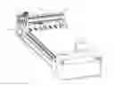
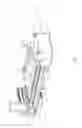
FIG. 1 is a perspective view of a component of the inventive assembly;
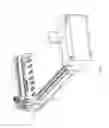
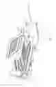
FIG. 2 is a perspective view of the machine and heating components of the assembly, illustrating the heating component in a spaced, non-operating condition;
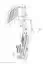
FIG. 3 is a perspective view of such assembly, illustrating the heating component having been displaced to a non-operating position adjacent the machine component;
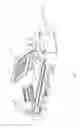
FIG. 4 is a perspective view of such assembly, illustrating the heating component in position for heating a thermally pliable foil having been positioned atop a workpiece disposed on the worktable of the machine component; and
FIG. 5 is a perspective view of such assembly, illustrating the heating component having been retracted.
DETAILED DESCRIPTION OF THE PREFERRED EMBODIMENT OF THE INVENTION
Referring to the drawings, there is illustrated an assembly 10 embodying the present invention including a CNC machine component 11 and a heating component 12. The machine includes a bed 13 provided with a porous worktable 14 mounted thereon, closing a chamber to which a vacuum may be applied by a vacuum pump mounted on the bed, a gantry 15 supported on the worktable, a carriage 16 mounted on the gantry and a tool holder 17 mounted on the carriage. The gantry includes a transversely disposed portion 15a spaced above the plane of the worktable and a set of depending leg portion 15b and 15c supported on and displaceable along a set of slides provided along the sides of the bed. The gantry is displaceable longitudinally or along the x-axis by means of a pair of threaded members journalled on the sides of the bed, threadedly connected to the leg portions thereof and driven by a set of servo motors. Carriage 16 is supported on a set of horizontal slides provided along a front face of transversely disposed gantry portion 15a, and is displaceable transversely or along the y-axis by means of a threaded member journalled in portion 15a, threaded in carriage 16 and driven by a servo motor. Similarly, tool holder 17 is mounted on a set of vertical slides provided along the front face of carriage 16, and is displaceable vertically or along the z-axis by means of a threaded member journalled in the carriage, threaded into the tool holder and driven by a servo motor. The several servo motors are controlled by a computer 20 suitably programmed and operable to operate and guide a selected tool 21 positioned and accessible on worktable 14 in the conventional manner.
As illustrated in various conditions in FIGS. 2 through 5, heating component 12 includes a carrier 30 supported on and displaceable along a set of spaced tracks 31 and 32, each provided with a v-shaped, cross-sectional configuration, disposed transversely relative to machine component 11 and projecting from a position spaced a short distance from machine component 11 to a position underlying thereof, and an enclosure 32. The carrier is provided with a pair of spaced beams 33 and 34 supported on a set of rollers 35 ridable on tracks 31 and 32, and an upright support frame 36 mounted on the outer distant ends of beams 33 and 34. Enclosure 32 comprises a pair of front and rear panels 37 and 38, a set of side panels 39 and 40 and a top panel 41, providing a lower opening. Rear panel 38 is provided with a set of rearwardly projecting portions 42 and 43 which are pivotally connected to the upper end of support frame 36 permitting the enclosure to pivot about an axis disposed parallel to the x-axis of the machine, between an upper position as shown in FIGS. 2 and 3 and a lower position in overlying contact with worktable 14, as shown in FIG. 4. The contact edges of enclosure 32 are provided with a gasket 44 about the perimeter of the enclosure, engageable with the worktable to seal the enclosure when in a downwardly pivoted position, and a pair of springs 45 and 46 interconnecting the free ends of projecting arms 42 and 43 to bias the enclosure as shown in FIG. 2. Disposed within enclosure 32 and mounted on the inner side of enclosure panel 41 is a set of electrically activated heating elements 47 which may be controlled by computer 20 or activated by an operator. The attachment of enclosure 32 to the support carriage and the arrangement and function of springs 45 and 46 are to bias the enclosure into the open or raised position as shown in FIGS. 2, 3 and 5, and allow it to be manually positioned on the worktable upon having been pivoted beyond a certain angle beyond the point of effect of the biasing action of the springs.
In the use of assembly as described to form one or more cabinet doors provided with a thermally pliant film, with carrier 30 spaced from the machine and the enclosure thereof in an upper or retracted position as shown in FIG. 2, and perhaps a porous spoil board having been positioned on and adhered to the worktable, a sheet of material perhaps consisting of a medium density fiberboard (MDF) is positioned on the spoil board, usually with the edges thereof abutting or suitably spaced from a set of peripherally spaced stops provided on the machine bed. With such workpiece thus positioned, the machine controls are operated pursuant to the inputed program to shape and contour one or more of the doors in the conventional manner. With the machining of the workpiece having been completed, the machined workpieces retained on the worktable and the scrap having been removed from the worktable, a thermally pliant foil provided with a thermally activated adhesive on the underside thereof is positioned atop the machined workpiece or workpieces disposed on the worktable.
With the machined workpiece or workpieces thus positioned on the worktable and the foil positioned atop thereof, the carriage is rolled by the operator from the spaced positioned as shown in FIG. 2 to the position adjacent the side of the machine worktable as shown in FIG. 3, and the enclosure is pivoted downwardly onto the worktable to encompass the machined workpiece or workpieces disposed therein with the foil placed thereon, as shown in FIG. 4. The operator then operates suitable controls to energize heating elements 47 of the enclosure to heat the overlying foil, causing it to deform over the workpiece or workpieces and become adhered thereto. The progress of the compliant action of the foil may be monitored by viewing the progress in the deformation of the foil through a window 48 provided in front panel 37 of the enclosure.
Upon completion of the application of the foil material as described, the enclosure may be retracted to its upper position as shown in FIG. 5 and the carriage may be retracted to its spaced position as shown in FIG. 2.
The laminated doors are then completed by operating the machine to sever and scrap the portions of excess foil. The finished doors may then be removed from the worktable of the machine, perhaps further finished and either stored for further usage or transferred to an assembly area for the production of cabinets utilizing such doors.
The assembly as described and the method of use thereof provides a means of simply, efficiently and economically producing either a low or high volume of laminated doors without incurring the expense of acquiring and operating a separate a thermo-foil vacuum press.
From the foregoing detailed description, it will be evident that there are a number of changes, adaptations and modifications of the present invention, which come within the province of those persons having ordinary skill in the art to which the aforementioned invention pertains. However, it is intended that all such variations not departing from the spirit of the invention be considered as within the scope thereof as limited solely by the appended claims.
Claims
I claim:1. An assembly for producing cabinet doors comprising:
a CNC machine provided with a porous worktable, means for positioning a workpiece thereon, means for applying a vacuum to said porous worktable for adhering said workpiece thereto and means for machining a workpiece adhered to said worktable; and
means for thermally deforming a thermally pliable foil to laminate a workpiece disposed on said worktable.
2. The assembly of claim 1 wherein said machine includes at least one tool functional to cut a predetermined pattern in said workpiece and a sutiably structured imputed program functional upon operation thereof to guide said tool along x, y and z axes in forming said pattern.
3. The assembly of claim 2 wherein said program is functional in guiding said tool in cutting said workpiece into several components, forming selected shapes and profiles thereon.
4. The assembly of claim 1 wherein said machine includes means for operating said means for thermally deforming said foil.
5. The assembly of claim 1 wherein said means for thermally deforming said foil is displaceable between a first position spaced from said worktable and a second position engageable with said worktable, encompassing said workpiece provided with said foil.
6. The assembly of claim 5 wherein said means for thermally deforming said foil is provided with at least one heating element.
7. The assembly of claim 5 wherein said means for thermally deforming said foil includes an enclosure provided with an opening with a peripheral rim engageable with said worktable when in said second position.
8. The assembly of claim 7 including at least one heating element disposed within said enclosure, and wherein said peripheral rim is provided with a gasket enegageable with said worktable.
9. The assembly of claim 8 wherein said heating element is electrical.
10. The assembly of claim 5 wherein said means for thermally deforming said foil is supported for pivotal movement between said first and second position.
11. The assembly of claim 1 wherein said means for thermally deforming said foil is displaceable transversely relative to said worktable of said machine between remote and adjacent positions relative to said worktable, and displaceable pivotally about an axis disposed parallel to a longitudinal axis of said machine, between an open position spaced from the plane of said worktable and a closed position engaging said plane of said worktable when in said adjacent position.
12. The assembly of claim 11 wherein said means for thermally deforming said foil is provided with at least one heating element.
13. The assembly of claim 11 wherein said means for thermally deforming said foil includes an enclosure provided with an opening with a peripheral rim engageable with said worktable when in said closed position.
14. The assembly of claim 13 including at least one heating element disposed wihin said enclosure, and wherein said peripheral rim is provided with a gasket engageable with said worktable.
15. The assembly of claim 11 wherein said means for thermally deforming said foil includes a support structure provided with a set of rollers displaceable along a pair of transversely disposed tracks.
16. A method of producing cabinet doors comprising:
positioning at least one workpiece on the worktable of a CNC machine progammed to perform a selected cutting pattern on said workpiece;
operating said machine to perform said cutting pattern on said positioned workpiece;
positioning a thermally deformable foil over said workpiece;
positioning an enclosure containing a heating element therein with a peripheral rim of an opening therein seated on said worktable encompassing said workpiece disposed theron;
energizing said heating element to cause said foil to deform and laminate the exposed configuration of said workpiece;
displacing said enclosure from said worktable;
and operating said machine to sever excess foil beyond the base perimeter of said workpiece.
17. The method of claim 16 including applying an adhesive substance on one of said foil and said workplaces.
18. The method of claim 16 including maintaining said enclosure in an inoperative mode, disposed in an upwardly pivoted position of a support carriage, at a short distance from said worktable, displacing said carriage adjacent said worktable upon having positioned said thermally deformable foil on said workpiece and pivoting said enclosure into an operative mode onto said worktable encompassing said foil and workplace.
19. The method of claim 18 including manually displacing said enclosure between said inoperative and operative modes.
20. The method of claim 19 including displacing said support carriage provided with a set of rollers along a set of tracks disposed adjacent and transversely relative to said machine.
Images & Drawings included:
Sources:
- United States Patent and Trademark Office - verify current appl. status at the USPTO↗
Similar patent applications:
- » 20170146103
Slider Driving Mechanism on a CNC Assembly Machine for Assembled Camshaft - » 20050141975
Toolhead assembly for CNC machines having misalignment prevention means - » 17886644
Intelligent display assembly for CNC machine - » 20230154346
Assembly and method for training operators on a CNC machining device, production assembly comprising such a training assembly - » 20190366446
Tooling assemblies for lathe machines, CNC threading lathes, and methods of milling threads in tubular workpieces - » 20210299809
Assembly comprising a CNC machining system and an augmented reality display device - » 20230241688
TOOLING ASSEMBLIES FOR LATHE MACHINES, CNC THREADING LATHES, AND METHODS OF MILLING THREADS IN TUBULAR WORKPIECES - » 20130340588
PUNCH ASSEMBLY OF CNC PUNCH PRESS MACHINE - » 20080135418
Adaptive spindle assembly for electroerosion machining on a CNC machine tool
Recent applications in this class:
- » 20250228366 2025-07-17
Kit for the installation of a first and a second recessed appliance - » 20250221529 2025-07-10
FLEXIBLE FURNITURE SCREEN - » 20240423368 2024-12-26
Organizer wall panel assembly and mounting assembly - » 20240023709 2024-01-25
DOOR FOR PIECE OF FURNITURE AND PIECE OF FURNITURE - » 20230301431 2023-09-28
MODULAR COMPONENT ASSEMBLY - » 20230301430 2023-09-28
Baffle structure, with a variable position installed on the cabinet, and a cabinet containing a baffle structure - » 20230292921 2023-09-21
SHELF SPINE SYSTEM - » 20230248149 2023-08-10
CABINET ENCLOSURE AND CABINET DOOR WITH EXPANSION GAPS AND RELATED METHODS - » 20230225510 2023-07-20
Blow-molded unitary structure with enhanced strength - » 20230225509 2023-07-20
DAMAGE-FREE REMOVABLE AND INTERCHANGEABLE CABINET ACCESSORY
Recent applications for this Assignee:
- » 20250229462 2025-07-17
METHOD OF CONSTRUCTING A METAL MOLD - » 20250196216 2025-06-19
METHODS AND SYSTEMS FOR SECURE CONNECTIONS IN LAYER SEGMENTS OF CUT LAYER ADDITIVE PARTS - » 20250162250 2025-05-22
METHODS AND APPARATUS FOR PROCESSING AND DISPENSING MATERIAL DURING ADDITIVE MANUFACTURING - » 20250162240 2025-05-22
NEAR NET SHAPE ADDITIVE MANUFACTURING SYSTEM - » 20250162239 2025-05-22
NEAR NET SHAPE ADDITIVE MANUFACTURING SYSTEM - » 20250162238 2025-05-22
NEAR NET SHAPE ADDITIVE MANUFACTURING SYSTEM - » 20250153432 2025-05-15
SYSTEMS AND METHODS FOR PRINTING COMPONENTS USING ADDITIVE MANUFACTURING - » 20250153422 2025-05-15
APPARATUS AND METHODS FOR FABRICATING COMPONENTS - » 20250153412 2025-05-15
MACHINE AND METHOD FOR FORMING ARTICLES - » 20250144849 2025-05-08
METHOD AND SYSTEM FOR CREATING ADDITIVE PARTS