First improvement of wave activated power generation system with the rack and pinion mechanism
US20160177910A1
2016-06-23
14/909,151
2013-12-21
✅ Patent granted
US 9,810,194 B2
2017-11-07
WO; PCT/IB2013/002851; 20131221
WO; WO2015/015245; 20150205
Jorge Leon, Jr.
Juan Carlos A Marquez | Marquez IP Law Office, PLLC
2034-03-21
Abstract:
The present invention is directed to a wave activated power generating device that incorporates a support frame; a buoy vertically positioned to rise and fall relative to motion of waves impacting the buoy and the support frame, the buoy being formed with a hollow interior space; a rack and pinion structure operatively connected between the buoy and the support frame such that a pinion element of the rack and pinion structure generates rotating torque by moving along the rack element in response to the buoy rising and falling by the wave motion; and a power generator unit operative connected to the rack and pinion structure to generate electricity in response to rotating torque generated by the pinion element. The rack structure is fixedly connected to at least one vertical surface inside the hollow interior space of the buoy. The pinion element is fixedly mounted on the support frame to extend into the hollow interior space of the buoy and operatively positioned to movably interconnect with the rack structure as the buoy rises and falls.
Applicant:
Interested in similar patents?
Get notified when new applications in this technology area are published.
Classification:
F03B11/02 » CPC further
Parts or details not provided for in, or of interest apart from, the preceding groups e.g. wear-protection couplings, between turbine and generator , Casings
F03B13/16 » CPC further
Adaptations of machines or engines for special use; Combinations of machines or engines with driving or driven apparatus ; Power stations or aggregates characterised by using wave or tide energy using wave energy using the relative movement between a wave-operated member, and another member,
F03B13/10 » CPC main
Adaptations of machines or engines for special use; Combinations of machines or engines with driving or driven apparatus ; Power stations or aggregates Submerged units incorporating electric generators or motors
F05B2240/95 » CPC further
Components; Mounting on supporting structures or systems offshore
F03B13/186 » CPC further
Adaptations of machines or engines for special use; Combinations of machines or engines with driving or driven apparatus ; Power stations or aggregates characterised by using wave or tide energy using wave energy using the relative movement between a wave-operated member, and another member, where the other member, i.e. rem is fixed, at least at one point, with respect to the sea bed or shore and the wom slides relative to the rem where the connection between wom and conversion system takes tension and compression the connection being of the rack-and-pinion type
F05B2260/30 » CPC further
Function Retaining components in desired mutual position
F03B13/18 IPC
Adaptations of machines or engines for special use; Combinations of machines or engines with driving or driven apparatus ; Power stations or aggregates characterised by using wave or tide energy using wave energy using the relative movement between a wave-operated member, and another member, where the other member, i.e. rem is fixed, at least at one point, with respect to the sea bed or shore
F03B13/22 » CPC further
Adaptations of machines or engines for special use; Combinations of machines or engines with driving or driven apparatus ; Power stations or aggregates characterised by using wave or tide energy using wave energy using the flow of water resulting from wave movements to drive a motor or turbine
Description
CROSS-REFERENCE TO RELATED APPLICATIONS
This application claims the benefit of PCT Application No. PCT/IB2013/002851, filed on Dec. 21, 2013, which claims the benefit of PCT Application No. PCT/IB2013/001693, filed on Aug. 1, 2013, which is hereby incorporated by reference for all purposes as if fully set forth herein.
BACKGROUND OF THE INVENTION
1. Field of the Invention
The first improvement is concerned with wave activated power generation system with the rack & pinion mechanism, in which concrete structures of power generation buoy and power generation unit is shown.
2. Description of the Prior Art
U.S. patent application Ser. No. 13/413,839 shows the usage of wave power energy for generating electric energy. It is wonderful as the theory. However, when the device is actually made, it has some faults.
3. Problems that Invention is Solving
The first fault of U.S. patent application Ser. No. 13/413,839 is as follows:
-
- (A) It is undesirable that rack & pinion system is exposed directly to seawater.
- (B) Certainly, the power generation buoy manufactured from fiber-reinforced plastic material is excellent in a causticity and structural strength. However, the rack & pinion system is installed outside surface of the power generation buoy because the inside of the power generation buoy has been buried by the FRP structure in U.S. patent application Ser. No. 13/413,839. In this case, rack & pinion system will be exposed directly to seawater.
- (C) The power generation buoy need not be manufactured from fiber-reinforced plastic material necessarily.
- (D)
The second fault of U.S. patent application Ser. No. 13/413,839 is as follows:
-
- (A) The power generation buoy is restricted with guide roller and slide frame. The guide roller is attached to the shroud assembly of power generation unit and the slide frame is installed to the power generation buoy.
- (B) This structure is excellent in the point that the worker is not to come in contact with power generation buoy. However, The adjustment of space between the Guide roller and the slide frame is difficult, because the power generation buoy is shaken to right and left by waves of the sea. And, it is enough to prevent the worker from coming in contact with the power generation buoy by placing the fence.
The third fault of U.S. patent application Ser. No. 13/413,839 is as follows:
-
- (A) The most difficult problem in rack & pinion method is to keep constant the distance between the rack gear and the pinion gear.
- (B) The rack gear is attached to the power generation buoy, and the pinion gear is installed to the power generation unit. The power generation buoy and the power generation unit are independent. The power generation buoy freely moves up and down inside of the power generation unit and is always shaken to right and left by waves of the sea.
- (C) The condition of guide roller and slide frame is only contact. They are not fixed. Therefore the position of rack gear and pinion gear always vibrates.
- (D) The combination of the rack gear and the pinion gear cannot meet each other, if some device is not done.
The fourth fault of U.S. patent application Ser. No. 13/413,839 is as follows:
-
- (A) The mechanical stopper for the power generation buoy is not shown in it.
- (B) The wave height of the ocean has the possibility to exceed the length of the rack gear. When the wave height exceeds the length of the rack gear, it is necessary to stop the power generation buoy mechanically.
The fifth fault of U.S. patent application Ser. No. 13/413,839 is optional:
-
- (A) In U.S. patent application Ser. No. 13/413,839, the control theory has recovered the potential energy of the power generation buoy by adjusting the load of the generator to zero.
- (B) The cutting device is necessary to adjust the load to zero instantaneously. It is thought that the electromagnetic clutch is necessary.
SUMMARY OF THE INVENTION
For improving these problems, the processing technology and concept are described. It is undesirable that rack & pinion system is exposed directly to seawater
-
- (A) When the rack & pinion system can be placed inside of the power generation buoy, the gear system will not be exposed to seawater. To put the gear system in the power generation buoy, the power generation buoy should have vacant space in the power generation buoy.
- (B) A vacant power generation buoy is inferior to structural strength. It is necessary to reinforce the power generation buoy structurally. It is preferable that the power generation buoy is composed of the surface material of stainless steel and the frame of the steel material. Of course, FRP is acceptable.
It is difficult to adjust the distance between the guide roller and the slide frame, because the power generation buoy is shaken to right and left by waves of the sea.
-
- (A) The power generation buoy is restricted with guide roller and slide frame.
- (B) It is necessary to control the engagement distance of the rack gear and the pinion gear by the unit of the millimeter. However, it is impossible to control the movement of the power generation buoy by the unit of the millimeter.
- (C) When we give up the impossible control, the structure becomes simple. The movement of the power generation buoy cannot be controlled in precision. The structure becomes simple when the guide roller is attached on the surface of power generation buoy.
- (D) The power generation buoy is enclosed with the fence because of worker's safety.
The most difficult problem in rack & pinion method is to keep constant the distance between the rack gear and the pinion gear
-
- (A) it is necessary to control the engagement distance of the rack gear and the pinion gear by the unit of the millimeter. Otherwise, the rack gear and pinion gear will come off. However, it is impossible to control the movement of the power generation buoy by the unit of the millimeter. So, it is impossible to control the movement of the rack gear by the unit of millimeter because the rack gear is attached to the power generation buoy.
- (B) When the pinion gear is fixed, it is inevitable that the rack gear and the pinion gear come off. Therefore, the pinion gear should vary its position according to the movement of the rack gear. However, the pinion gear is not floating in the air. The pinion gear must be fixed to the power generation unit. Otherwise, it falls down.
- (C) Fortunately, because the movement of the power generation buoy is restrained with the guide roller and the slide frame, the vibration of the rack gear is not large. Therefore, the blurring of the center axis of pinion gear is not large either.
- (D) If the pinion gear is fixed to loose fit type, the vibration of the axis center of the pinion gear will be controllable. However, the rotation axis connected with the Generator must be supported firmly.
- (E) We connected the pinion gear axis to the axis of Generator with universal joint. This method is effective.
The mechanical stopper for the power generation buoy is as follows:
-
- (A) The wave height of the ocean has the possibility to exceed the length of the rack gear. When the wave height exceeds the length of the rack gear, it is necessary to stop the power generation buoy. There are several methods for stopping the power generation buoy. Mechanical stopper is most reliable.
- (B) The power generation buoy moves up and down inside of the space surrounded by the slide frames of the power generation unit. The movement of the power generation buoy is limited in this space. Therefore, the lower end stopper of power generation buoy is placed at the bottom of the slide frame so that the power generation buoy should not fall down anymore. It is necessary to note the assembly procedure because the power generation buoy does not enter when the lower end stopper is previously built in.
- (C) The upper end stopper is clever a little more. The inside of the power generation buoy in this invention is vacant. It is effective to stop the power generation buoy using the inside bottom surface of power generation buoy.
- (D) The pinion system is placed to the frame of the power generation unit. The frame of the power generation unit has come into the power generation buoy because the pinion system is inside of the power generation buoy. The bottom surface of the power generation buoy rises when the power generation buoy rises because of the wave. The position of the frame of the power generation unit to which the pinion system has attached is fixation. The rise of the power generation buoy is stopped with the frame of the power generation unit.
- (E) The position of upper end stopper and lower end stopper is decided by the length of rack gear and the position of pinion gear.
In U.S. patent application Ser. No. 13/413,839, the control theory has recovered the potential energy of the power generation buoy by adjusting the load of the Generator to zero.
-
- (A) The cutting device is necessary to adjust the load to zero instantaneously. It is thought that the electromagnetic clutch is necessary.
- (B) The output of the Generator is a load of the power generation buoy. The alternating-current generator can adjust the output of the Generator to zero by adjusting the field current to zero. However, it is uncertain whether to be able to adjust the load of the Generator to zero only by controlling the field current.
- (C) When the electromagnetic clutch is put on the upstream of the Generator, the load of the Generator mechanically becomes zero.
BRIEF DESCRIPTION OF THE DRAWINGS
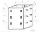
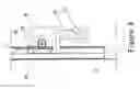
FIG. 1 shows a power generation buoy assembly using the references of (1) Side surface, (2) Bottom surface, (3) Buoy frame, (4) Guide roller, and (5) Rack gear.
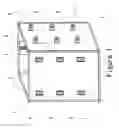
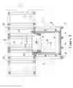
FIG. 2 shows a figure where power generation buoy assembly is seen right above using the references of (5) Side surface, (6) Bottom surface, (7) Buoy frame, (8) Guide roller, and (9) Rack gear.
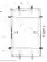
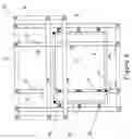
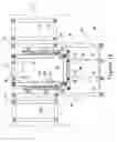
FIG. 3 shows a figure where power generation buoy assembly and power generation unit is seen right above using the references of (10) Side surface, (11) Buoy frame, (12) Guide roller, (13) Rack gear, (14) Slide frame, (15) Unit frame, (16) Reinforcement plate, and Fence (21).
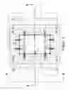
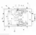
FIG. 4 shows a figure where power generation buoy assembly and power generation unit is seen from arrow view of A-A in FIG. 3 using the references of (18) Side surface, (19) Bottom surface, (20) Guide roller, (22) Slide frame, (23) Unit frame, and (24) Lower end stopper.
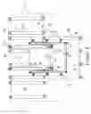
FIG. 5 shows a figure where power generation buoy assembly and power generation unit is seen from arrow view of B-B in FIG. 3 using the references of (26) Side surface, (27) Bottom surface, (28) Buoy frame, (29) Rack gear, (30) Pinion gear, (31) Gear box, (32) Damper, (33) Guide roller, (34) Pinion system support frame, (35) Slide frame, (36) Unit frame, and (37) Lower end stopper.
FIG. 6 shows a shape of rack gear using the references of (38) Rack teeth, (39) Rack web, (40) Rack ditch, (120) Rack flange, and (121) Slide bearing.
FIG. 7 shows a figure where rack & pinion system is seen right above using the references of (41) Side surface, (42) Rack gear, (43) Pinion gear, (44) Slide bearing, (45) Pinion axis, (46) Gear box, (47) Axis bearing, (48) Damper, (49) Universal joint, and (50) Generator axis.
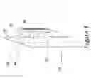
FIG. 8 shows a figure where rack & pinion system is seen in front chart using the references of (51) Side surface, (52) Rack gear, (53) Pinion gear, (54) Slide bearing, (55) Gear box, (56) Damper, and (57) Pinion system support frame.
FIG. 9 shows a figure that power generation buoy assembly stops at the lower end stopper using the references of (58) Power generation buoy assembly, (59) Bottom surface, (60) Lower end stopper, (61) Unit frame, (62) Slide frame, (63) Pinion system support frame, (130) Rack gear, (131) Pinion gear, (132) Gearbox, and (133) Damper.
FIG. 10 shows a figure that power generation buoy assembly stops at the upper end stopper (Pinion support frame) using the references of (64) Power generation buoy assembly, (65) Buoy frame, (66) Lower end stopper, (67) Unit frame, (68) Slide frame, (69) Pinion system support frame, (134) Rack gear, (135) Pinion gear, (136) Gearbox, and (137) Damper.
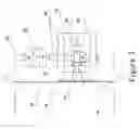
FIG. 11 shows a figure of power generation system placed in the power generation buoy using the references of (70) Power generation buoy assembly, (71) Rack gear, (72) Pinion gear, (73) Slide bearing, (74) Gearbox, (75) Universal joint, (76) Relay gearbox, (77) Electromagnetic clutch, (78) Generator, (79) Power generation device support board, (80) Pinion system support frame, and Guide roller (81).
DESCRIPTION OF THE PREFERRED EMBODIMENT
Referring to the drawing as follows, it explains the form of concrete execution of the manufacturing process of power generation unit and explains improved wave activated power generation system by rack & pinion mechanism.
FIG. 1 shows a power generation buoy assembly. The Side surface (1) and Bottom surface (2) form the power generation buoy. Rack gear (5) is installed on the inside surface of the power generation buoy, and several Guide roller (4) are attached on the outside surface of the buoy. The power generation buoy has vacant space inside it. The power generation buoy is reinforced with the Buoy frame (3).
FIG. 2 shows a figure where power generation buoy assembly is seen right above. The Side surface (5) and Bottom surface (6) form the power generation buoy. A pair of Rack gear (9) are installed on the inside surface of the power generation buoy, and several Guide roller (8) are attached on the outside surface of the buoy. Each Guide roller shown FIG. 2 has the row of Guide roller from the buoy top to the buoy bottom. The power generation buoy has vacant space inside it. The power generation buoy is reinforced with the Buoy frame (7).
Four corner type and circle type are acceptable for the shape of the power generation buoy. The most important element of the power generation buoy is watertight and structural strength. To satisfy them, a light material is filled to the entire power generation buoy. However, when the power generation buoy is filled with a light material, the rack and pinion gear is placed outside of the buoy. The outside of the buoy is seawater, so the rack gear and pinion gear are exposed directly to seawater. When the rack & pinion is exposed to seawater, the entire power generation system will be exposed to seawater. Durability of power generation system becomes a problem.
It is undesirable that rack & pinion system is exposed directly to seawater
-
- (A) When the rack & pinion gear system is placed inside the power generation buoy, the system is not exposed to seawater. To place the gear system in the power generation buoy, the power generation buoy should have vacant space in it.
- (B) A vacant power generation buoy is inferior to structural strength. It is necessary to reinforce the power generation buoy structurally. It is preferable that the power generation buoy is composed of the surface material of stainless steel and the frame of the steel material. Of course, FRP is acceptable.
FIG. 3 shows a figure that power generation buoy assembly and power generation unit is seen right above. Side surface (10) of power generation buoy is reinforced by Buoy frame (11). A pair of Rack gear (13) is installed inside the power generation buoy. Two or more Guide roller (13) are installed on all Side surfaces (10) of the outside of the power generation buoy assembly. Each Guide roller shown FIG. 3 has a row of Guide rollers from the buoy top to the buoy bottom. The Guide roller (13) has come in contact with Slide frame (14). The number of the Slide frame (14) corresponds to the number of Guide roller rows (13). The Slide frames (14) are installed in the power generation unit. Slide frames (14) are structure frames of the power generation unit. Power generation unit is made of many Unit frames (15). Unit frames (15) are reinforced by Reinforcement plate (16). The power generation unit is surrounded by Fence (21).
The vacant power generation buoy assembly does not have the rigidity. Therefore, the wall vibrates by the power of the wave. It is necessary to reinforce the side surface of power generation buoy by the frames. As the compensation, the rack and pinion gear can be installed inside the power generation buoy.
By the FIG. 3, it is understood how the power generation buoy moves in the power generation unit. Basically, the power generation unit and the power generation buoy assembly are independent. They have only come in contact with the guide rollers and the slide frames.
FIG. 4 shows a figure where power generation buoy assembly and power generation unit is seen from arrow view of A-A in FIG. 3. Side surface (18) and Bottom surface (19) form the power generation buoy with watertight. Two or more Guide roller (20) are installed on all Side surfaces (18) of the outside of the power generation buoy assembly. Every row of Guide roller (20) is placed from the buoy top to the buoy bottom. The Guide roller (20) has come in contact with Slide frame (22). The Slide frames (22) are installed in the power generation unit. Slide frames (22) are structure frames of the power generation unit. Power generation unit is made of many Unit frames (23). Two or more Lower end stopper (24) are attached on the bottom frame of the power generation unit.
By the FIG. 4, it is understood how the power generation buoy moves in the power generation unit. Basically, the power generation unit and the power generation buoy assembly are independent. Power generation buoy assembly moves up and down in power generation unit. They have only come in contact with guide roller and slide frames. Every movement is restricted with the guide roller and the slide frame, excluding the vertical movement.
The movement of the power generation buoy is mechanically stopped by the lower end stoppers. The power generation buoy does not drop off from the power generation unit. FIG. 5 shows a figure where power generation buoy assembly and power generation unit is seen from arrow view of B-B in FIG. 3. Side surface (26) and Bottom surface (27) form power generation buoy with watertight. The power generation buoy is reinforced by Buoy frame (28). Rack gear (29) is installed on the surface of the inside of the power generation buoy. The Rack gear (29) is installed on the two side surfaces of power generation buoy. Pinion gear (30) and Gear box (31) and Damper (32) are attached to Pinion system support frame (34). The Pinion system support frame (34) is connected to Unit frame (36). The Pinion gear (30) and the Gear box (31) and the Damper (32) are placed on the two side of power generation buoy, corresponding to the Rack gear (29). Two or more Guide roller (33) are installed on all Side surfaces (26) of the outside of the power generation buoy assembly. Every row of Guide roller (33) is placed from the buoy top to the buoy bottom. Guide roller (33) has come in contact with Slide frame (35). The Slide frames (35) are installed in the power generation unit. Power generation unit is made of many Unit frames (36). Lower end stopper (37) is attached on the bottom frame of the power generation unit.
By the FIG. 5, it is understood how the rack and pinion gear system is placed in the power generation buoy. When a big vacant space is produced inside of the power generation buoy, rack & pinion system can be put in the power generation buoy. Structural strength of the power generation buoy weakens as the compensation. The power generation buoy without strength always vibrates by the sea wave. Basically, the power generation unit and the power generation buoy assembly are independent. They have only come in contact with the Guide roller and the slide frames. The rack gear and the pinion gear mutually have suitable combination position. It is difficult to keep the position of the rack gear and the pinion gear to be constant, when they are independent.
It is difficult to keep constant the distance between the Guide roller and the slide frame, because the power generation buoy is shaken to right and left by waves of the sea.
-
- (A) The power generation buoy is restricted with guide roller and slide frame.
- (B) The rack gear and the pinion gear mutually have suitable combination position. It is necessary to control the engagement distance of the rack gear and the pinion gear by the unit of the millimeter. However, it is impossible to control the movement of the power generation buoy by the unit of the millimeter.
- (C) When we give up the impossible control, the structure becomes simple. The movement of the power generation buoy cannot be controlled in precision.
- (D) The structure becomes simple when the guide rollers are attached on the surface of power generation buoy.
- (E) The power generation buoy is enclosed with the fence because of worker's safety.
FIG. 6 shows a shape of rack gear. The rack gear has special shape because the shape of rack gear is key for making it sure that the engagement of the rack gear and the pinion gear keep constant. The rack gear is composed of Rack teeth (38), Rack web (39), Rack ditch (40), and Rack flange (120). The Rack teeth (38) is teeth of gear. The Rack web (39) is the web of gear. The Rack flange (120) is support flange of gear. The Rack ditch (40) is a ditch where Slide bearing (121) does the slide. The Slide bearing (121) is made from the metal that contains oil.
The Slide bearing (121) moves up and down in the Rack ditch (40). When the rack gear assembly vibrates to right or left, the Slide bearing (121) follows the movement of the rack gear assembly.
FIG. 7 shows a figure where rack & pinion system is seen right above. Rack gear (42) is fixed to Side surface (41) of the power generation buoy. Ditch has been cut in the web of the Rack gear (42). A pair of Slide bearing (44) is placed with narrow clearance in the ditch. The pair of Slide bearing (44) pinches the web of the rack gear. The pair of Slide bearing (44) is fixed to Gearbox (46) by bolts. The bolts are not shown in FIG. 7. Pinion gear (43), Pinion axis (45), and Axis bearing (47) are placed in the Gearbox (46). The Pinion gear (43) rotates in the Gearbox (46). The Pinion axis (45) is connected with Generator axis (50) through Universal joint (49). The Gearbox (46) is attached to Damper (48). The Damper (48) is fixed to pinion system support frame. The pinion system support frame is not shown in FIG. 7.
The Pinion gear (43) and the Rack gear (42) have come in contact by combination. The Pinion gear (43) is supported with the Gearbox (46) and rotates in the Gearbox (46). The Slide bearing (44) is fixed to the Gearbox (46) with bolts. A pair of Slide bearing (44) pinches the Rack gear (42) with narrow clearance. Therefore, the position of the Rack gear (42) and the Pinion gear (43) is kept constant. The vibration of the Rack gear (42) is transmitted to the Pinion gear (43). However, the vibration of the Pinion axis (45) is not transmitted to the Generator axis (50), because the Pinion axis (45) and the Generator axis (50) are united by the Universal joint (49).
FIG. 8 shows a figure where rack & pinion system is seen in front chart. Rack gear (52) is fixed to Side surface (51) of the power generation buoy. Ditch has been cut in the web of the Rack gear (51). Slide bearing (54) is placed with narrow clearance in the ditch. The Slide bearing (54) is fixed to Gearbox (55). Pinion gear (53) is installed to the Gearbox (55) and rotates in the Gearbox (55). The Gearbox (55) is attached to Damper (56). The Damper (56) is fixed to Pinion system support frame (57).
The Pinion gear (53) and the Rack gear (52) have come in contact by combination. The Pinion gear (53) is supported with the Gearbox (55) and rotates in the Gearbox (55). The Slide bearing (54) is fixed to the Gearbox (55). Slide bearing (54) is placed in the Rack gear (52) with narrow clearance. The Slide bearing (54) moves up and down in the ditch of the Rack gear (52). Oppositely when the position of slide bearing is fixed, the rack gear moves up and down.
The Slide bearing (54) is fixed to the Gearbox (55). Pinion gear (53) is supported with the Gearbox (55). The position of the Rack gear (52) and the Pinion gear (54) is kept constant. However, when the Rack gear (52) vibrates to right and left, the Gearbox (55) also vibrates. If the Gearbox (55) is firmly installed in the Pinion system support frame (57), the Gearbox (55) will be broken. To avoid it, the Gearbox (55) is fixed to the Pinion system support frame (57) by the Damper (56). However, the Gearbox (55) fixed by the Damper (56) vibrates slightly. When the Gearbox (55) vibrates, pinion axis vibrates, too. So as not to transmit the vibration of pinion axis to generator axis, pinion axis and generator axis are connected by universal joint. Pinion axis, generator axis and universal joint are not shown in FIG. 8.
The most difficult problem in rack & pinion method is to keep constant the distance between the rack gear and the pinion gear
-
- (A) It is necessary to control the engagement of the rack gear and the pinion gear by the unit of the millimeter. Otherwise, the rack gear and pinion gear will come off.
- (B) However, it is impossible to control the movement of the power generation buoy by the unit of the millimeter. So, it is impossible to control the movement of the rack gear by the unit of millimeter because the rack gear is attached to the power generation buoy.
- (C) If the pinion gear is fixed, it is inevitable that the rack gear and the pinion gear come off. Therefore, the pinion gear should vary its position according to the movement of the rack gear.
- (D) However, the pinion gear is not floating in the air. The pinion gear must be fixed to the power generation unit. Otherwise, it falls down.
- (E) Fortunately, because the movement of the power generation buoy is restrained with the Guide roller and the slide frame, the vibration of the rack gear is not large. Therefore, the movement of the center axis of the pinion gear is not large either.
- (F) If the pinion gear is fixed to loose fit type, the vibration of the axis center of the pinion gear will be controllable. However, the rotation axis connected with the generator must be supported firmly.
- (G) The pinion gear axis is connected to the generator axis with universal joint. This method is effective.
FIG. 9 shows a figure that power generation buoy assembly stops at the lower end stopper. Power generation buoy assembly (58) moves up and down in the power generation unit along Slide frame (62). Bottom surface (59) is the bottom of the Power generation buoy assembly (58). The power generation unit is manufactured from a lot of Unit frame (61). Lower end stopper (60) is attached at the bottom frame of the power generation unit. Pinion system support frame (63) is inside the Power generation buoy assembly (58). The Pinion support frame (63) is connected to the Unit frame (61) that composes the power generation unit. The Rack gear (130) is installed on the two side surfaces of Power generation buoy assembly (58). Pinion gear (131) and Gearbox (132) and Damper (133) are attached to Pinion system support frame (63). The Pinion system support frame (63) is connected to Unit frame (61).
When the Power generation buoy assembly (58) descends in power generation unit, the Bottom surface (59) of the Power generation buoy assembly (58) approaches the Lower end stopper (60). The Power generation buoy assembly (58) is stopped mechanically when the Bottom surface (59) comes in contact with the Lower end stopper (60). It is necessary to note the assembly procedure because the power generation buoy does not enter when the lower end stopper is previously built in.
The position of the Lower end stopper (60) is related to the length of the Rack gear (130) and the position of the Pinion gear (131). The length of the Rack gear (130) is related to the size of the wave of the sea.
FIG. 10 shows a figure that power generation buoy assembly stops at the upper end stopper. Power generation buoy assembly (64) moves up and down in the power generation unit along Slide frame (68). Buoy frame (65) is reinforcement frame of the Power generation buoy assembly (64). The power generation unit is manufactured from a lot of Unit frame (67). Lower end stopper (66) is attached at the bottom frame of the power generation unit. Pinion system support frame (69) is inside the Power generation buoy assembly (64). The Pinion system support frame (69) is connected to the Unit frame (67) that composes the power generation unit. The Pinion system support frame (69) is the upper end stop, concurrently. The Rack gear (134) is installed on the two side surfaces of Power generation buoy assembly (64). Pinion gear (135) and Gearbox (136) and Damper (137) are attached to Pinion system support frame (69). The Pinion system support frame (69) is connected to Unit frame (67).
When the Power generation buoy assembly (64) rises in power generation unit, the lower Buoy frame (65) of the Power generation buoy assembly (64) approaches the Pinion system support frame (69) connected to the Unit frame (67). The Power generation buoy assembly (64) is stopped mechanically when the lower Buoy frame (65) comes in contact with The Pinion system support frame (69). The Pinion system support frame (69) is the upper end stop, concurrently.
The position of the bottom frame of Pinion system support frame (69) is related to the length of the Rack gear (134) and the position of the Pinion gear (135). The length of the Rack gear (134) is related to the size of the wave of the sea.
The mechanical stopper for the power generation buoy is as follows:
-
- (A) The wave height of the ocean has the possibility to exceed the length of the rack gear. When the wave height exceeds the length of the rack gear, it is necessary to stop the power generation buoy. There are several methods for stopping the power generation buoy. Mechanical stoppers are most reliable.
- (B) The power generation buoy moves up and down inside of the space surrounded by the slide frames of the power generation unit. The movement of the power generation buoy is limited in this space.
- (C) Therefore, the lower end stopper of power generation buoy is placed at the bottom of the slide frame so that the power generation buoy should not fall down anymore. However, it is necessary to note the assembly procedure because the power generation buoy does not enter when the lower end stopper is previously built in.
- (D) The upper end stopper is clever a little more. The inside of the power generation buoy in this invention is vacant. It is effective to stop the power generation buoy using the inside bottom surface of power generation buoy.
- (E) The pinion system is connected to the frame of the power generation unit. The frame of the power generation unit has expanded into the power generation buoy because the pinion system is inside of the power generation buoy.
- (F) The bottom surface of the power generation buoy rises when the power generation buoy rises because of the wave. The position of the pinion gear is fixed. The rise of the power generation buoy is stopped by the pinion system support frame connected to the power generation unit.
- (G) The position of the upper end stopper and the lower end stopper are decided by the length of the rack gear and the position of pinion gear. The length of the Rack gear and the position of pinion gear are related to the size of the wave of the sea.
FIG. 11 shows a figure of power generation system that is placed in the power generation buoy. Several Guide rollers (81) are installed on all the side surface of Power generation buoy assembly (70). Rack gear (71) is installed on the side surface of Power generation buoy assembly (70). Pinion gear (72) and Gearbox (74) are attached to Pinion system support frame (80). Slide bearing (73) is fixed to Gearbox (74). The Pinion system support frame (80) is located inside the Power generation buoy assembly (70). The Output axis of the Gearbox (70) is connected to the input axis of Relay gearbox (76) by Universal joint (75). The Relay gearbox (76) is connected to Electromagnetic clutch (77). The Electro magnetic clutch (77) is connected to Generator (78). The Relay gearbox (76), the Electromagnetic clutch (77) and the Generator (78) are fixed on Power generation device support board (79). The Power generation device support board (79) is fixed to the Pinion system support frame (80).
The Pinion system support frame (80) is fixed to power generation unit frame. The Pinion system support frame (80) is located inside the Power generation buoy assembly (70). Therefore, The Power generation device support board (79) is in the Power generation buoy assembly (70). The power generation unit frame is not shown in FIG. 11. Power generation system is placed inside the power generation buoy. The waterproof of the power generation system become easy, because seawater does not wet the inside of the power generation buoy. The position of the Relay gearbox (76) and the Electromagnetic clutch (77) can be exchanged if there is installation space.
In U.S. patent application Ser. No. 13/413,839, the control theory has recovered the potential energy of the power generation buoy by adjusting the load of the generator to zero
-
- (A) The cutting device is necessary to make the load to zero instantaneously. The electromagnetic clutch is suitable.
- (B) Output of the generator is load for the power generation buoy. The alternating-current generator can adjust the output of the generator by adjusting the field current. However, it is uncertain whether to be able to adjust the load of the generator to zero only by controlling the field current.
- (C) When the electromagnetic clutch is put on the upstream of the generator, the load of the generator mechanically becomes zero.
It will be appreciated that modifications may be made in the present invention. A structural material is not the one limited to stainless steel. The power generation buoy with vacant space inside is inferior to structural strength. Naturally, it is necessary to consider FRP. Moreover, glass fiber FRP that is the material is not corroded with seawater. The guide roller can be substituted with the slide bearing plate.
The spirit of this invention is to prevent the power generation system from seawater. It is a big advantage to put the power generation system into the power generation buoy. However, structural strength of the power generation buoy becomes poor, and is also impossible to warrant the combination of the rack gear and the pinion gear. When the shape of rack gear is processed to special shape, it is warranted to match rack gear and pinion gear. The pinion gear follows to the change of the rack gear. Accordingly, it should be understood that we intend to cover by the appended claims all modifications falling within the true spirit and scope of our invention.
Claims
What is claimed is:1. A wave activated power generating device, comprising:
a support frame;
a buoy vertically positioned to rise and fall relative to motion of waves impacting the buoy and the support frame, the buoy being formed with a hollow interior space;
a rack and pinion structure operatively connected between the buoy and the support frame such that a pinion element of the rack and pinion structure generates rotating torque by moving along the rack element in response to the buoy rising and falling by the wave motion; and
a power generator unit operative connected to the rack and pinion structure to generate electricity in response to rotating torque generated by the pinion element, wherein
the rack structure is fixedly connected to at least one vertical surface inside the hollow interior space of the buoy,
the pinion element is fixedly mounted on the support frame to extend into the hollow interior space of the buoy and operatively positioned to movably interconnect with the rack structure as the buoy rises and falls.
2. A wave activated power generation device according to claim 1, further comprising:
a plurality of guide rollers fixedly attached to an exterior surface of the buoy and operatively positioned to movably interconnect with the support frame and guide the rising and falling of the buoy.
3. A wave activated power generation device according to claim 1, wherein
the support frame includes a lower mechanical stop structure, and
the buoy includes a bottom surface formed to contact with the lower mechanical stop structure of the support frame during the rising of the buoy so as to mechanically limit upward travel of the buoy.
4. A wave activated power generation device according to claim 1, wherein
the support frame includes an upper mechanical stop structure, and
the buoy includes an upper wall portion formed to contact with the upper mechanical stop structure of the support frame during the falling of the buoy so as to mechanically limit downward travel of the buoy.
5. A wave activated power generation device according to claim 2, wherein
the support frame includes a slide frame operatively positioned to interconnect with the plurality of guide rollers so as to guide the rising and falling of the buoy.
6. A wave activated power generation device according to claim 1, further comprising:
a plurality of slide bearing plates fixedly attached to an exterior surface of the buoy and operatively positioned to movably interconnect with the support frame and guide the rising and falling of the buoy.
7. A wave activated power generation device according to claim 6, wherein
the support frame includes a slide frame operatively positioned to interconnect with the plurality of slide bearing plates so as to guide the rising and falling of the buoy.
Images & Drawings included:
Sources:
- United States Patent and Trademark Office - verify current appl. status at the USPTO↗
Recent applications in this class:
- » 20250230789 2025-07-17
VERTICAL INTERMINGLING OF DEEP WATER - » 20250223939 2025-07-10
VERTICAL INTERMINGLING OF DEEP WATER - » 20250101940 2025-03-27
Buoyant power system method and apparatus - » 20250075677 2025-03-06
POWER GENERATION FROM MOVING WATER - » 20240401554 2024-12-05
Submerged Hydroelectric Generator System - » 20240344495 2024-10-17
Two-body variable geometry wave energy converter - » 20240318621 2024-09-26
SUBMERSIBLE POWER PLANT - » 20240263605 2024-08-08
System for generating electricity from an underwater ocean stream - » 20240200527 2024-06-20
UNDERWATER DUCTED HYDROELECTRIC POWER GENERATION SYSTEM - » 20240110539 2024-04-04
Power generation apparatus