OPERATING SYSTEM UTILIZING AN ARTICULATED BOLT TRAIN TO MANAGE RECOIL FORCE
US20160187082A1
2016-06-30
14/979,143
2015-12-22
Abstract:
An Operational System for Firearms founded on the use of the synchronic controlled motion and cooperative interaction of elements of a Pivotally Articulated Bolt Train displacing reciprocatingly within a compliant receiver, along guiding means, disposed according to a purposely engineered Path, capable of generating anticipated adjustable dynamic reactions, and to execute mechanical actions, due to pre-calculated movements of interconnecting mechanisms within said Train members, when they pivot one relative to the other. The alternate divergent and converging motion of the Train Bolt and A Firing Mechanism Carriage subassembly, along a horizontal path, and a transverse path, modifies and splits the linear bearing of the recoil force, and generates a Gyroscopic Effect or Angular Moment, decreasing the Barrel Torque magnitude, conveying a unique tailored dynamic behavior, while performing different functions and achieving the eleven different purposes of this invention. Numerous motion parameters are adjustable to attain the distinctive recoil Dynamic reaction.
Interested in similar patents?
Get notified when new applications in this technology area are published.
Classification:
F41A3/12 » CPC main
Breech mechanisms, e.g. locks Bolt action, i.e. the main breech opening movement being parallel to the barrel axis
F41A5/18 » CPC further
Mechanisms or systems operated by propellant charge energy for automatically opening the lock gas-operated
Description
CROSS-REFERENCE TO RELATED APPLICATIONS
This application is a Continuation-in-Part of co-pending U.S. patent application Ser. No. 13/385,262, filed on Feb. 2, 2012, which claims the benefit of Provisional Patent Application Ser. No. 61/463,034 filed on Feb. 11, 2011, now expired. The entirety of both the co-pending non-provisional and expired provisional applications are herein incorporated by reference.
FIELD OF THE INVENTION
This application relates generally to a firearm operational system improvement, describing an Articulated Bolt Train mechanism in which The Head Bolt moves linearly aligned with the axis of the barrel and the second train member, the Firing Mechanism Subassembly, may have a movement component perpendicular to the barrel axis in certain sectors of the Motion path when it changes the bearing, from horizontally aligned with the axis of the barrel, to a transverse, through the handle direction. This redirection of the path causes significant reaction forces over the guiding tracks inserted in the receiver, which induces a dynamic behavior, unique, predictable and manageable to the firearms utilizing this Operating System. The Physical Mechanic and Dynamic Forces resulting from the operation of firearms of this category are comprehended and manageable under the concepts of Newtonian Mechanics and Dynamics The identification of the parameters involved in the operation of the Articulated Bolt Train Operating System Makes it possible to select the proper values of such parameters to attain, to a certain extent, the desired recoil resultant.
BACKGROUND OF THE INVENTION
The enormous majority of auto loading firearms made in prior art are based on the pattern of reciprocating bolts (masses) displacing linearly using the inertia mass and a spring to absorb the energy of the reaction force produced in response to the firing of a cartridge. Some mechanisms have used toggle articulated links to create enough space, for the bolt, to travel enough to reach the rear part of a new cartridge, in a magazine, in the backwards motion, and reciprocate forward reloading a new cartridge in the chamber. The toggle mechanism articulates at least two pivoted links sideways, which produce a motion vector having a component perpendicular to the axis of the barrel while producing a different dynamic reaction. The Last link of the toggle array is pivotally grounded to the receiver, condition which limits the total travel of the bolt and delivers at the very beginning of the recoil motion, a considerable portion of the energy to the receiver.
Previously, in firearms, the use of articulated or toggled bolts and connecting masses to control recoil is very old. When recoiling, these types of mechanisms displace in a different direction of the barrel axis creating force vectors partially diverting the initial recoil force, away from the bore axis. In toggle mechanisms the last member of the articulated linkage is pivotally grounded to the receiver limiting the range of the head bolt to move in the horizontal direction towards the breech. The use of this principle is present in the first known auto loading pistol invented by Hugo Borchardt in the C-93 pistol (1893), and the same principle for displacing the bolt rearwards and the heavy connecting bars transversally to reduce the axial recoil is used by Georg Luger in (1898) in the well known P-08 model. Both, Borchardt and Luger, were following the even earlier design of Hiram Maxim incorporating the toggle lock or knee principle. Borchardt and Luger had an exterior articulating bolt fixedly hinged at the rear, but never before a completely movable Interior Articulated Bolt Train.
Several firearms recoil absorbing systems have been patented recently using similar principles that cause an inertia mass to move downwards or transversally by using the original recoil force, transforming it into two force vectors; Like patent U.S. Pat. No. 7,201,094 of Jan Henrik Jebsen. However, none of the previous patents uses the active firing mechanisms as part of the moving recoiling mass displacing transversally. Nor it uses an active recoil damper mechanism. It only moves inertia dead mass downwards.
In previous inventions like patent U.S. Pat. No. 7,201,094 the firearm head bolt is attached to an independent body or mass that contains no mechanisms inside. It is just dead mass. The two bodies are connected by series of linked interconnected parts, some of them requiring sufficient margin of play, like a slotted guide, placed at an inclined angle at the end of one of the bodies. A rod, belonging to the bolt, travels horizontally through a slotted guide. A rod placed transversally becomes the contact point between the bolt and the mass. As the bolt travels horizontally it pushes the rod through the inclined slotted guide causing the effect of a wedge by pushing the mass in a transverse direction. The oblique displacement of the dead inertia mass is forced by a transverse fixed guide bar passing through the mass. However the different means used to achieve the recoil absorption are significantly inefficient in terms of the volume and total weight required. None of the design solutions involve the use of firing mechanisms displacement or the use of the firing mechanisms mass as a part of the recoiling inertial mass. U.S. Pat. No. 7,201,094 of Jan Henrik Jebsen uses a complete conventional separate stationary fixed firing mechanism assembly, placed conveniently that necessitates significant volume and weight to operate. The latter mentioned patent does not have any sort of internal recoil abatement mechanisms inside the inertia mass as this invention has. It is notorious for being voluminous and unwieldy. It is voluminous with a very little barrel length. And furthermore, the array of mechanisms condemns the operation, in practical reality, to small pistol cartridges. With respect to the Delay Blowback breech opening function that this invention has, the U.S. Pat. No. 3,283,345 of Theodor Koch is important to mention because it has been extensively divulged and promoted by its use in the Heckler and Koch G3 rifles and especially in the very well known MP 5 sub machineguns. It causes a delay in the breech opening by means of a complicated mechanism inside the bolt whereby a set of sprig loaded rollers are forced to move along a pair of closing arc circle surfaces generating a retention of the force produced by the increasing gas pressure inside the barrel until the point where it overcomes the force of the rollers mechanism, generating a delay. The use of such mechanism has been successful, but has several disadvantages: it is sensitive to dirt, it requires lubrication, rollers break, springs fatigue, and does not lend to trimming.
Advantages of the Invention
The Operating System presented in this Patent application is notoriously different than any other known art. The present invention has at least one the following advantages.
For the first time, an Operating System utilizing a floating Articulated Bolt Train, including a Firing Mechanism subassembly is used to take advantage of the reaction forces that a Path bearing change causes, in benefit of engineering a desired effect in the final recoil behavior. The Articulated Bolt Train having a planar motion, and capable of continuously changing path of some train members, towards a transverse curved direction which generates important manageable reaction forces over the receiver.
-
- This invention integrates an Active Firing Mechanisms as a part of the recoiling Bolt Train and places it for all time in the immediate proximity to the firing pin.
- This invention is improved because the firing mechanisms are contained in a compact, volume-efficient, carriage that moves transversally along a by design predetermined path.
- This invention is superior because, when shooting, the firing mechanisms contained in a compact, volume-efficient, carriage moves downwards, through the handle or grip, producing a unique reaction movement of the receiver resulting in a balanced dynamic behavior.
- Conventionally, the Controlling Firing Mechanisms or Trigger Group and its frame are placed in a fixed dedicated location. This invention makes the Active Firing Mechanism movable and uses its mass as part of the Bolt Train 90 mass needed to absorb the recoil, saving volume, weight and lowering the center of gravity.
- The active firing mechanisms operate linearly without rotating parts inside a movable Carriage, which make it simple to manufacture and volume effective.
- The Controlling Firing Mechanisms subassembly 74 FIG. 5D is modular, easy to change if needed.
- A part, the Mechanisms Carriage Housing, has multiple functions. It frames the Active firing mechanisms; it guides the recoil travel; and it displaces transversally with the contained independent mechanisms in place. At the rear it may have a protruding cam that slides over the inclined plane face of the spring loaded, movable recoil compensator forcing it back, adding additional restrain to the opening of the breech. All that in a very dense compact package, making it efficient in terms of minimal volume.
- The Mechanisms Carriage Housing optionally has a rear protruding cam (40C) that works in conjunction with the Recoil Damper sub assembly to produce additional restriction to the rearwards motion, adding more delay to the breech opening.
- When the firing mechanisms sub assembly works in conjunction with the protruding delay cam of the Front Bolt 20, it creates a delay on the blowback opening motion without requiring any additional moving parts.
- The mechanisms carriage housing and mechanism can slide roll down through the firearm handgrip, making it very compact and volume efficient.
- The proximity of the compact Bolt Train to the top of the shooter′ grabbing first lowers the center of gravity of the weapon creating an improved handling.
- When the mechanisms carriage housing and mechanism slide roll down through the firearm handgrip, the effect of the downwards displacement is felt directly on the grip, eliminating any moments about the grabbing point.
- This novel mechanism can be used in many types of firearms; pistols; rifles, shotguns; machineguns; sub-machineguns; heavy machineguns; sniper rifles, grenade launchers, heavy weapons all the above semi automatic and full automatic, gas operated, long or short stroke, blowback, delayed blowback recoil, with rotary bolts and bolt carrier, electrical or mechanical firing.
- These mechanisms can be used in bullpup configuration.
- The front bolt can be used as a bolt carrier, enabling the use of rotary locking bolts.
- The bolt carrier can be used in conjunction with direct drive rods with gas operated bolts.
- Firearms using this type of bolt lend to be manufactured with polymer injected materials, which translates into low production costs.
- The progressive displacement downwards of the mechanisms carriage housing and mechanism provides a smooth transition of the reaction force.
- Rollers can be added to the guide rods to smooth the operation.
- Rollers can be adder to the hammer to smooth the operation.
- The design of this Operating System is outstanding because:to induce Dynamic reaction forces on the receiver, and Mechanically, it uses the train members interaction, occurring during train articulation to perform three functions 1) To cock the firing mechanisms, 2) To create a delay in the breech opening, and 3) To actuate a recoil damper mechanism.
- The incorporation of a delay blowback breech opening mechanism in the rearwards recoil motion, enhances the delivered energy of the projectile, and reduces the pressure at the breech when opening.
- The delay blowback breech opening system of this invention achieves the same results of H&K delay opening mechanism with a very simple interaction of two parts and lends to be trimmed by producing a desired controlling surface in the front face of the slider striking hammer.
- The delay opening mechanism slows the rate of fire when used in full automatic mode.
- This invention is far simpler and advantageous than the one of Jebsen because it only uses only one displaced articulation or hinge as the means of linkage between the front bolt and the mechanisms carriage housing. The movement required at the articulation is only rotational.
- No margin of play is required between the front bolt and the mechanisms carriage housing.
- This invention does not require any mobile breech to interlock the front bolt and the mechanisms carriage housing.
- This invention requires a smaller number of components in comparison to any other gun.
- This invention has a moving cylindrical extruded sear 58 housed inside the hammer and integrated to the movable Firing Mechanism sub assembly.
- Alternatively, this invention comprises a self sprigged sear-hammer FIG. 3B.
- When required, internal sears can be used to protrude laterally to outside of the Mechanism Carrier Housing 40 and 40B, and engage against it, to become operational with side mounted column spring or pushing bar 78A FIG. 5D of the controlling firing mechanisms.
- The Bolt Train 90 can be used in conjunction of Gas piston systems
- The bolt train 90 can be used in conjunction with rotary bolts.
- Optionally, when additional kinetic energy absorption is desired, a third component to the Bolt Train 90 can be attached: the Recoil Damper Subassembly of FIG. 4B and FIG. 4C.
- A transient Gyroscopic Effect or Angular Moment is generated in every shoot recoil motion by the angular motion of some of the train components, while transitioning from the bore axial path to the transverse path, in the curved zone of the path. This angular motion of the Firing Mechanism Carriage Subassembly is capable of compensating to some extent, the rotation reaction (Barrel Torque) effect of the barrel and Firearm.
SUMMARY OF THE INVENTION
Terms Definitions
Train is a series of pivotally linked carriages that move along a track in a reciprocating manner.
The terms Pivotally Articulated Bolt Train, Articulated Bolt, Bolt Train, Bolt Train sub assembly, Bolt Train Assembly, Bolt Train Mechanism, are used indistinctively.
The terms Front Bolt, Head Bolt, and Bolt refer to the first member of the Bolt Train. These terms may be used alternatively.
The terms Axial Force or axial recoil force refer to that one occurring in the direction of the axis of the barrel of the firearm or bore axis when the firearm is discharged.
The terms Carrier, Carriage, Carrier Housing, Mechanism Carriage Housing, refer to hollow, track mounted box, capable of containing and controlling mechanisms placed within, are used indistinctively.
The term forward direction is referred as the one having the direction of the projectile when fired.
The term rearward direction is the one opposite to forward or muzzle wards.
The term transverse is used to define a course oblique to the bore axis of the barrel.
The term Hammer is used to designate a moving part propelled linearly at the impulse of a spring. This can be also referred as a Striker, or slide striker hammer.
The terms Slot tracks guides, and Slot channel guides are used indistinctively.
The terms Charging handle and Cocking handle are used indistinctively.
The term Protruding Guides is used to refer to the protruding elements that run and slide into the Slot tracks guides.
The term Parameter a numerical or other measurable factor forming one of a set that defines a system or sets the conditions of its operation.
The term Jaws means two opposed hinged movable parts in a mechanical device.
The term System: is a set of interacting or interdependent component parts forming a complex/intricate whole.
The term “Operating System” is used to indicate in the field of the specific art, the entirety of mechanisms enabling, once a cartridge has been fired, the expulsion of the case of the fired cartridge and the loading of a new cartridge while generating innovative Dynamic reactions over the entire firearm.
SUMMARY
In accordance with one embodiment, this Operating System generally relates to a firearm having a collection of mechanisms and arrays, conceived to manage recoil by changing the dynamic behavior of the weapon when firing, in a manner that redirects forces, creates delays, decelerates motion, absorbs energy and lowers significantly the center of gravity, resulting in an improvement of the handling of the gun. All of the above is attained by the motion of a Track mounted Pivotally Articulated Bolt Train moving reciprocatingly along a pre calculated Path, engineered to change bearings, to induce premeditated Dynamic reactions, conceived to favor the recoil control.
Said firearm comprises several modular subassemblies, a Barrel, a receiver, an Articulated Bolt Train that alternates between a forward and backward position, an active firing mechanism, a delay blowback method, a controlling firing mechanism, a set of main recovery springs(38), a set off modular multifunctional supports, a buffer mechanism, a Modular Cocking Handle mechanism, a direct drive gas system. The alternate transversal displacement of the Articulated Bolt Train, and the intrinsic delay designs, conveys to the firearm a unique dynamic behavior resulting in smooth recoil. Many variable Parameters in the Operational System of the Articulated Bolt Train constitute a formidable opportunity for engineers to trim the design for each specific case of application.
My co-pending U.S. patent application Ser. No. 13/385,262 generally relates to a firearm having a collection of mechanisms and arrays, conceived to manage recoil by changing the dynamic behavior of the weapon when firing, in a manner that redirects forces, creates delays, decelerates motion, and lowers significantly the center of gravity, resulting in an improvement of the handling of the gun. Specially in one embodiment, this Operating System pertains to a firearm having an Articulated Bolt Train 90 FIG. 9 and FIG. 9A, FIG. 12 TO FIG. 12C and a by design Receiver 66 FIG. 10B, FIG. 11B, FIG. 12B, FIG. 12C that operates in conjunction. In order to function properly, the Bolt Train 90 has to be placed inside a Receiver (66) that controls and governs its path, and holds all the sub-assemblies in the convenient location allowing the synchronic movements of all the components to take place. The Receiver (66) FIG. 10 A, FIG. 20 can have different shapes, dimensions, and proportions to be used in several applications as shown in FIG. 18.
The Articulated Bolt Train 90 consists of a Front Bolt of either Types 20, 20A or 20B, as shown in FIG. 2B, initially moving along the bore axis, articulately linked at the rear to a Mechanism Carriage Housing 40 types 40 or 40B as shown in FIG. 4, FIG. 4A, FIG. 4B, containing The Active Firing Mechanisms. The Mechanism Carriage Housing 40 displaces transversally, articulately linked at the rear to another optional carriage displacing transversally also comprising a Recoil Damper Sub Assembly 64 FIG. 4B. The Articulated Train Bolt 90 is track mounted on slot Channel guides 80 FIG. 10A embedded or supported laterally inside the receiver 66, directing a transversal path. In this invention the conventional firing mechanisms assembly is separated physically in two different groups. The Active Firing Mechanisms subassembly 39 FIG. 5B comprise the hammer, the hammer spring, the sear, sear lever; all of them placed inside a moveable mechanisms carriage housing 40 and are an integral part of the Bolt Train 90. The controlling firing mechanisms subassembly 74 FIG. 5B, FIG. 5C comprise the trigger 75, the lever 76, the safe 77, the column spring fire actuator, and disengager 78 which are housed in a stationary compact small frame 79 in a convenient fixed location. The Fire Actuator and Disengager or disconnector 78A can be of a solid piece sustained by a convenient spring mounted support, enabling its deflection, after being pushed aside by the sear protrusion portion on the forward displacement after firing. Part 78, or alternatively part 78A, have al dual function: pushing the sear out of the engaging surface with the Mechanism Carriage Housing 40, and serving as disconnector for the semiautomatic firing mode.
The Active Firing Mechanisms subassembly 39 compact mechanism array integrates its mass and its volume to the Bolt Train 90 and significantly reduces the number of parts, volume, weight, and lowers the center of gravity, resulting in an effective recoil management absorbing system for automatic or semiautomatic firearms.
Name of the Components and Reference Numerals
DRAWING REFERENCE NUMBER
Part Number Part Name
- 20 BOLT
- 21 HORIZONTAL PROTRUDING GUIDE (2)
- 22 REAR RECTANGULAR PROTRUSION
- 22A EDGE LINE
- 22B PROTRUDING DELAY OPENING CAM
- 23 CYLINDRICAL CAVITY FOR THE FIRING PIN
- 24 TOP HINGE
- 25 HOLE FOR PIN
- 26 RECTANGULAR SLOT FOR EXTRACTOR
- 27 FRONTAL FACE
- 28 CYLINDRICAL DEPRESION FOR CARTRIDGE REAR FACE
- 29 FRONTAL HOLE FOR FIRING PIN
- 30 HAMMER
- 31 CYLINDRICAL CAVITY FOR SPRING
- 32 PUSH ROD FOR FIRING PIN
- 33 HAMMER SPRING
- 34 FRONT FACE OF HAMMER
- 35 DELAY OPENING SLOPED FACE
- 36 SEAR ANGULAR FACE
- 37 SEAR FLAT SPRING
- 38 SET OF DUAL REOVERY SPRINGS/38A SPRING INTERLOCK TO BOLT
- 39 FIRING MECHANISM SUBASSEMBLY
- 40 MECHANISMS CARRIER HOUSING
- 40A RECTANGULAR CAVITY/40 B SPACE/40C CAM
- 41 ROD GUIDE (2)
- 42 CYLINDRICAL HOLE FOR SEAR SPRING
- 43 HINGES FOR SEAR LEVER
- 44 HOLES FOR PIN
- 45 SQUARE HOLE FOR SEAR TIP
- 46 PIN FOR SEAR LEVER
- 47 PIN FOR BOLT/MECHANISMS CARRIER HOUSING HINGE
- 48 MECHANISMS CARRIER HOUSING HINGE
- 49 HOLE FOR MECHANISMS CARRIER HOUSING PIN
- 50 SEAR LEVER
- 51 SEAR LEVER HINGE
- 52 HOLE FOR SEAR LEVER HINGE PIN
- 53 SEAR LEVER SPRING
- 54 ANGULAR FACE TIP
- 55 TOGGLE INTERNAL SEAR SPRING
- 56 TOGGLE INTERNAL SEAR
- 57 SEAR CAVITY
- 58 EXTRUDED SEAR
- 59 WINDOW HOLE
- 60 EXTRACTOR
- 61 EXTRACTOR PIN
- 62 EXTRACTOR SPRING
- 63 EXTRACTOR HOLE
- 64 RECOIL DAMPER SUBASSEMBLY
- 65 RECOIL DAMPER MECHANISM CARRIAGE/65A TWO SIDE HINGES
- 66 RECEIVER 66A AXIS OF JAWS PIVOTING 66U UPPER 66L LOWER
- 67 MOBILE COMPENSATOR
- 68 FRONT ANGULAR FACE OF MOVABLE COMPENSATOR
- 69 CAVITY FOR COMPENSATOR 69A COMPENSATOR SPRING
- 70 FIRING PIN
- 71 FIRING PIN REAR
- 72 FIRING PIN SPRING
- 73 FRONT END OF FIRING PIN
- 74 CONTROLING FIRING MECHANISM SUBASSEMBLY
- 75 TRIGGER
- 76 LEVER
- 77 SAFETY CAM
- 78/78A COLUMN SPRING OR PUSHING BAR/78 A LATERAL PUSHING BAR
- 79 FIRING MECHANISM FRAME
- 80 SLOT CHANNEL GUIDE/81 CURVED PORTION OF CHANNEL GUIDE
- 90 BOLT TRAIN
- 100 BARREL
- 101 CONTROLING FIRING MECHANISM SUBASSEMBLY HOUSING
- 102 BARREL HOUSING
- 103 GAS PISTON SYSTEM
BRIEF DESCRIPTION OF THE DRAWINGS
The drawings presented herein are intended to provide descriptions of the possible embodiments of the inventive firearm and accessories thereof. No scope limitations are intended nor should be construed in relation to such representations. Most of the drawings are self-explanatory; however for a better understanding of the advantages, capabilities and innovation of this invention, some of the drawings are explained in more detail. All drawings are shown in one of the preferred embodiments.
FIG. 1 Shows an isometric exploded view of the GENERAL ASSEMBLY of a Pivotally Articulated Bolt Train in a Particular embodiment.
FIG. 1A Shows an isometric exploded view of the GENERAL ASSEMBLY WITH DELAY OPENING of a Pivotally Articulated Bolt Train in a Particular embodiment. Notice the interaction of the PROTRUDING DELAY OPENING CAM (22B) with the DELAY OPENING SLOPED FACE (35), where the omega Angle (xx) determines the level of restriction for the Bolt Train to displace rearwards to create the delay in the breech opening.
FIG. 2 Shows a front, top, side, isometric, and a lateral cut view of a FRONT BOLT (20). Notice the HORIZONTAL lateral PROTRUDING GUIDE (21) or lateral projections, as well as the EDGE LINE 22A in a Particular embodiment.
FIG. 2A Shows a front, top, side, isometric, and a lateral cut view of a FRONT BOLT WITH DELAY OPENING CAM (20). Notice the PROTRUDING DELAY OPENING CAM (22B) in a Particular embodiment.
FIG. 2B Shows isometric views of SEVERAL FRONT BOLT CONFIGURATIONS where the HORIZONTAL lateral PROTRUDING GUIDE (21) has different possible configurations.
FIG. 3 Shows a lateral cut view, a front view and an isometric view of the Striker HAMMER (30) in a Particular embodiment. Notice the surface (35), which conforms, with the vertical plane the “ANGLE OMEGA” which determines parametric variable when interacting with the DELAY OPENING SLOPED FACE (35).
FIG. 3A Shows a lateral cut view, a front view and an isometric view of the Striker HAMMER WITH DELAY OPENING SLOPED FACE (35) determining the Angle Omega in a Particular embodiment. Notice the surface (35), which conforms, with the vertical plane, the “ANGLE OMEGA” which determines parametric variable when interacting with the DELAY OPENING SLOPED FACE (35).
FIG. 3B Shows a lateral cut view, a front view and an isometric view of the Striker HAMMER WITH SEAR AND SPRING (36), (37) being integral to the hammer (30) in a Particular Alternative embodiment.
FIG. 3C Shows several possible embodiments of a HAMMER WITH ROTARY INTERNAL SEAR (56) AND SPRING (55) being housed internally in a sear cavity (57) of the hammer Lateral side cut views of the operational assembly with the Front Bolt (20) are provided.
FIG. 3D Shows the ROTARY INTERNAL SEAR (56) LOCKING DETAIL, in a locked, and un locked positions, in a particular embodiment.
FIG. 4 Shows an isometric view of the MECHANISMS CARRIER HOUSING (30) in a Particular embodiment.
FIG. 4A Shows an isometric view of the MECHANISMS CARRIER HOUSING FOR HAMMER WITH SQUARE HOLE FOR SEAR TIP (45B) in a Particular embodiment.
FIG. 4B Shows an isometric exploded view of the RECOIL DAMPER SUB ASSEMBLY AND FIRING MECHANISMS CARRIER HOUSING interaction of part (40C) CAM with (65B) FRONT ANGULAR FACE OF MOVABLE COMPENSATOR, and the ANGLE BETA FORMED IN SAID FRONT FACE.
FIG. 4C Shows schematic CUT VIEW OF BOLT TRAIN WITH A THIRD MEMBER DELAY DAMPER, when the Train is in the most forward position, and when the Train is in the most rearward position. Notice that in the most forward position, the Front Bolt and the Firing MECHANISMS CARRIER subassembly are aligned horizontally. Also notice that the Front Bolt (20) displaces linearly horizontally, in a Particular embodiment.
FIG. 4D Shows a schematic CUT VIEW RECOIL DAMPER SUB ASSEMBLY (64), AND FIRING MECHANISMS SUBASSEMBLY (39) in a Particular embodiment. Notice the cut lined showing contact points (68) and (35) and (22), wherein both contacts present a parametric level of difficulty when the complete Articulated Bolt Train Articulates form a most forward position, to a most rearwards position.
FIG. 5 Shows an EXTERNAL SEAR (50) and spring in a Particular embodiment.
FIG. 5A Shows an isometric assembly detail of a CYLINDRICAL ROD INTERNAL SEAR (58) and a sear cavity (57) internal to the striker HAMMER (30) in a Particular embodiment.
FIG. 5B Shows an isometric exploded assembly detail of the FIRING MECHANISM SUBASSEMBLY AND CARRIER (39), and the CONTROLING FIRING MECHANISM SUBASSEMBLY (74) and their relative position with respect to the other, in a Particular embodiment.
FIG. 5C Shows an isometric exploded assembly detail of the CONTROLLING FIRING MECHANISM SUBASSEMBLY (74) in a Particular embodiment.
FIG. 5D Shows an isometric exploded assembly detail of the CONRTOLLING FIRING MECHANISM SUBASSEMBLY (74) in another different configuration, in which the LATERAL PUSHING BAR (78A) is used to disengage the SEAR (58) in a Particular embodiment.
FIG. 6 Shows an isometric, a front, a lateral, and a top view of a cartridge EXTRACTOR in a Particular embodiment.
FIG. 7 Shows an isometric and a cut view of FIRING PIN (70) in a Particular embodiment.
FIG. 8 Shows, how for example, the change of the value of the parameters of “Horizontal Track Length”, “Radius of Curvature”, “Arc Length”, “Transversal Track Length”, and “Center of Circle Center” produce abundant different shapes, which accommodate the ergonomy and functionality of the design, and how the rate of change of the punctual motion Direction over time, in the curve, induces a different reaction on the receiver.
FIG. 8A Shows SEPARATED CHANNEL GUIDES (with TRACK SEGMENTS ZONE A-ZONE B) in a Particular embodiment wherein the Zone B of the track is located inside a tunnel located inside the of the receiver (66) handle. Notice that the DUAL set of Channel Guides may have extended horizontal lengths to allow a long horizontal displacement of the Articulated Bolt Train (90) when design requirements demand such condition, in a particular embodiment.
FIG. 8B Shows a schematic view of POSIBLE LOCATION OF CHANEL GUIDES (TRACKS) ON A RECEIVER (66) in a Particular embodiment. Notice that a transversal portion of the Chanel guide (80) runs inside a Handle Tunnel, as described in the Operating System of this Patent Application.
FIG. 9 is a schematic isometric view showing the alignment of the articulated Bolt Train (90) with the axis of the barrel when it is in the Horizontal Zone. This also shows an ARTICULATED BOLT TRAIN WITH ASSEMBLED BOLT (90), AND MECHANISMS CARRIER'S PROTRUDING GUIDES (21) and lateral ROD GUIDE (41) projected to fit inside a continuous type of Chanel Guide, in a particular embodiment.
FIG. 9A Is an isometric view showing an ARTICULATED BOLT TRAIN WITH TWO OR THREE SUB ASSEMBLIES element in a Particular embodiment.
FIG. 10 Shows the schematic PLACEMENT OF BOLT-MECHANISMS ON A CONTINUOUS CHANNEL TRACK IN A PLANE IN WHICH ALL THE TRAIN MOTION TAKES PLACE, in a Particular embodiment.
FIG. 10A Shows the schematic PLACEMENT OF BOLT-MECHANISMS ON A DUAL SEPARATED CHANNEL TRACKS IN A PLANE IN WHICH ALL THE TRAIN MOTION TAKES PLACE, in a Particular embodiment.
FIG. 10B Shows the isometric cut view of the PLACEMENT OF SEPARATE CHANNEL GUIDES ON A RECEIVER (66) in a Particular embodiment, wherein the Zone B of the track is located inside a tunnel located inside the of the receiver (66) handle, as described in the Operating System of this Application.
FIG. 11 Shows the schematic placement of the lateral HORIZONTAL PROTRUDING GUIDE (21) and lateral ROD GUIDE (41) PATH OF THE CONTINUOUS GUIDES ON THE CHANNEL TRACK when the most forward position and in the most rearwards position in a Particular embodiment.
FIG. 11A Shows the schematic placement of the lateral HORIZONTAL PROTRUDING GUIDE (21) and lateral ROD GUIDE (41) PATH OF THE SEPARATE CHANNEL TRACK when the most forward position and in the most rearwards position in a Particular embodiment.
FIG. 11B In a schematic showing the placement of THE DUALSEPARATE CHANNEL TRACK ON An unclosed RECEIVER (66), having an Upper receiver (66U) with an extended portion of a Track Guide (80), and a constraining surface placed at the partition edge, which perfectly mates with the partition edge of a lower receiver (66L) to totally constrain the Track Guides in the lower receiver (66L). In this particular embodiment the Upper receiver (66U) and the Lower receiver (66L) are coupled by a pivotal joint n which enables the very convenient opening, closing, and mating of the Upper and Lower receivers, to drop in the Articulated Bolt Train to move sandwiched along a totally constrain path. Notice how a portion of the Track guides delineates the down and transversally path along a tunnel portion inside the Handle of the receiver after being mated and closed. The receivers pivoting opening and closing define a JAWS CLOSING AND MATING SYSTEM.
FIG. 12 Is an schematic isometric showing the PLACEMENT of the BOLT TRAIN IN FOREWARD PLACEMENT ON CONTINUOUS CHANNEL TRACKS wherein the Horizontal track is extended to satisfy design requirements, in a Particular embodiment. Notice that in front of the Front Bolt (90) there is still a horizontal track segment in which it can travel, in a particular embodiment.
FIG. 12A Shows the schematic placement BOLT TRAIN WITH THREE MEMBERS IN FOREWARD PLACEMENT ON SEPARATE CHANNEL TRACKS in a Particular embodiment.
FIG. 12B Shows the isometric placement of the BOLT TRAIN IN FOREWARD PLACEMENT INSIDE AN ARTICULATED OPEN RECEIVER (66) showing the Upper (66U) and the lower (66L) receivers in an opened condition in a Particular embodiment.
FIG. 12C Shows the isometric placement of the BOLT TRAIN IN FOREWARD PLACEMENT INSIDE A CLOSED RECEIVER (66) in a Particular embodiment, wherein the Zone B of the track is located inside a tunnel located inside the of the receiver (66) handle.
FIG. 12D Shows the top isometric placement of the BOLT TRAIN IN FOREWARD PLACEMENT RELATIVE TO UPPER RECEIVER (66U) in a Particular embodiment, wherein the Zone B of the track is located inside a tunnel located inside the of the receiver (66) handle, as described in the Operating System of this application.
FIG. 12E Shows the side view of the BOLT TRAIN IN FOREWARD PLACEMENT RELATIVE TO UPPER RECEIVER in a Particular embodiment. Notice the engagement of the SPRING INTERLOCK TO BOLT (38A) with the upper plane slot of the head bolt (20), condition which occurs when the receiver is completely closed to totally constrain the Articulated Bolt Train Mechanism.
FIG. 12F Shows the isometric placement of the BOLT TRAIN IN FOREWARD PLACEMENT RELATIVE TO lower UPPER RECEIVER (661) in a Particular embodiment, wherein the Zone B of the track is located inside a tunnel located inside the of the receiver (66) handle as described in the Operating System of this application.
FIG. 13 Shows the side cut view of the BOLT TRAIN IN FIRING POSITION when placed in a continuous track in a Particular embodiment.
FIG. 13A Shows a cut view of the interaction of parts PROTRUDING DELAY OPENING CAM (22B) and DELAY OPENING SLOPED FACE (35) providing a DETAIL OF DELAY MECHANISM SCHEMATIC in a Particular embodiment.
FIG. 13B Shows the schematic cut view of bolt train with a third member delay damper relative to the controlling firing mechanism subassembly (74), when the Train is in the most forward position, in a preferred embodiment.
FIG. 14 Shows the relative to the CONTROLLING FIRING MECHANISM SUBASSEMBLY (74) schematic CUT OF A THREE MEMBER BOLT TRAIN WITH RECOIL DAMPER IN FORWARD POSITION and the engagement of the set of main recovery springs (38) with the Front Bolt (21).
FIG. 14A Shows the schematic CUT OF A THREE MEMBER BOLT TRAIN WITH RECOIL DAMPER IN REARWARDS POSITION relative to the CONTROLING FIRING MECHANISM SUBASSEMBLY (74) in a Particular embodiment.
FIG. 14B Is a schematic view showing the Cocking Action of the slider hammer (30) relative to the pivoting pin (47) when rotating as forced when entering the curved zone of the track guides. Notice the action of the cam (22 B) against the front face of the striking hammer, and the level of difficulty that the plane (35) of the Angle Omega may present to complete the motion. This is the essence of the delay mechanism to the opening of the breech. Also Notice how the sear (56) internal to the hammer (30) is engaged against the MECHANISMS CARRIER HOUSING (40), and the firing mechanism is cocked when it returns to the horizontal position to close the breech, as described in the Operating System of this application.
FIG. 15 This side cut view shows the schematic OF THE BOLT TRAIN (20) INTRUSION INTO THE MECHANISMS CARRIER HOUSING (40) DISPLACING THE STRIKING HAMMER (30) rearwards when relocating rearwards and causing a rotation relative to the pivoting pin (47), in a Particular embodiment.
FIG. 15A This side cut view shows the schematic OF A THREE MEMBER BOLT TRAIN IN FORWARD POSITION WITH INTERNAL SEAR ENGAGED relative to the CONTROLING FIRING MECHANISM SUBASSEMBLY(74) predetermined position, in a READY TO FIRE CONDITION, in a Particular embodiment.
FIG. 16 This side cut view shows the schematic OF BOLT AND MECHANISMS READY TO FIRE WITH BULLET in a Particular embodiment.
FIG. 17 This side cut view shows the schematic FIRING MECHANISMS PLACEMENT ON AN EXTERNAL SEAR in a predetermined position, in a Particular embodiment.
FIG. 17A This side cut view shows the ANGLE OF ARTICULATION SCHMATIC when the Front Bolt (90) moves horizontally rearwards, and the FIRING MECHANISM SUBASSEMBLY (39) diverts its path transversally downwards, in a Particular embodiment.
FIG. 17B This side cut view shows the SCHEMATIC FIRING MECHANISMS PLACEMENT relative to an articulated bolt train having AN INTERNAL SEAR in a Particular embodiment.
FIG. 18 This schematic view shows several POSSIBLE USES OF THE PIVOTALLY ARTICULATED BOLT TRAIN—in different types of firearms, in Particular embodiments.
FIG. 19 This schematic view shows the LOCATION OF THE OFFSET DISPLACED HINGES when disengaged, in a Particular embodiment.
FIG. 20 This schematic view shows the SCHEMATIC PLACEMENT OF COMPONENTS IN A RIFLE in a Particular embodiment. Notice that the track guides become completely constrictive when the upper and lower receiver members are placed together converting the Articulated Bolt Train mechanism into a completely constrained motion train moving sandwiched between the upper receiver and the lower receiver. The Bolt train is dropped into the yet unconstrained tracks, and becomes totally constrained when The upper portion of the tracks in the upper receiver mate together after pivoting about the pivoting axis (66A), with the lower receiver as made possible with the JAW OPENING AND CLOSING SYSTEM
FIG. 21 This schematic view shows the PLACEMENT OF COMPONENTS IN A PISTOL in a Particular embodiment. Notice that the track guides become completely constrictive when the upper and lower receiver members are placed together converting the Articulated Bolt Train mechanism to a completely constrained motion. The upper portion of the tracks in the upper receiver mate together after pivoting about the pivoting axis (66A), with the lower receiver as made possible with the JAW OPENING AND CLOSING SYSTEM.
FIG. 22 This schematic view shows the PLACEMENT OF COMPONENTS IN AN ASSAULT RIFLE in a Particular embodiment. Notice that the track guides become completely constrictive when the upper and lower receiver members are placed together converting the Articulated Bolt Train mechanism to a completely constrained motion.
DETAILED DESCRIPTION OF THE DRAWINGS AND DIFFERENT EMBODIMENTS
This invention uses a Bolt Train 90 consisting of two or more track mounted members, pivotally articulately, and connected between the adjacent members. The first member of the Bolt Train 90 is a Front Bolt 20, or alternatively a Bolt Carrier 20B containing a Rotary Bolt 20C, which initially travels axially only, The Second member is an Mechanism Carriage Housing 40 or alternatively 40B containing, and including, the Active Firing Mechanisms and progressively diverts its path to a downwards or transverse motion as the front bolt 20 displaces rearwards. When needed, a third optional member is incorporated to the Bolt Train 90. It is a Recoil Damper Subassembly 64, that travels linearly or transversally, comprised of a Recoil damper mechanism carrier 65 containing a movable compensator 67 and a spring 69A. The Bolt Train 90 is track guided slidably mounted by means of protruding guides 21 or by roller guides 41 or 41A that slide in lateral slot Channel guides 80 embedded or attached to the receiver 66 frame.
The slot Channel guides 80 have a planar path that uniquely directs the displacement of the Bolt Train 90. Because the Firing Mechanism Sub Assembly 39 FIG. 4B, FIG. 5B is articulately linked to the front bolt 20, it always places the firing mechanisms in the closest proximity of the firing pin 70, located inside the front bolt 20. This train array reduces the total weight and the volume, by eliminating the need of having a fixed separate mechanisms subassembly, in other location. The necessary mass to absorb the recoil is present in this transversally recoiling array, but at the same time, is the same mass used in the active firing mechanisms. The mass and volume of the conventional active firing mechanism and its frame are converted into recoiling mass having a very compact volume.
The Articulated Bolt Train 90 is also a kinetic energy multi absorption device. It accomplishes it in several independent ways:
-
- 1. By compressing the main recoil spring.
- 2. By diverting the path of the Mechanism Carriage Housing 40 and parts contained within. The reaction force of the change of direction is perceived in the receiver as a vertical and rearwards movement.
- 3. By amplifying the force required to compress the Hammer spring 33 via the principle of mechanism explained in the fourth purpose.
- 4. By compressing the Hammer spring 33 while cocking as explained in the third purpose.
- 5. By compressing the Spring 69A, and pushing the Movable Compensator 67 of the optional Recoil Damper Mechanism
- 6. By utilizing the mass of all the above mentioned mechanisms as working mass to compensate the recoil, saving mass and volume that otherwise would be required to perform the same results in independent mechanisms.
Purposes
This invention has at least twelve different purposes. The order in which the Purposes are presented does not represent a major importance of one relative to the others. These include:
1: To provide a Bolt Train mechanism to partially redirect the initial bore axial recoil force into a transversally directed recoil force and to perform several other functions;
2: To provide a firing mechanism subassembly incorporated to the Bolt Train that would displace altogether as part of the recoiling mass;
3: To provide a Firing Mechanism Subassembly incorporated to the Bolt Train 90, that cocks in response to the recoil displacement, and to the angular rotation of the components of the bolt train while displacing rearwards following a transverse path;
4: To provide a manageable cam delay blowback mechanism to retard the opening of the breech operating only on rearward motion;
5: To significantly reduce the total weight, and volume of the firearm utilizing the Bolt Train mechanism;
6: To lower the center of gravity of the firearm utilizing the Bolt Train mechanism;
7: To provide an independent Recoil Damper Mechanism attachable to the Bolt Train sub assembly
8: to provide a quick Jaws opening and closing system of the Upper and Lower receivers pivoting about a hinge joint, like jaws, to facilitate the access to internal components of bolt train mechanisms for assemble and disassemble components;
9: To Generate an Angular Moment, which reduces the Barrel Torque rotation effect:
10: To minimize the moment effect of recoil about the hands and wrist of the firer.
11: To identify and engineer the different parameters involved in the functioning of the Articulated Bolt Train Operational System, and to set the desired values for the preferred objective embodiment for a certain task.
12: To perform the following independent mechanical actions, occurring in mechanisms housed within separated train members: 1) To cock the firing mechanisms, 2) To create a delay in the breech opening, and 3) To actuate an optional recoil damper mechanism.
Operation
In relation to the first purpose, above, to provide a Bolt Train mechanism to partially reroute the initial bore axial recoil force into a transversally directed recoil force and perform several other functions. In one embodiment the Bolt Train 90 can have a plurality of members interconnected by hinges, or any other proper interlinking means, one after the other that move guided along slot channel guides 80, internal to the receiver, inducing a planar motion of the bolt train along a planar path to which the barrel belongs. None of the members is a dead mass. Each has a specific function and a mechanism inside the corresponding carrier housing. In order to function properly, the Bolt Train 90 has to be placed inside a by design Receiver 66 that controls and urges its path, and holds all the sub assemblies in the convenient location, allowing the synchronic movements of all the components to take place in time and space. The Receiver 66 is conceived in a manner that it has an Upper receiver and a Lower receiver, so that when both are put together, it will completely define and constrain a plurality of cavities and tracks to enable the unique travel of the Bolt Train 90, and the housing of the modular subassemblies and components of the firearm.
When a firearm is discharged there is a reaction force in the opposite direction of the projectile. That causes the Bolt to displace rearwards over a straight path. In the case of this invention, the Bolt Train is comprised by several articulately linked members that form a Bolt Train 90. The bolt train 90 consists of two or more different bodies. See FIG. 9A, FIG. 10, FIG. 10A. The front bolt 20, and mechanisms carrier housing 40, are connected by a pin 47 that holds together the top displaced hinge 24 of the front bolt 20 and mechanisms carrier housing displaced hinge 48. Hinges 24 and 48 can be displaced outside of the bodies to which they are attached and the center of the hinges holes host pin 47, FIG. 19. The total mass of the bolt train 90 is the sum of the mass of front bolt 20 with all the elements that get attached to it, plus the mass of the mechanisms carrier housing 40 with all the elements that get attached to it and hold inside it (the firing mechanisms).plus the mass of the optional recoil damper mechanism carrier 64 and all the elements that get attached to it. See FIG. 9A. The Bolt Train 90 is track mounted on slot Channel guide tracks 80 embedded inside the internal sides of the receiver 66 and direct the course (path) in a horizontal, curved, and transverse direction in a continuous, and smooth reciprocating motion. The Channel guide 80 are internally attached, embedded, or held on the firearm frame. At the moment of firing the cartridge transmits the total recoil force to the bolt train 90. The protruding guides 21 (one at the right other at the left) slide inside the slot Channel guide 80 located on both sides of the cavity where the bolt train 90 moves. Slot Channel guides 80 can be continuous or separated as shown in FIG. 8 and FIG. 8A. The Roller guides 41, which are round, also slide inside the slot Channel guides 80. The slot Channel guides 80 are built to the proper length or may have travel stops to limit the rearwards displacement of the Bolt Train 90. The forward displacement of the front bolt 20 is limited by proper means depending on the design application. The slot Channel guides 80 can be of continuous path as shown on FIG. 8, FIG. 10, FIG. 12 or separate discontinuous paths as shown on FIG. 8A, FIG. 8B, FIG. 10B, FIG. 11, FIG. 12A, FIG. 12 C. Due to its design the horizontal protruding guides 21 of front bolt 20, can displace linearly inside the slot Channel guide 80 within the zone A FIG. 8. Due to the integral design of the bolt train 90, the protruding rod guides 41 or the rollers 41A can move within the zone B, FIG. 8, or FIG. 8A. When the bolt train 90 moves to the back from the forward position, the front bolt 20 displaces linearly, urging the displacement of the mechanisms carrier housing 40 with all contained within (the firing mechanisms) by means of bolt top hinge 24, the mechanisms housing carrier hinge 48, and the connecting pin 47. The latter named parts (24, 48, and 47) interlock the first two bodies (20 and 40) of the Bolt Train, and all the contained components, in an articulated manner that enables the rotation about the connecting pin 47. The mechanisms carrier housing 40 with all the elements contained inside (the firing mechanisms), moves transversally only through the zone B. A conventional main recovery spring needs to be permanently acting on the front bolt 20 either by pushing or by pulling, depending on the design needs, in order to urge the return of the bolt train 90 to the full forward position after it has displaced back and down by the action of the recoil force. The transverse displacement of the recoiling bolt train 90 changes the direction, and the dynamics of the recoil with respect to traditional bore axis lineal recoiling bolts.
In relation to the second purpose, above, to provide a firing mechanism subassembly incorporated to the Bolt Train 90 that displaces altogether as part of the recoiling mass. In one embodiment the firing mechanisms have two different separate types of sub assemblies: The controlling firing mechanisms subassembly 74, FIG. 5C, which has a permanent location, and the Active Firing Mechanism Subassembly 39 FIG. 5B, which moves as a part of the Bolt Train 90. The lever 76, and the spring column fire actuator, and disconnector 78 all mounted on the frame 79, and the active firing mechanism subassembly 39, FIG. 5B which comprises the hammer, the hammer spring, the sear, sear lever. In conventional designs all of the components of the firing mechanisms are placed together in one subassembly kept in place by a strong frame. The Active Firing Mechanism Subassembly 39, FIG. 5B is located in the closest proximity to the Front Bolt 20, 20a, 20b FIG. 2B, and linked by means of a hinges 48 and 24 in a manner that they become moveable and integrally coupled to the Articulated Bolt Train 90 and fit into a one and only predetermined placement in a synchronized movement at the moment of firing. The mechanism works in the following way. See FIG. 1. The hammer 30 has the form of a rectangular prism at the rear end it has cylindrical cavity for the spring 31. This hammer has an optional frontal protruding push rod for the firing pin 32. All of it is a single body with no moving parts. The above mentioned parts move freely inside a rectangular cavity 40A of the mechanisms carrier housing 40.
Alternatively, an angular sear lever 50 is attached at the top side of the mechanisms carrier housing 40 by means of a pin for sear lever which passes through holes for pin 44 and the hole for sear lever pin 52 of the hinges for sear pin 43 and hole for sear lever hinge pin 52 respectively. The angular sear lever 50 has a small angular face tip 54 that passes through a rectangular hole for the sear tip 45.
A sear lever spring 53 accommodates into the cylindrical hole for sear spring 42 and pushes the angular sear lever 50 so that the angular sear lever 50 is permanently pushed into the rectangular hole for the sear tip 45. The angular face tip 54 is long enough to cause a temporary interference with the frontal face of the hammer 30 retaining it in a cocked loaded position when the hammer 30 is moved enough to the rear inside the rectangular cavity 40A of the mechanisms carrier housing 40 causing the compression of the hammer spring 33.
The rear of the mechanisms carrier housing 40 has two laterally protruding rod guides 41 or Roller guides 41 A on to the right, another to the left. They slide along the zone B see FIG. 11 of the Slot Channel guide 80; see FIG. 8. The zone B has a straight part and a curved part adjacent to the zone A. The mechanisms carrier housing 40 connected to the Front Bolt 20 by means of the hinges mechanisms housing carrier hinge 48 and bolt top hinge 24 as previously explained. The mechanisms carrier housing 40 pivots about the connecting pin 47 and connects it (40) with the front bolt 20, constituting on the whole the bolt train 90. The horizontal protruding guides 21 can move linearly inside the slot Channel guide 80 within the zone A FIG. 8. The front bolt 20 and the mechanisms carrier housing 40 are perfectly aligned when the protruding rod guides 41 and the horizontal protruding guides 21 are both in the zone A, This can happen in two situations: when The Bolt Train 90 is in cocked position as described in FIG. 15, and when bolt and firing mechanisms are in forward discharged position as described in FIG. 13. Every time those protruding rod guides 41 are in the zone B, the mechanisms carrier housing 40 and the front bolt 20 are at an angular position pivoting about the connecting pin 47 as shown in FIG. 14. Notice that FIG. 14 is at the extreme position since the horizontal protruding guides 21 is located at the end of zone A. The grouping of the active firing mechanism FIG. 5A inside mechanisms carrier housing 40, is defined as the Active Firing Mechanism Subassembly 39 FIG. 5B. When incorporated to the Bolt Train 90, makes the entire mass to displace when recoiling, fulfilling the purpose.
In relation to the third purpose, above, to provide a firing mechanism subassembly incorporated to the Bolt Train that cocks in response to the recoil displacement, and to the angular dislocation or misalignment of components of the bolt train while displacing rearwards following a transverse path. In one embodiment the increasing displacement of the Articulated Bolt Train 90 in the rearward motion causes an increasingly divergent rotation of the Mechanism Carrier Housing 40 about pin 47, increasing the Angle of Articulation FIG. 17A.
The non parallel paths of zone A and zone B of the slot Channel guides 80 FIG. 10 and FIG. 10 A, forces the two members of the train to move in different directions crating an angle of articulation center at the top hinge 24, (PIN 47) that progressively increases as the parts displace more along the different paths. The angle of articulation is defined as shown in FIG. 17A. Relative motions are described. The cocking action of the firing mechanisms takes place in the following way. As the mechanisms carrier housing 40 starts to move through the zone B, FIG. 8, and FIG. 8A, it starts to rotate about the connecting pin 47, in a manner that the edge line 22A of the thin rear rectangular protrusion 22 describes a circular path about the connecting pin 47, and penetrates inside the rectangular cavity 40 A, occupied at this moment by the spring loaded hammer 30, and pushes the hammer 30 towards the back of the rectangular cavity 40A by sliding over the frontal face of the hammer 30. After the hammer 30 passes beyond the sear engagement point, rectangular hole for sear tip 45, the angular face tip 54 of the angular sear lever 50 moves inside the rectangular cavity 40A pushed by the force of the sear lever spring 53 blocking the path of the Hammer 30 and retaining the hammer 30 spring 33. When the bolt train 90 returns forward from the extreme rearward position, the angle of articulation FIG. 17A diminishes, the rear rectangular protrusion 22 moves back reducing the penetration inside the rectangular cavity 40A allowing the hammer 30 to move forward pushed by the force of the compressed spring only to the point that the front face of hammer 34 interferes and contacts the angular face tip 54 locking the firing mechanism in a cocked position. As the Bolt train 90 moves to the aligned position, the protruding rod guides 41 reach the zone A. At this point the hammer 30 is aligned with the front bolt 20 and the firing pin 70 located inside the cylindrical cavity for the firing pin 23. The firing action takes place when the angular sear lever 50 is depressed causing it to pivot about the pin for sear lever 46 raising the angular face tip 54 out of the way of the hammer 30 which moves forward impacting with the push rod of firing pin 32 the rear end of the firing pin 72, which causes the front end of firing pin 73 to strike the primer of the cartridge firing the projectile. On the front bolt 20 there is a rectangular slot 26 to host the placement of a cartridge case extractor 60 which pivots about the extractor pin 61.
It is clear that the recoil force causes the displacement of bolt train 90 rearwards inducing an angular displacement of mechanisms carrier housing 40 and the front bolt 20 about the center of the top hinge 24, which produces the cocking of the active parts of the movable firing mechanism.
In relation to the fourth purpose, above, to provide a cam delay blowback opening mechanism to retard the opening of the breech. In one embodiment, this Invention achieves the purpose of creating a delay in the opening of the breech on the rearward motion by generating a restriction to the rearwards motion only, As the recoil force starts to build up it urges the bolt train 90 to move backwards as explained previously. The force opposing to that displacement is that of the main recovery spring of the firearm. An additional force opposing the displacement of the bolt train 90 is crated in the following manner: As the protruding rod guide (2) 41 slidably moves to zone B it starts to rotate about pin 47, as well as the mechanisms carrier housing 40 and the firing mechanisms contained within, causing the protruding delay opening cam 22B of FIG. 1A, 2A to describe a circular path about the center of the top hinge 24, moving inside the rectangular cavity 40A, contacting the delay opening sloped face 35 of front face of hammer 34 of FIG. 1A, 3A as shown in FIG. 13A. The hammer 30 is pushing foreword by the action of the hammer spring 33 of FIG. 1A with a force Fs. To overcome that force, the protruding delay opening cam 22B must exceed a value of force of the equation form F=Fs/cosine of Omega being Omega angle FIG. 3B the one formed by the plane of the front face of hammer 34 and delay opening sloped plane of face 35 as shown more explicitly in FIG. 13A. That is the value of the additional force created by this mechanism and depending on the spring force Fs and the value of the Omega angle FIG. 3B. Once the bolt train 90 progresses into the zone B, the value of that force diminishes as the angle of contact between the protruding delay opening cam 22B and the delay opening sloped face 35 becomes more favorable. The value of the axial force exerted by the front bolt 20 to exceed Fs/cosine of omega depends also of the distance of the protruding rod guide (2) 41 to the pin 47 and other matters. That significant force value is added to the force of the main recovery spring of the firearm, meaning that it will take more time to buildup in the explosion process inside the cartridge, translating into a delay in the opening of the bolt in the recoil. In order to ease the motion and to reduce friction, a roller cam may be used at the protruding delay opening cam 22B. Also rollers can be placed on the side of the hammer 30 in order to smooth the displacement and minimize wear.
In relation to the fifth purpose, above, to significantly reduce the total weight, and volume of the firearm utilizing the Bolt Train mechanism. In one embodiment, this Invention achieves the purpose by substituting the conventional fixed placed firing mechanisms by movable firing mechanisms, and placing them and its frame inside the Mechanisms Carrier Housing 40, behind the Front bolt 20 converting then into a part of the Bolt train 90. The Articulated front Bolt 20 and mechanism carrier housing 40 with firing mechanism incorporated within substitutes the fixed conventional firing mechanisms eliminating the volume and weight that is normally dedicated to it, thus reducing substantially the volume and weight. The controlling firing mechanisms sub assembly 74 FIG. 5B, FIG. 5C, which comprises trigger, safe, automatic and semi automatic selector, require a small and light structural frame with small volume. It is placed in a convenient predetermined location with the only requirement that, a in order to fire, a pushing element belonging to the firing mechanism can exert a pushing action, to disengage, on the sear 50 or 58, at a unique fixed predetermined location that aligns with the traveler angular sear lever 50 every time that the bolt train 90 is in the full forward position. See FIG. 17. If an internal extruded sear 58 FIG. 5A is utilized, the pushing action of the controlling firing mechanism bar 78 is exerted through a Window Hole 59 of the Mechanism Carrier Housing 40 close to the engaging location of the cylindrical rod sear 58. When the bolt train 90 moves full forward closing the breech, the Window Hole 59 moves to a predetermined position aligning with the pushing bar 78 FIG. 17B of the stationary and compact controlling firing mechanism subassembly 74. This substitution of masses eliminates the volume and mass of the conventional firing mechanisms. The design purpose is possible by identifying masses that can perform dual functions and convert it into a mechanism that serves both functions. The mass present in the hammer, the sear, the mechanisms frame, the hammer spring is used by arranging it into a mechanism that is coupled to the bolt train 90 giving it the necessary mass that needs to be present in the bolt to absorb the recoil.
In relation to the sixth purpose, above, to lower the center of gravity of the firearm utilizing the Bolt Train 90 assembly. In one embodiment, the very dense nature and slim profile of the Bolt Train 90 containing the Firing Mechanism enables the substitution and elimination of the conventional voluminous firing mechanisms as explained above and placing it in a predetermined location where it will align to interact with the miniature compact controlling firing mechanism subassembly 74, FIG. 5C placed in the closest proximity of the Window Hole 59. FIG. 17 B. The compact size of the subassembly 73 lowers the center of gravity.
In relation to the seventh purpose, above, to provide an independent Recoil Damper mechanism linkedly attachable to the Bolt Train sub assembly to additionally restrain the rearwards motion increasing the total delay. In one embodiment, when an optional third member, the Recoil Damper sub assembly 64 FIG. 4C is attached to the Bolt Train 90, it will be positioned at the rear behind of the mechanism carrier housing with rear cam 40B, and linked to it by means of roller with pin 41B passing through the centre hole of the two side hinges 65A and the rear center hole of the mechanism carrier housing with rear cam 40B. The mechanisms carriage housing 40B has a protruding cam 40C that penetrates through the front of the cavity for 69 where the compensator 67 slides freely pushed by the spring 69A. As the Bolt Train 90 moves rearwards, the mechanism carrier housing with rear cam 40B and the Recoil Damper sub assembly 64, initially at an angle, move into a straighter path to align with the transverse axis of the ZONE B FIG. 11A, FIG. 13B and FIG. 14A by pivoting about the Roller with pin 41B. This relative rotation causes the tip of the Protruding cam 40C to describe a circular path inside the cavity for compensator 66 and to slide against the front Angular Face 68 of the Movable Compensator 67, displacing it to the interior of the Recoil damper mechanism carrier 65 and compressing the spring 69A. The action of compressing the spring 69A and pushing the Movable Compensator 67 back at an angle requires a force that opposes to the rearward displacement of the Bolt Train 90 and necessarily delays the opening of the breech, creating an additional retard. It is a kinetic energy storing and absorption device.
In relation to the eighth purpose, above, to provide an quick Jaws Opening and Closing System of the upper (66U) and lower (66U) receivers, pivoting about a hinge Axis (66A), like jaws, to facilitate the access to internal components of Bolt Train mechanisms and sub-assemblies, for assemble and disassemble operation. The array of train elements, paths in the internal array of guide tracks, the mechanisms subassemblies receptacles, the means of fixation, the means of coupling of independent interacting components, the Articulated Bolt Train within the receiver, become totally unconstrained when the upper and lower receivers are rotated, in a plane, one relative to the other like jaws to allow the fast opening, the quick access and removal of All internal subassemblies of the floating articulated Bolt Train Operating System.
In relation to the ninth purpose, above, to Generate an Angular Moment, which reduces the Barrel Torque rotation effect, the angular motion of the Articulated Bolt Train 90 in the curved path, while shifting from the horizontal path to the transverse path, generates a Gyroscopic effect and a Gyroscopic Moment or Angular Moment which induces a force vector perpendicular to the plane of motion of the articulated Bolt Train. As a result, the Articulated Bolt Train is capable of compensating to an extent, the barrel rotation reaction, commonly known as Barrel Torque, which occurs as a reaction, when rotation is impaired to the projectile whilst being propelled through the rifled barrel. Such temporary Gyroscopic Effect is transient and occurs again, in the reciprocating motion of the Train, while returning forward to close the breech. The magnitude of the Moment is a function of The Mass of the parts subject to angular motion; to the Radius of rotation; the Angle of Articulation, Which determines the Arc Length and to the Velocity of rotation. All the latter mentioned are measurable parameters and subject of being calculated for design efficiency.
In relation to the tenth purpose, above, to minimize the moment effect value of recoil about the support hand and wrist of the firer. By definition, the magnitude of a Moment is the product of a force, multiplied by the distance (arm) to the line or point of application. Therefore by locating a portion of the path of some elements of the Articulated Bolt Train directly through the hand, and by locating the curved portion of the path in the closest ergonomical proximity to the hand or wrist, the Distance factor of the Moment value is minimized. Such perspective is of important when determining the path of the firearm.
In relation to the eleventh purpose, above, to identify the different Parameters involved in the operation of the Articulated Bolt Train Operational System, and to engineer the desired values to the parameters to obtain a preferred dynamic behavior embodiment for a certain operation. Parameters herein are numerical or other measurable factors, forming one of a set that defines a system or sets the conditions of its operation. Thus the identification of the parameters, and the determination of the best possible values, and the interaction of the internal mechanisms is a very noble instrument in the process of improving recoil management in guns design. The identified parameters in the functioning of the Articulated Bolt Train Operation al System are at least:
a) in terms associated with the firearm, including i) the total mass of the firearm when ready to
fire, and ii) the location of the center of gravity of the firearm;
b) in terms associated with the path of the articulated Bolt Train, including i) the length of the horizontal zone parallel to the axis of the Barrel, ii) the shape of the curved zone (semicircular, elliptical, combined, with inflexion point, singular or multiple, Radius of the circle, coordinates of center point, Axis of ellipse, Length of arc of circle or ellipse, angle of articulation, as examples), and iii) the length, shape and direction of the of the downwards transversal zone (as above, including, again, the angle of articulation, as examples);
c) in terms associated with the articulated bolt train, including i) bolt mass, ii) firing mechanism subassembly (39) Mass, iii) Recoil Damper Sub-assembly mass, and iv) Spring force of the main springs (basically the mechanism design and physical interaction of mechanisms therein the bolt train);
d) in terms associated with the conditions of operation, including i) cartridge energy utilized in the firearm, and ii) Initial Bolt Train velocity (measurable);
e) in terms associated with the bolt train motion restriction;
f) in terms associated with the cam delay blowback opening, including i) the Cam (22B) shape, ii) the Angle Omega of the Front face of the striker hammer, iii) the Force of the spring for the Striker Hammer, and iv) the mass of the Striker Hammer;
g) in terms associated with the recoil damper mechanism, including i) shape of the cam (40C), ii) the shape and Angle Beta of the recoil compensator (67), iii) the Force of the spring for the recoil compensator, and iv) the mass of the recoil compensator; and
-
- h) in terms associated with the firearm, including i) the Weight of the receiver, ii) the height of the receiver, iii) the weight of the Barrel, iv) the length of the barrel, v) the Center of mass of the complete firearm, vi) the total weight of the firearm, among others.
In relation to the twelfth purpose, above, to perform the following independent mechanical actions, occurring in mechanisms housed within separated train members: 1) To cock the firing mechanisms, 2) To create a delay in the breech opening, and 3) To actuate an optional recoil damper mechanism. The cocking action of the firing mechanism occurs when the edge line 22A of the bolt 20 contacts and pushes back sufficiently the Front face 34 of the hammer as a consequence of the pivotal rotation about pin 47 of the Bolt head 20 and Firing Mechanism Subassembly 39. The delay action in the breech opening occurs when the protruding delay opening cam 22B of the bolt 20 contacts and pushes back sufficiently the Delay opening sloped face 35 of the hammer 30 at the Omega Angle, as a consequence of the pivotal rotation about pin 47 of the Bolt head 20 and Firing Mechanism Subassembly 39. The action of actuating an optional Recoil Damper Mechanism 64 occurs when the protruding delay opening cam 40C of the 40 contacts and pushes back sufficiently the Front angular Face of compensator 68 of recoil Damper Subassembly 64 at the Beta Angle, as a consequence of the pivotal rotation about pin 41A of mechanisms carrier housing 40 and Recoil Damper Mechanism Carriage 65.
ALTERNATIVE EMBODIMENTS
-
- a. This invention presents a linearly displacing hammer. Similar results in terms of recoil absorption can be obtained by placing a compact array of firing mechanisms with conventional rotary parts behind the front bolt as a part of another type of traveling mechanisms carriage, however it would require more volume, which defeats the purpose of accommodating the traveling mechanisms in a tight space such as the inside of the handgrip.
- b. Additional recoil absorption can be achieved by placing conventional shock absorbers, hydraulic or pneumatic, rubber pads at the end of the cavity that receives the mechanisms carrier housing 40. Elastomeric shock absorber can be placed to additionally abate the recoil by allowing the recoiling mechanisms carrier housing 40 stop against them.
- c. Neither the mechanisms carrier cavity 40A, the hammer 30, nor the mechanism carriers housing 30 are necessarily rectangular. They are of the convenient shape to accommodate a convenient shaped hammer.
- d. FIG. 3B Shows a simpler design of the hammer that incorporates the sear and the sear spring as an integral part of the hammer 30. This locking action takes place internally when the sear angular face 36 moves into the rectangular hole 45B of FIG. 4A at the force of the sear flat spring 37, enabling the elimination of parts numbers 42, 43, 44, 46 50,51, 52,53, 54. Such simpler design of the hammer also makes possible to use a mechanisms carrier housing 40 as shown in FIG. 4B.
- e. Slot channel guides 80 are used in this description of the operation; however, other different methods to guide and control the path of the mechanisms may be used without affecting the novelty of this patent.
- f. To enhance compactness, the Slot Channel Guides 80 have been shown to be located inside the handle or grip, however, its placement in any other convenient location and with a suitable direction can be used to attain the desired result of recoil management or trimming.
- g. FIG. 3C shows a compact design of the hammer that incorporates an internal articulated toggle internal sear 56 and in a similar way to the latter explained mechanism, has the same benefits, with the advantage of being able to tune the trigger pull sensitivity by using different strength of the toggle internal sear spring 55.
- h. A similar active firing mechanism to the one described in this application can be developed to be placed in the Front Bolt location, and operating under the same principles of dislocation of the two main components of the Bolt Train. In this way, the Front Bolt becomes a “Front Bolt and active Firing Mechanisms Carriage Housing”, with active firing mechanisms inside, and the mechanisms carrier housing 40, becomes just a mass with the convenient shape and size. The hammer can integrate with the firing pin, in one sole part.
- i. Similar results cad be obtained by substituting the transverse slot Channel tracks that urge the displacement, by articulated bar plates of proper length or plates in which one end of the bar is hinged about a fixed position on the receiver, and at the other end is articulated to a hinge placed at the back of Firing Mechanisms Carriage Housing 40, See FIG. 20. Forcing a semi-circular motion of the rear end of the Firing Mechanisms Carriage Housing 40.
- j. The channel slotted guides can have a convenient form and direction as long as they force the articulation of the Bolt Train Assembly when displacing, can be embedded, stamped, machined slotted in the receiver or separately manufactured and properly attached to the receiver.
- k. The receiver 66 can be manufactured by several different processes; machined, stamped, injected, metal injection molding; in clam shells, upper and lower receivers, with the condition that when assembled, it will define some cavities and track slots, to accept the necessary parts and subassemblies for its proper functioning
- l. The cocking handle can be placed acting directly on the front bolt or as a part of a bar actuated bi a direct drive gas piston system.
- m. A direct drive gas piston system can be used to push back the articulated bolt train upon firing the firearm.
- n. When the articulated bolt train is used with large sized projectiles the gun can be fitted with an electric device to assist the drive.
- o. The sear can engage in many ways, as long as it locks against the firing mechanisms carriage housing 40, holding the hammer back inside the carriage spring loaded.
- p. It is possible to trim, both, the trigger pull, and the trigger travel by placing threaded holes inside the Hammer 30, at the upper side, and the lower side of the cavity that hosts the sear. By placing a spring against the upper part of the seat, exerting trim able force controlled by the displacement of a trimming screw at the opposite side of the threaded hole. The trigger travel is controllable by placing a trim able screw acting over the lower side of the sear, limiting the sear travel to engage, and consequently
It is evident that firearms described in one out of the several possible embodiments, represent improvements in numerous ways in terms of ergonomy, comfort, recoil control, ease of manufacture, ease to serve, size of the weapon, weight of the weapon, stability, appearance, cost, concealability, and safety due to the simplified technology herein described. But most importantly the Operating System herein described represent an outstanding tool for the process of gun design for the ability to engineer the value of the parameters involved the management of the recoil control within a range of attainable results. Today's technology enables the use of simulation software to thoroughly obtain data to predict the recoil changes in three dimensions and three axis rotations.
The utilization of composite polymers, carbon fibers and modern manufacturing processes is compatible with the weapons using the present invention.
The potential use of this invention is abundant in nearly all categories of semi and full automatic guns for civilian and military purposes crating a noble class of weapons. Implications in defense are immediate due to the advantages exposed. Most importantly, the ability to identify the Operating System Parameters and to engineer its values in order to attain improved recoil effects represents an extraordinary tool in firearms design.
Claims
What I claim is:1. An Operating System for a firearm to manage a recoil force effect utilizing a Pivotally Articulated Bolt Train of planar motion displacing along a cooperative receiver.
2. The Operating System of claim 1 having:
A Pivotally Articulated Bolt Train Mechanism functioning within a cooperative receiver, displacing, track mounted, along a pre-determined Path to partially redirect the initial bore axial recoil force into a transversally directed recoil force and to perform several functions;
A Firing Mechanism Subassembly incorporated to the Bolt Train that displaces altogether as part of the recoiling train;
A Firing Mechanism Subassembly incorporated to the Bolt Train that cocks in response to the recoil displacement along a predetermined Path, and to the angular rotation motion of the components of said Train while displacing rearwards.
A Cam Delay Blowback mechanism to retard the opening of a barrel breech after firing;
An array, within the cooperative receiver, of mechanisms, paths, tracks subassemblies reducing the total weight, volume and lowers of the center of gravity of said firearm;
An independent, optional Recoil Damper Mechanism attachable to the Bolt Train sub assembly:
A quick Jaws opening and closing Array of the Upper and Lower receivers pivoting about a hinge joint, like jaws, to facilitate the access to internal components of the bolt train mechanisms for assemble and disassemble of the train components;
A pre-calculated planar angular motion of certain train members to generate a gyroscopic effect and an Angular Moment which reduces a Barrel Torque rotation effect of the firearm after firing;
A pre-calculated motion along a portion of said path and tracks, through a tunnel handle of the firearm;
A number of identified and engineerable parameters involved in the functioning of the Articulated Bolt Train Operational System, to set the desired values for the preferred objective Dynamic reactions; and
A number of interactive mechanisms to perform inter-dependent mechanical actions, occurring in mechanisms housed within separated train members, said actions being:
1) To cock a firing mechanisms,
2) To create a delay in a barrel breech opening, and
3) To actuate an optional recoil damper mechanism.
Images & Drawings included:
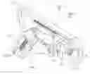
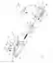
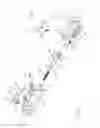
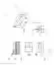
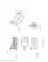
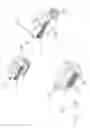
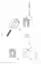
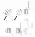
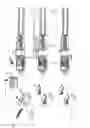
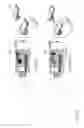
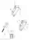
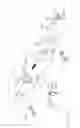
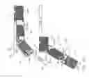
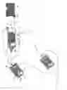
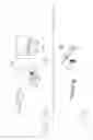
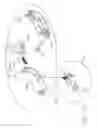
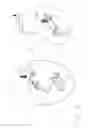
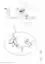
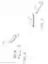


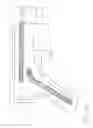
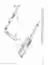
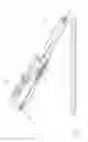
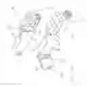
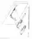
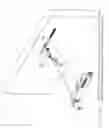
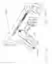
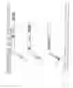
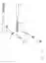
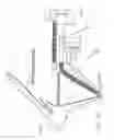
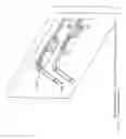
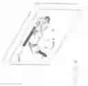
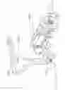
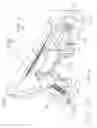

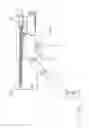


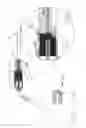
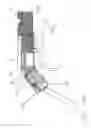
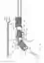
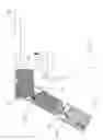
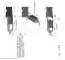
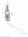
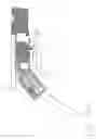
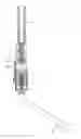
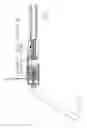
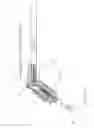
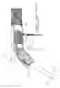

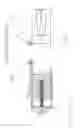
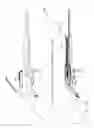

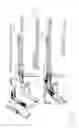
Sources:
- United States Patent and Trademark Office - verify current appl. status at the USPTO↗
Recent applications in this class:
- » 20180335265 2018-11-22
Reciprocating Action Universal Receiver Test System - » 20160341500 2016-11-24
Slide for a rifle - » 20160047610 2016-02-18
Shell loading system for firearm - » 20150330727 2015-11-19
Firearm with reciprocating bolt assembly - » 20150198393 2015-07-16
Ambidextrous rifle system - » 20150128468 2015-05-14
Bolt Spring Clip Assembly for a Firearm - » 20140338522 2014-11-20
Semi-automatic pistol - » 20140317981 2014-10-30
Unitary sear housing block - » 20140311004 2014-10-23
MANUALLY OPERATED FIREARM SYSTEM - » 20140260944 2014-09-18
Lock interface insert for machine gun bolt assembly