System level information for discontinuous reception, cell reselection and RACH
US20160192393A1
2016-06-30
14/918,960
2015-10-21
✅ Patent granted
US 9,532,377 B2
2016-12-27
-
-
Mohammad Adhami
Condo Roccia Koptiw, LLP
2035-10-21
Abstract:
A wireless transmit/receive unit is configured to receive system level information, including discontinuous reception (DRX) information, cell selection information, and RACH information. The system level information is received as defined parameters assigned to system information blocks or signaled through dedicated RRC signaling.
Inventors:
- Peter S. Wang 169 🇺🇸 E. Setauket, NY, United States
- Jin Wang 142 🇺🇸 Princeton, NJ, United States
- Shankar Somasundaram 67 🇺🇸 Sunnyvale, CA, United States
- Ulises Olvera-Hernandez 50 🇨🇦 Montreal, Canada
Assignee:
- INTERDIGITAL PATENT HOLDINGS, INC. 2,899 🇺🇸 Wilmington, DE, United States
Applicant:
Interested in similar patents?
Get notified when new applications in this technology area are published.
Classification:
H04W52/0216 » CPC further
Power management, e.g. TPC [Transmission Power Control], power saving or power classes; Power saving arrangements in terminal devices managed by the network, e.g. network or access point is master and terminal is slave using a pre-established activity schedule, e.g. traffic indication frame
H04W74/008 » CPC main
Wireless channel access, e.g. scheduled or random access; Transmission of channel access control information with additional processing of random access related information at receiving side
H04J11/0069 » CPC further
Orthogonal multiplex systems, e.g. using WALSH codes Cell search, i.e. determining cell identity [cell-ID]
H04W36/0005 » CPC further
Hand-off or reselection arrangements Control or signalling for completing the hand-off
H04W48/08 » CPC further
Access restriction ; Network selection; Access point selection Access restriction or access information delivery, e.g. discovery data delivery
H04W52/0225 » CPC further
Power management, e.g. TPC [Transmission Power Control], power saving or power classes; Power saving arrangements in terminal devices using monitoring of external events, e.g. the presence of a signal
H04W74/08 » CPC further
Wireless channel access, e.g. scheduled or random access Non-scheduled or contention based access, e.g. random access, ALOHA, CSMA [Carrier Sense Multiple Access]
H04J11/00 IPC
Orthogonal multiplex systems, e.g. using WALSH codes
H04W36/00 IPC
Hand-off or reselection arrangements
H04W52/02 IPC
Power management, e.g. TPC [Transmission Power Control], power saving or power classes Power saving arrangements
H04W48/16 » CPC further
Access restriction ; Network selection; Access point selection Discovering, processing access restriction or access information
H04W36/04 » CPC further
Hand-off or reselection arrangements Reselecting a cell layer in multi-layered cells
H04W74/00 IPC
Wireless channel access, e.g. scheduled or random access
Description
CROSS REFERENCE TO RELATED APPLICATIONS
This application is a continuation of U.S. patent application Ser. No. 12/185,546, filed Aug. 4, 2008, which claims the benefit of U.S. Provisional Application No. 60/953,816, filed Aug. 3, 2007, the entire contents of both of which being incorporated by reference as if fully set forth herein, for all purposes.
FIELD OF INVENTION
The present application is related to wireless communications.
BACKGROUND
The Third Generation Partnership Project (3GPP) has initiated the Long Term Evolution (LTE) program to bring new technology, new network architecture, new configurations and new applications and services to wireless cellular networks in order to provide improved spectral efficiency and faster user experiences.
In order for a wireless transmit receive unit (WTRU 101) to perform various procedures related to sleep, monitoring the paging cycles, cell reselection or using a random access channel (RACH), a network would typically signal a number of parameters to the WTRU in system information messages. Some of these parameters can also be used when the WTRU is in an active state, including, but not limited to, reduced neighbor cell lists, measurement reporting and handover parameters. There is a need to put all necessary parameters together and group them into system information messages for use by the WTRU in procedures and methods for sleep, reselection or RACH procedures.
Within a core network (CN) domain system information, information for a discontinuous reception (DRX) would typically be signaled to a WTRU 101 in idle mode in an information element (IE) (e.g., CN_DRX_cycle_length_coefficient). However, DRX exists in active mode as well as idle mode. Therefore, it would be beneficial to signal a DRX cycle length for the active mode.
When a WTRU 101 is camped on a cell, it regularly searches for a better cell according to a set of criteria. If a better cell is found, that cell is selected. In an LTE system with only two states LTE_Idle and LTE_active, the WTRU 101 can perform cell reselection only in the LTE_Idle state. The WTRU 101 uses parameters broadcasted from the system, including, but not limited to the following parameters that are transmitted in a system information block (SIB), such as SIB 3, SIB 4 and/or SIB 11:
-
- Qhyst1s: Used in ranking serving cell based on RSCP.
- Qhyst2s: Used in ranking serving cell based on Ec/Io.
- Qqualmin: Minimum required quality measure based on Ec/Io.
- Qrxlevmin: Minimum required quality measure based on a received signal power measurement (e.g., received signal code power (RSCP)).
- DeltaQrxlevmin: (conditional on value Delta) If present, the actual value of Qrxlevmin+DeltaQrxlevmin.
- UE_TXPWR_MAX_RACH: Maximum allowed uplink (UL) TX power
- Sintrasrch (optional): Measure intra-frequency neighbor cells when Squal≦Sintrasearch, where Squal is based on measured signal to interference ration of a corresponding cell measured by the WTRU 101 minus Qqualmin.
- Sintersrch (optional): Measure inter-frequency neighbor cells when Squal≦Sintersearch.
- SsearchHCS (optional): Measure inter-Hierarchal Cell Structure (HCS)/inter-frequency neighbor cells when Squal≦SsearchHCS.
- SHCS,RAT (optional): Measure inter-Hierarchal Cell Structure (HCS)/RAT neighbor cells when Squal≦SHCS,RAT.
- Slimit,SearchRAT (optional): This threshold is used in the measurement rules for cell re-selection when HCS is used. It specifies the RAT specific threshold (in dB) in the serving UTRA cell above which the UE may choose to not perform any inter-RAT measurements in RAT “m”.
SUMMARY
A wireless transmit/receive unit (WTRU 101) is configured to receive system level information, such as discontinuous reception (DRX) information, cell reselection information and random access channel (RACH) information, in the form of system information blocks (SIBs) or dedicated radio resource control (RRC) message signaling. The WTRU 101 autonomously processes the received parameters and alters its behavior with respect to sleep mode, cell reselection and using RACH signatures.
One or more techniques are contemplated for a wireless transmit/receive unit (WTRU), that may include receiving, via a receiver, information as a plurality of parameters defined as information elements (IEs) for a physical random access channel (PRACH) operation of the WTRU. Techniques may include processing, via a processor, the received parameters to perform PRACH operations by the WTRU. The IEs may include PRACH system information. The PRACH system information may include a random access channel (RACH) response window size. The RACH response window size may be provided as a number of subframes. Techniques may include receiving, via the receiver, one or more RACH responses sent to the WTRU over the RACH response window.
One or more techniques are contemplated for an evolved NodeB (eNB), where the eNB may include a processor. The processor may be configured to determine a plurality of parameters for physical random access channel (PRACH) operations. The plurality of parameters may include PRACH system information. The PRACH system information may include a random access channel (RACH) response window size. The RACH response window size may be provided as a number of subframes. The eNB may include a transmitter. The transmitter may be configured to transmit the plurality of parameters defined as information elements (IEs) for a PRACH operation of a wireless transmit/receive unit (WTRU). The transmitter may be configured to transmit one or more RACH responses to the WTRU over the RACH response window.
BRIEF DESCRIPTION OF THE DRAWING
A more detailed understanding may be had from the following description, given by way of example in conjunction with the accompanying drawings wherein:
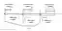
FIG. 1 shows a discontinuous reception (DRX) cycle; and
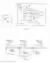
FIG. 2 shows a protocol layer stack configuration for a wireless transmit/receive unit receiving system level information from an evolved Node-B.
DETAILED DESCRIPTION
When referred to hereafter, the terminology “wireless transmit/receive unit (WTRU)” includes but is not limited to a user equipment (UE), a mobile station, a fixed or mobile subscriber unit, a pager, a cellular telephone, a personal digital assistant (PDA), a computer, or any other type of user device capable of operating in a wireless environment. When referred to hereafter, the terminology “base station” includes but is not limited to a Node-B, a site controller, an access point (AP), or any other type of interfacing device capable of operating in a wireless environment.
FIG. 1 shows a WTRU 101 comprising a protocol layer stack that includes the following layers: radio resource control RRC 102, radio link control (RLC) 103, medium access control (MAC) 104, packet data convergence protocol (PDCP) 105, and a physical (PHY) layer 106. These layer entities may be implemented as a single processor or separate processors. The WTRU 101 receives system level information from an evolved NodeB (eNB) 121 in a wireless downlink signal 111. The system level information may be defined in units of system information blocks (SIBs) and parameters within each of the SIBs may be used by the WTRU 101 for various processes which will be explained in further detail. The parameters may be defined into groups of information elements (IEs), which can be processed, for example, by the RRC 102 for controlling operation of the other layer entities. One example includes the RRC 102 receiving DRX parameters and then instructing the PHY 106 to sleep during the designated DRX cycle parameters.
In a first example of defining SIBs with system level information, a system information block 1 (SIB1) may be defined by information elements and related information as shown in Table 1. Each of the IEs shown in Table 1, as well as all tables shown herein, may be defined and provided to the WTRU 101 on a need basis that includes, but is not limited to, the following: mandatory, mandatory with a default value available, conditional on a value, or optional.
| TABLE 1 | |||
| Information | Type and | Semantics | |
| Group Name | Element | reference | description |
| CN information | CN common | NAS system | |
| elements | GSM-MAP | information | |
| NAS system | (GSM-MAP) | ||
| information | |||
| >Domain system | Domain system | ||
| information | information | ||
| (for PS domain) | |||
| WTRU 101 | WTRU Timers | WTRU Timers | The WTRU 101 |
| information | and constants | and constants | behaviour is |
| in idle mode | in idle mode | unspecified | |
| if this IE | |||
| is absent. | |||
| WTRU Timers | WTRU Timers | ||
| and constants | and constants | ||
| in active | in active | ||
| (connected) | (connected) | ||
| mode | mode | ||
As shown in Table 1, the core network (CN) IEs include common GSM-mobile application part (MAP) non-access stratum (NAS) system information and domain system information for the packet switched (PS) domain. These IEs inform the WTRU 101 about the serving CN and domain system. The LTE network operates only in a packet switched (PS) domain. Therefore, there is no need to maintain any other domain information. Only PS domain information is required to be signaled.
In the LTE specification, DRX operates in both explicit and implicit modes. DRX parameters may be signaled by two IEs that can carry specific DRX parameters for each mode of operation. The IE can carry both DRX explicit mode parameters and DRX implicit mode parameters. These IEs can be signaled with the domain system information or may be transmitted with another message, such as a RRC_Connection_Command message for example.
FIG. 2 shows a set of sequential DRX signal cycles, in which the WTRU 101 has an active period and a sleep period for the remainder of the DRX cycle, allowing the WTRU 101 to reduce battery consumption. The variable DRX parameters for defining the DRX cycle are the DRX cycle start time, the active period length and the DRX cycle length. For LTE idle mode, the WTRU 101 monitors system paging only during the active period. For LTE active mode, or RRC connected mode, the WTRU 101 only receives data during the active period. Adjustments to DRX parameters may become necessary, for example, to overcome poor channel conditions or to increase the amount of data reception upon the transition from LTE idle mode to LTE active mode. For DRX configuration, if the WTRU 101 is in LTE active mode, the network can signal the same or different parameters as for the WTRU 101 in LTE idle mode. Also, the network may group the parameters and identify the group with a DRX profile identifier (ID). This may enable the network to signal the WTRU 101 to use a particular profile. The signaling received by the WTRU 101 may be through RRC or MAC signaling and may provide the DRX cycle start time, as shown in FIG. 2.
Table 2 shows an example of LTE idle mode and LTE active mode DRX configuration IEs and associated parameters for this embodiment, for which the WTRU 101 is configured to receive and process. An IE for CN DRX cycle period length in LTE idle mode indicates the length of the entire DRX cycle for the WTRU 101 to use while receiving paging in idle mode. An IE for LTE active mode parameters indicates to the WTRU 101 whether LTE active mode parameters are to be the same as the idle mode parameters, or different than the idle mode parameters. If different, the network may then specify a different set of active mode parameters. In order to allow the WTRU 101 to synchronize to the DRX cycle, an IE for DRX cycle start time is defined. In this example, the cell system frame number (SFN) is used as a reference for the DRX cycle start time. A choice IE, Choice Signaling Method, is defined by the network and received by the WTRU 101 to indicate the type of DRX signaling method being employed, which is either explicit type or implicit type, explained later in further detail with respect to Tables 3 and 4.
| TABLE 2 |
| LTE Active mode and LTE Idle mode |
| Information Element/ | Type and | Semantics |
| Group name | reference | description |
| CN DRX cycle period | Integer | Refers to the length of the |
| length In LTE Idle | (1 . . . x) | entire DRX cycle in WTRU |
| Mode | Idle mode for paging. | |
| LTE_Active Mode DRX | Enumerated | Network specifies whether |
| parameters | (same as Idle, | the Active mode DRX |
| different) | parameters are the same as | |
| or different than the Idle | ||
| mode parameters. | ||
| If specified that the | ||
| Active mode DRX parameters | ||
| are different, network may | ||
| specify a different set of | ||
| values for the Active mode | ||
| parameters. | ||
| >DRX Cycle Start | Integer | Configured DRX Cycle in |
| Time | (0 . . . 4093) | LTE_Active starts on an |
| SFN | ||
| >CHOICE Signaling | ||
| method | ||
| >> Explicit | ||
| >>> Explicit DRX | Explicit DRX | |
| Configuration | Configuration | |
| Info (Table 3) | ||
| >> Implicit | ||
| >>> Implicit DRX | Implicit DRX | |
| Configuration | Configuration | |
| Info (Table 4) | ||
Table 3 shows a summary of an exemplary configuration for information elements used in explicit DRX signaling. As a choice IE, the DRX configuration mode may indicate either a Full Configuration or a Predefined Configuration mode. For the Full Configuration mode, the network provides all of the DRX parameters to the WTRU 101. In the Predefined Configuration mode, the WTRU 101 uses default DRX parameters that are predefined by the network. The DRX profile ID information element can be used for defining different DRX profiles which can be used for changing the DRX lengths and other parameters during various procedures, including 3GPP to non-3GPP handovers.
| TABLE 3 |
| Explicit DRX |
| Information Element/ | Type and | Semantics |
| Group Name | reference | description |
| Choice DRX | ||
| Configuration Mode | ||
| > Full Configuration | ||
| >>DRX Cycle length | Integer | DRX Cycle Length in unit |
| in LTE Active mode | (1 . . . X) | of the number of system |
| frames | ||
| >>Active period | Integer | Active duty cycle length |
| length in LTE | (1 . . . 10) | in unit of sub-frames |
| Active mode | ||
| >>Active period | Enumerated | Indicating the active |
| position | (first, last) | duty period is in the |
| beginning or the end of | ||
| the cycle | ||
| >> Active period | Integer | The sub-frame number at |
| start sub-frame | (1, . . . , 9) | which the active period |
| starts in its first | ||
| frame, if it is not on | ||
| frame boundary | ||
| > Predefined | ||
| Configuration | ||
| >> DRX profile ID | Integer | Network signals a profile |
| (1 . . . X) | ID with the set of | |
| already defined | ||
| parameters when it wants | ||
| the WTRU 101 to use a | ||
| predefined configuration | ||
Table 4 shows a summary of an exemplary configuration for information elements used in implicit DRX signaling. As shown, the IE for Implicit DRX State and Transition List may have multiple instances in the signaling to the WTRU 101, one per maximum number of DRX states. Similar to the Explicit DRX explained above, there is a choice IE for DRX configuration mode, for either a Predefined configuration or a Full Configuration. Under a Full configuration mode, trigger mechanism IEs Trigger-UP-1, Trigger-Down-1 and Trigger-Down-2 are defined. The Trigger-UP-1 IE indicates the WTRU 101 is to move to the next upper level DRX state (i.e., a longer DRX cycle). The Trigger-Down-1 IE is a trigger mechanism for the WTRU 101 to move the next lower level DRX state (i.e., a shorter DRX cycle). For the Trigger-Down-2 IE, the WTRU 101 receives a trigger mechanism to move to the shortest DRX cycle, Level-1. For each of these trigger IEs, a choice IE for Triggering Mechanism includes either a timer or a measurement event, as summarized in Table 5. If a timer trigger mechanism is applied, a timer value IE, Implicit-DRX-triggering-timer, may be included. For a measurement event trigger, an Implicit DRX triggering event IE may be included, based on traffic volume and/or inter-frequency, intra-frequency, inter-RAT, intra-RAT measurement events, and an IE for threshold value to be used for the measurement event may also be included.
| TABLE 4 |
| Implicit DRX |
| Information Element/ | Type and | Semantics | |
| Group name | Multiple | reference | description |
| Initial DRX state | |||
| Implicit DRX | Time in seconds | ||
| Transition | |||
| configured life span | |||
| Implicit DRX State | <1, . . . , | ||
| and Transition List | maxDRX | ||
| states> | |||
| CHOICE DRX- | |||
| Config-Mode | |||
| > Predefined | |||
| Configuration | |||
| CN DRX profile ID | Integer | Network could signal a | |
| (1 . . . X) | profile ID with each of the | ||
| parameters and so the | |||
| network could signal the | |||
| WTRU 101 to use a | |||
| particular DRX profile ID | |||
| when it wants the WTRU | |||
| 101 to use a predefined | |||
| configuration | |||
| > Full | |||
| Configuration | |||
| >>DRX Cycle | Integer | ||
| Length | |||
| >>Trigger-UP-1 | Trigger Mechanism (Table 5) | To next upper level DRX | |
| State | |||
| >>Trigger-Down-1 | Trigger Mechanism (Table 5) | To next lower level DRX | |
| state | |||
| >>Trigger-Down-2 | Trigger Mechanism (Table 5) | To Level-1 (shortest DRX | |
| cycle) trigger | |||
| >>>DRX Cycle | Integer | DRX Cycle Length in unit | |
| length in LTE | (1 . . . X) | of the number of system | |
| Active mode | frames | ||
| >>>Active period | Integer | Active duty cycle length in | |
| length in LTE | (1 . . . 10) | unit of sub-frames | |
| Active mode | |||
| >>>Active period | Enumerated | Indicating the active duty | |
| position | (first, last) | period is in the beginning | |
| or the end of the cycle [this | |||
| may not be needed if we | |||
| have the system define | |||
| that the active period | |||
| always starts in the first | |||
| frame of the DRX cycle] | |||
| >>> Active period | Integer | The sub-frame number at | |
| start sub-frame | (1, . . . , 9) | which the active period | |
| starts in its first frame, if | |||
| it is not on the frame | |||
| boundary | |||
| TABLE 5 |
| Triggering mechanisms |
| Information Element/ | Type and | Semantics | |
| Group name | reference | description | |
| CHOICE triggering- | |||
| mechanism | |||
| > Timer | |||
| >>Implicit-DRX- | Integer (10, 20, | Timer value in | |
| triggering-timer | 50, 100, 200, 500, | unit of | |
| 1000, . . . X) | milli-seconds | ||
| > Measurement-event | Integer | ||
| (1 . . . 10) | |||
| >>Implicit-DRX- | Measurement | Traffic volume | |
| triggering-event | Event ID | measurement | |
| events & | |||
| inter/intra F/R | |||
| measurement | |||
| events | |||
| >> Event-associated | |||
| threshold value | |||
Additional IEs provided to the WTRU 101 for defining the DRX cycle may include DRX Cycle length, the active period length, the active period position and the active period start subframe. For the DRX cycle length IE, the parameter indicates the DRX cycle length for LTE active mode in units of system frames and indicating if this DRX parameter is different than the LTE idle mode parameter. The active period length IE indicates the active duty cycle length in sub-frames for LTE active mode, and whether the parameter is different than the LTE idle mode parameter. The active period position IE indicates whether the active duty period is at the beginning or at the end of the DRX cycle whether the parameter is different than the LTE idle mode parameter. If the active period does not start at a frame boundary, then the active period start sub-frame IE provides the sub-frame number at which the active period starts.
In another embodiment, parameters for cell selection and reselection are defined and transmitted in a SIB 3, for example, or one of the other SIBs defined in the 3GPP specifications. Tables 6 and 7 show a summary of an example configuration of IEs containing cell selection and reselection parameters.
| TABLE 6 |
| Cell Selection and Reselection |
| Information Element/ | Type and | Semantics |
| Group name | reference | description |
| SIB4 Indicator | Boolean | TRUE indicates that SIB4 is broadcast in |
| the cell. | ||
| UTRAN mobility | ||
| information elements | ||
| Cell identity | Cell identity | |
| Cell selection and | Cell selection | |
| re-selection info | and re-selection | |
| info for SIB3/4 | ||
| Cell Access | Cell Access | |
| Restriction | Restriction | |
| Access Restriction | Access | This IE specifies the Access Restriction |
| Parameters For | Restriction | Parameters for WTRUs which have chosen |
| PLMN Of MIB | Parameters | the PLMN in the IE “PLMN identity” of the |
| Master Information Block. | ||
| Domain Specific | ||
| Access Restriction | ||
| For Shared Network | ||
| >CHOICE barring | ||
| representation | ||
| >> Access | ||
| Restriction | ||
| Parameter List | ||
| >>> Access | PS Domain | This IE specifies the Access Restriction |
| Restriction | Specific | Parameters for WTRUs which have chosen |
| Parameters For | Access | the first PLMN in the IE “multiplePLMNs” |
| Operator1 | Restriction | in the IE “Multiple PLMN List” of the |
| Parameters | Master Information Block. | |
| >>> Access | PS Domain | This IE specifies the Access Restriction |
| Restriction | Specific | Parameters for WTRUs which have chosen |
| Parameters For | Access | the second PLMN in the IE |
| Operator2 | Restriction | “multiplePLMNs” in the IE “Multiple |
| Parameters | PLMN List” of the Master Information | |
| Block. | ||
| >>> Access | PS Domain | This IE specifies the Access Restriction |
| Restriction | Specific | Parameters for WTRUs which have chosen |
| Parameters For | Access | the third PLMN in the IE |
| Operator3 | Restriction | “multiplePLMNs” in the IE “Multiple |
| Parameters | PLMN List” of the Master Information | |
| Block. | ||
| >>> Access | PS Domain | This IE specifies Access Restriction |
| Restriction | Specific | Parameters for WTRUs which have chosen |
| Parameters For | Access | the fourth PLMN in the IE |
| Operator4 | Restriction | “multiplePLMNs” in the IE “Multiple |
| Parameters | PLMN List” of the Master Information | |
| Block. | ||
| >>> Access | PS Domain | This IE specifies the Access Restriction |
| Restriction | Specific | Parameters for WTRUs which have chosen |
| Parameters For | Access | the fifth PLMN in the IE “multiplePLMNs” |
| Operator5 | Restriction | in the IE “Multiple PLMN List” of the |
| Parameters | Master Information Block. | |
| >> Access | ||
| Restriction | ||
| Parameters For | ||
| All | ||
| >>> Access | PS Domain | This IE specifies the common Access |
| Restriction | Specific | Restriction Parameters applied to all |
| Parameters | Access | PLMNs in the IE “multiplePLMNs” in the |
| Restriction | IE “Multiple PLMN List” of the Master | |
| Parameters | Information Block. | |
As seen in Table 6, for a choice IE for barring representation, either an IE “Access restriction parameter list” IE or an “Access restriction parameter for all” IE is selected. If the “Access restriction parameter list” IE is applied, then multiple IEs are available for specifying access restriction parameters for WTRUs assigned to a respective public land mobile network (PLMN), which is identified in an IE “multiplePLMNs” in the IE “Multiple PLMN List” in the master information block (MIB). When the “Alternative access restriction parameters for all” IE is chosen, then a set of common access restriction parameters is indicated to the WTRU 101, which is applied to all PLMNs in the IE “multiple PLMNs”. As there is one PS domain, the parameters for the CS domain are not specified.
As shown in Table 7, the WTRU 101 may receive an IE for Cell selection and reselection quality measure based on RSRP and/or RSRQ, an IE for radio access technology (RAT) of the candidate cell for selection, and a Treslection IE that indicates the reselection time parameter. With respect to the Qhyst IE, the WTRU 101 may receive the following scaling factors: an IE that indicates a Speed dependent scaling factor, an Inter-frequency Speed dependent scaling factor, and an Inter RAT Speed dependent scaling factor. A Neighbor cell blacklist IE may be received by the WTRU 101 to indicate a list of neighbor cells forbidden by the network for reselection.
Before the WTRU 101 makes received signal measurements for cell selection/reselection, the WTRU 101 may receive and process an UTRAN_min IE or GERAN_Min which indicate the minimum signal power for a UTRAN or GERAN cell, respectively. The IEs Qoffset1 and Qoffset2 may be received by the WTRU 101 to indicate biasing cell measurements
| TABLE 7 |
| Cell selection and reselection |
| Information Element/ | Type and | Semantics | |
| Group name | Multiple | reference | description |
| Cell selection and | Enumerated | Choice of measurement (RSRP or | |
| reselection quality | (RSRP, RSRQ) | RSRQ) to use as quality measure Q | |
| measure | for FDD cells. | ||
| This IE is also sent to the WTRU | |||
| in SIB11/12. Both occurrences of | |||
| the IE should be set to the same | |||
| value. | |||
| CHOICE mode | |||
| >FDD | |||
| >>Sintrasearch | Integer | If a negative value is received the | |
| (−32 . . . 20 | WTRU considers the value to be 0. | ||
| by step of 2) | [dB] | ||
| >>Sintersearch | Integer | If a negative value is received the | |
| (−32 . . . 20 | WTRU considers the value to be 0. | ||
| by step of 2) | [dB] | ||
| >>SsearchHCS | Integer | If a negative value is received the | |
| (−105 . . . 91 | WTRU considers the value to be 0. | ||
| by step of 2) | [dB] | ||
| >>RAT List | 1 to | ||
| <maxOther | |||
| RAT> | |||
| >>>RAT identifier | Enumerated (GSM, | ||
| CDMA2000, | |||
| UTRAN, any other | |||
| non 3GPP RAT like | |||
| WiFi, WiMAx, | |||
| UMA etc) | |||
| >>QSearch_TH | Integer | In case the value 20 is received the | |
| (−32 . . . 20 | WTRU considers this IE as if it | ||
| by step of 2) | was absent. | ||
| If a negative value is received the | |||
| WTRU considers the value to be 0. | |||
| [dB] | |||
| >>>SHCS, RAT | Integer | If a negative value is received the | |
| (−105 . . . 91 | WTRU considers the value to be 0. | ||
| by step of 2) | [dB] | ||
| >>>Slimit, SearchRAT | Integer | If a negative value is received the | |
| (−32 . . . 20 | WTRU considers the value to be 0. | ||
| by step of 2) | [dB] | ||
| >>Qqualmin | Integer | RSRP, [dB] | |
| (−24 . . . 0) | |||
| >>Qrxlevmin | Integer | RSRQ, [dBm] | |
| (−115 . . . −25 | |||
| by step of 2) | |||
| >> DeltaQrxlevmin | Integer | If present, the actual value of | |
| (−4 . . . −2 | Qrxlevmin = Qrxlevmin + | ||
| by step of 2) | DeltaQrxlevmin | ||
| >TDD | |||
| >>Sintrasearch | Integer | If a negative value is received the | |
| (−105 . . . 91 | WTRU considers the value to be 0. | ||
| by step of 2) | [dB] | ||
| >>Sintersearch | Integer | If a negative value is received the | |
| (−105 . . . 91 | WTRU considers the value to be 0. | ||
| by step of 2) | [dB] | ||
| >>SsearchHCS | Integer | If a negative value is received the | |
| (−105 . . . 91 | WTRU considers the value to be 0. | ||
| by step of 2) | [dB] | ||
| >>RAT List | 1 to | ||
| <maxOther- | |||
| RAT> | |||
| >>>Ssearch, RAT | Integer | In case the value 91 is received the | |
| (−105 . . . 91 | WTRU considers this IE as if it | ||
| by step of 2) | was absent. | ||
| If a negative value is received the | |||
| WTRU considers the value to be 0. | |||
| [dB] | |||
| >>>SHCS, RAT | Integer | If a negative value is received the | |
| (−105 . . . 91 | WTRU considers the value to be 0. | ||
| by step of 2) | [dB] | ||
| >>>Slimit, SearchRAT | Integer | If a negative value is received the | |
| (−105 . . . 91 | WTRU considers the value to be 0. | ||
| by step of 2) | [dB] | ||
| >>Qrxlevmin | Integer | RSCP, [dBm] | |
| (−115 . . . −25 | |||
| by step of 2) | |||
| >>DeltaQrxlevmin | Integer | If present, the actual value of | |
| (−4 . . . −2 | Qrxlevmin = Qrxlevmin + | ||
| by step of 2) | DeltaQrxlevmin | ||
| Qhyst1s | Integer | [dB] | |
| (0 . . . 40 | |||
| by step of 2) | |||
| Qhyst2s | Integer | Default value is Qhyst1s | |
| (0 . . . 40 | [dB] | ||
| by step of 2) | |||
| Treselections | Integer | [s] | |
| (0 . . . 31) | |||
| Speed dependent | Real | This IE is used by the WTRU in | |
| ScalingFactor for | (0 . . . 1 | high mobility state as scaling | |
| Treselection | by step of 0.1) | factor for Treselections | |
| Inter-frequency | Real | If present, it is used by the WTRU | |
| ScalingFactor for | (1 . . . 4.75 | as scaling factor for Treselections | |
| Treselection | by step of 0.25) | for inter-frequency cell reselection | |
| evaluation | |||
| Inter-RAT | Real | If present, it is used by the WTRU | |
| ScalingFactor for | (1 . . . 4.75 | as scaling factor for Treselections | |
| Treselection | by step of 0.25) | for inter-RAT cell reselection | |
| evaluation | |||
| Speed dependent | Real | If present, it is used by the WTRU | |
| Scaling factor for | (0 . . . 1 | as scaling factor for Qhyst for | |
| Qhyst | by step of 0.1) | inter-RAT cell reselection | |
| evaluation | |||
| Inter-frequency | Real | If present, it is used by the WTRU | |
| Speed dependent | (1 . . . 4.75 | as scaling factor for Qhysts for | |
| Scaling factor for | by step of 0.25) | inter-RAT cell reselection | |
| Qhyst | evaluation | ||
| Inter-RAT Speed | Real | If present, it is used by the WTRU | |
| dependent Scaling | (1 . . . 4.75 | as scaling factor for Qhyst for | |
| factor for Qhyst | by step of 0.25) | inter-RAT cell reselection | |
| evaluation | |||
| Neighbour cell | Integer(neighbour | Network can specify the list of cells | |
| blacklist | cell IDs) | it does not want the WTRU to | |
| reselect to if it so desires | |||
| Non-HCS_TCRmax | Enumerated (not | [s] | |
| used, 30, 60, | Default value is ‘not used’. | ||
| 120, 180, 240) | |||
| Non-HCS_NCR | Integer | Default value = 8 | |
| (1 . . . 16) | |||
| Non-HCS_TCRmaxHyst | Enumerated (not | [s] | |
| used, 10, 20, 30, | |||
| 40, 50, 60, 70) | |||
| HCS Serving cell | HCS Serving cell | ||
| Information | information | ||
| Maximum allowed | Maximum allowed | [dBm] UE_TXPWE_MAX_EACH | |
| UL TX power | UL TX power | ||
| UTRAN_Min/ | Minimum value | [dBm] | |
| above which the | |||
| UTRAN cell should | |||
| be to start | |||
| measurements. | |||
| GERAN_Min | Minimum value | [dBm] | |
| above which the | |||
| GERAN cell should | |||
| be to start | |||
| measurements. | |||
| Qoffset1 | Value used for | [dBm] | |
| biasing the cells | |||
| for measurement | |||
| Qoffset2 | Another offset | [dBm] | |
| value used based | |||
| on cell loading | |||
| or any other | |||
| parameter | |||
| Tmeas | Number of seconds | [s] | |
| between two | |||
| consecutive | |||
| measurements in | |||
| Idle for Inter-RAT | |||
| Priority of | Priority of RAT | Enumerated (GSM, cdma2000, | |
| Inter-RAT | selection during the | UTRAN, any other non 3GPP RAT | |
| reselection | Inter-RAT | like WiFi, WiMAx, etc) | |
| reselection process. | |||
| WTRU would follow | |||
| this list in order. | |||
In another embodiment, system level information for a PHY random access channel (PRACH) is defined by parameters in IEs and included into an SIB 5, or another 3GPP specified SIB, to be received and processed by the WTRU 101. Tables 8-10 show a summary of example configurations of such IEs and related information.
As shown in Table 8, a PRACH system information IE may be included with multiple instances from 1 to maxPRACH. A PRACH-info IE for RACH comprises several IEs that are summarized in Table 9. A RACH non-dedicated signature IE indicates dedicated and non-dedicated signatures allocated to the WTRU 101, and comprises several IEs that are summarized in Table 10. A RACH Response Window IE informs the WTRU 101 as to a number of sub-frames over which multiple RACH responses sent to the WTRU 101 are to be received. A PHY downlink control channel (PDCCH) information IE, “PDCCH-Info”, provides PDCCH parameters for the PRCAH to the WTRU 101, comprising IEs summarized in Table 12. A routing area-radio network temporary identification (RA-RNTI) List IE, comprising IEs summarized in Table 11, provides RNTI information to the WTRU 101 for the routing area.
| TABLE 8 |
| PRACH system information |
| Type and | Semantics | ||
| Information element | Multiple | reference | description |
| PRACH system | 1 . . . | ||
| information | <maxPRACH> | ||
| >PRACH info | PRACH | ||
| info (for | |||
| RACH), see | |||
| Table 9 | |||
| >CHOICE mode | |||
| >>FDD | |||
| >>>Primary CPICH | Primary TX | Default value is the value of “Primary | |
| TX power | power | Reference Symbol TX power” for the | |
| previous PRACH in the list. | |||
| (The first occurrence is then | |||
| mandatory) | |||
| >>>Constant value | Constant | Default value is the value of “Constant | |
| value | value” for the previous PRACH in the | ||
| list. | |||
| (The first occurrence is then | |||
| mandatory) | |||
| >>>PRACH power | PRACH | Default value is the value of “PRACH | |
| offset | power offset | power offset” for the previous PRACH | |
| in the list. | |||
| (The first occurrence is then | |||
| mandatory) | |||
| >>>RACH | RACH | Default value is the value of “RACH | |
| transmission | transmission | transmission parameters” for the | |
| parameters | parameters | previous PRACH in the list. | |
| (The first occurrence is then | |||
| mandatory) | |||
| >>>RACH non- | RACH non- | Dedicated and Non dedicated | |
| dedicated-signature | dedicated- | signatures allocated to the WTRU | |
| signature | |||
| parameters | |||
| See Table 10 | |||
| >>> RACH Response | Integer | RACH window (in number of sub- | |
| Window | (1, . . . , 10) | frames) over which multiple responses | |
| sent to the WTRU are received. | |||
| >>>PDCCH Info | PDCCH | Default value is the value of “PDCCH | |
| info See | info” for the previous PRACH in the | ||
| Table 12 | list. | ||
| (The first occurrence is then | |||
| mandatory) | |||
| >>> RA-RNTI List | RA-RNTI | Default value is the value of “RA-RNTI | |
| Info | List” for the previous PRACH in the | ||
| See Table 11 | list. | ||
| (The first occurrence is then | |||
| mandatory) | |||
As shown in Table 9, WTRU 101 receives PRACH information parameters for frequency division duplex (FDD) and time division duplex (TDD) operation. For FDD, the WTRU 101 may receive a PRACH frequency position IE indicating an integer value within a range starting from the lowest frequency edge of the carrier bandwidth. Alternatively, the integer value may range between negative and positive values centered in the middle of the carrier frequency. Additional parameters received by the WTRU 101 include a PRACH burst type IE (e.g., normal, extended or repeated burst type) and a Channel Coding parameter IE for identifying the turbo code in use. For TDD, the WTRU 101 may receive a PRACH Frame structure type IE and a PRACH Burst Type IE to indicate, for example, a normal or extended burst type.
| TABLE 9 |
| PRACH information |
| Information Element/ | Type and | Semantics |
| Group name | reference | description |
| CHOICE mode | ||
| >FDD | ||
| >>PRACH Frequency | Integer | Resource Block number |
| Position (on | (0, . . . , 105) | scale starts from the |
| beginning RB | lowest frequency edge | |
| number of the PRACH) | of the carrier | |
| bandwidth | ||
| OR | ||
| >>PRACH Frequency | Integer | RB number scale for |
| Position (on | (−52, . . . , | 105 RBs with center |
| beginning RB | 0, . . . +52) | in the middle of the |
| number of the PRACH) | carrier frequency | |
| >>PRACH Burst Type | Enumerated | |
| (Normal, | ||
| Extended, | ||
| Repeated) | ||
| >> Channel Coding | Integer | Identification of the |
| Parameter | (0, . . . xx) | turbo code |
| >>Preamble | Integer | Identification of |
| scrambling code | (0 . . . 15) | scrambling code |
| number | see [28] | |
| >>Puncturing Limit | Real | |
| (0.40 . . . 1.00 | ||
| by step of 0.04) | ||
| >TDD | ||
| >>PRACH Frame | Enumerated | |
| Structure | (Type-1, Type-2) | |
| >>PRACH Burst Type | Enumerated | |
| (Normal, | ||
| Extended) | ||
| >> TBD | ||
As shown in Table 10, the WTRU 101 may receive a set of RACH parameters defined according to a group G1 for dedicated RACH signatures, a group G2 for consecutive or bit-mapped non-dedicated RACH signatures, or a group G3 for small message consecutive or bit-mapped non-dedicated RACH signatures. Each RACH channel typically has 64 random access signatures of cyclical Z-C codes whose generation/derivation is specified in 3GPP Standards. For system information, the signatures can be identified by their indexes (0, . . . , 63).
When a random access signature group whose signatures are all consecutive in terms of the signature index, it can be defined by [start-index-a, range]. The WTRU 101 then knows and selects the signatures within the defined group since they are consecutive. For example, WTRU 101 receives the Available Dedicated Signatures G1 IE, the Number of Signatures IE with a value 8, and a Begin Signature Index IE with value 8, then WTRU 101 can derive that its RACH signature group is [8-15].
But if the random access signatures in a group is not consecutive, then the above described signature index mapping IE is replaced by the alternative bit-mapped signature index, shown in Table 10 as the Signature Map IE. For the bit-mapped signature mapping, the WTRU 101 receives a bit string which indicates a set of available signatures in the random access signature group according to a predefined signature map. The Signature map IE use a bitmap with 64 bits, or with a first start-index-a, and a subsequent bitmap in a range.
| TABLE 10 |
| RACH Non-dedicated Preamble/signatures |
| Information Element/ | Type and | Semantics |
| Group name | reference | description |
| CHOICE mode | ||
| >FDD | ||
| Available Dedicated | ||
| Signatures G1 | ||
| >>> Number of | Integer (0, | consecutive signatures in |
| signatures | 4, 8, 16, 24) | the group |
| >>> Begin Signature | Integer | Index number of the first |
| Index | (0, . . . , 63) | signature, present only |
| if the number of | ||
| signatures of the group | ||
| is not zero | ||
| >>Available | ||
| Non-dedicated | ||
| Signatures G2 | ||
| >>> Number of | Integer (0, | Number of consecutive |
| signatures | 4, 8, 16, 24, | signatures in the group |
| 32, 48, 64) | ||
| >>> Begin Signature | Integer | Index number of the first |
| Index | (0, . . . , 63) | signature, present only |
| if the number of | ||
| signatures of the group | ||
| is not zero | ||
| OR If signatures | ||
| not consecutive | ||
| >>> Signature map | Bit string | Set bit positions in the |
| (64) | map indicate the indexes | |
| of available signatures | ||
| in the group | ||
| >>Available | ||
| Non-dedicated | ||
| Signatures G3 | ||
| >>> Number of | Integer (0, | Number of consecutive |
| signatures | 4, 8, 16, 24, | signatures in the group |
| 32, 48, 64) | ||
| >>> Begin | Integer | Index number of the first |
| Signature Index | (0, . . . , 63) | signature, present only |
| if the number of | ||
| signatures of the group | ||
| is not zero | ||
| OR If signatures | ||
| not consecutive [ | ||
| >>> Signature map | Bit string | Set bit positions in the |
| (64) | map indicating the | |
| indexes of available | ||
| signatures in the group | ||
| TABLE 11 |
| RACH RA-RNTI Information |
| Information Element/ | Type and | Semantics | |
| Group name | Multi | reference | description |
| RACH RA-RNTI Info | <1, . . . , | At least 2 for | |
| maxRA- | a RACH, 3 or | ||
| RNTI | more for | ||
| better | |||
| decoding | |||
| >RA-RNTI Code | Bit String | ||
| (12 or 16 | |||
| or ?) | |||
| >Burst Start | Integer | A burst is a | |
| subframe number | (0, . . . , 9) | sub-frame | |
| >Next Burst | Integer | N sub-frames, | |
| Distance | (4, . . . , 20) | equivalent to | |
| the RACH | |||
| response | |||
| window size | |||
| TABLE 12 |
| PDCCH Information |
| Information Element/ | Type and | Semantics | |
| Group name | Need | reference | description |
| PDCCH Info | MP | ||
| >PDCCH Format | MP | Enumerated | |
| (0, 1, 2, 3) | |||
| >PDCCH Scrambling | OP | Integer | Index to the |
| (0, . . . , x) | scrambling code | ||
| tree | |||
Other than the SIBs mentioned above, the LTE network could also transmit a SIB 16 message which could carry some configuration parameters that the WTRU 101 could read and use when entering the LTE system during a handover from another RAT (3GPP or non-3GPP) to LTE. Alternatively, the LTE system could transmit a SIB 16 message or some other analogous dedicated RRC message which would carry parameters applicable for the non 3GPP RAT during a handover from LTE to other RAT (3GPP or non-3GPP). Such a message could have been possibly conveyed to the LTE system just before the handover procedure. This SIB 16 could contain a combination of parameters like some of the DRX parameters mentioned, some RACH and reselection parameters and any other physical layer parameters which might give the WTRU 101 some knowledge of the system.
Although features and elements are described above in particular combinations, each feature or element can be used alone without the other features and elements or in various combinations with or without other features and elements. The methods or flow charts provided herein may be implemented in a computer program, software, or firmware incorporated in a computer-readable storage medium for execution by a general purpose computer or a processor. Examples of computer-readable storage mediums include a read only memory (ROM), a random access memory (RAM), a register, cache memory, semiconductor memory devices, magnetic media such as internal hard disks and removable disks, magneto-optical media, and optical media such as CD-ROM disks, and digital versatile disks (DVDs).
Suitable processors include, by way of example, a general purpose processor, a special purpose processor, a conventional processor, a digital signal processor (DSP), a plurality of microprocessors, one or more microprocessors in association with a DSP core, a controller, a microcontroller, Application Specific Integrated Circuits (ASICs), Field Programmable Gate Arrays (FPGAs) circuits, any other type of integrated circuit (IC), and/or a state machine.
A processor in association with software may be used to implement a radio frequency transceiver for use in a wireless transmit receive unit (WTRU), user equipment (UE), terminal, base station, radio network controller (RNC), or any host computer. The WTRU may be used in conjunction with modules, implemented in hardware and/or software, such as a camera, a video camera module, a videophone, a speakerphone, a vibration device, a speaker, a microphone, a television transceiver, a hands free headset, a keyboard, a Bluetooth® module, a frequency modulated (FM) radio unit, a liquid crystal display (LCD) display unit, an organic light-emitting diode (OLED) display unit, a digital music player, a media player, a video game player module, an Internet browser, and/or any wireless local area network (WLAN) or Ultra Wide Band (UWB) module.
Claims
What is claimed is:1. A method performed by a wireless transmit/receive unit (WTRU), the method comprising:
receiving, via a receiver, information as a plurality of parameters defined as information elements (IEs) for a physical random access channel (PRACH) operation of the WTRU;
processing, via a processor, the received parameters to perform PRACH operations by the WTRU, the IEs including PRACH system information, the PRACH system information including a random access channel (RACH) response window size, the RACH response window size provided as a number of subframes; and
receiving, via the receiver, one or more RACH responses sent to the WTRU over the RACH response window.
2. The method of claim 1, wherein the PRACH system information further comprises PDCCH information and RA-RNTI information.
3. The method of claim 1, wherein the PRACH system information further comprises at least one of: PRACH burst type information, PRACH frequency position information, or a channel coding parameter.
4. The method of claim 1, wherein the PRACH system information further comprises at least one of: a PRACH burst type parameter, or a PRACH frame structure parameter.
5. The method of claim 1, wherein the IEs include RACH non-dedicated preamble and signature information.
6. The method of claim 5, wherein the RACH non-dedicated preamble and signature information includes at least one of the following parameters: a number of signatures, a begin signature index, or a signature map.
7. The method of claim 1, wherein the IEs include RACH dedicated preamble and signature information.
8. The method of claim 7, wherein the RACH dedicated preamble and signature information includes at least one of the following parameters: a number of signatures, or a begin signature index.
9. The method of claim 2, wherein the RA-RNTI information includes at least one of the following parameters: a RA-RNTI code, a burst start sub-frame number or a next burst distance.
10. The method of claim 2, wherein the PDCCH information includes at least one of the following parameters: a PDCCH format, or a PDCCH scrambling code.
11. A wireless transmit/receive unit (WTRU) comprising:
a receiver, the receiver configured to receive information as a plurality of parameters defined as information elements (IEs) for a physical random access channel (PRACH) operation of the WTRU; and
a processor, the processor configured to process the received parameters to perform PRACH operations, the IEs including PRACH system information, the PRACH system information including a random access channel (RACH) response window size, the RACH response window size provided as a number of subframes, the receiver being further configured to:
receive one or more RACH responses sent to the WTRU over the RACH response window.
12. The WTRU of claim 11, wherein the PRACH system information further includes PDCCH information and RA-RNTI information, the RA-RNTI information including at least one of the following parameters: a RA-RNTI code, a burst start sub-frame number or a next burst distance, and the PDCCH information including at least one of the following parameters: a PDCCH format or a PDCCH scrambling code.
13. The WTRU of claim 11, wherein the PRACH system information further includes at least one of: PRACH burst type information, PRACH frequency position information, a channel coding parameter, or a PRACH frame structure parameter.
14. The WTRU of claim 11, wherein the IEs include RACH non-dedicated preamble and signature information, the RACH non-dedicated preamble and signature information including at least one of the following parameters: a number of signatures, a begin signature index, or a signature map.
15. The WTRU of claim 11, wherein the IEs include RACH dedicated preamble and signature information, the RACH dedicated preamble and signature information including at least one of the following parameters: a number of signatures or a begin signature index.
16. An evolved NodeB (eNB), the eNB comprising:
a processor, the processor configured to determine a plurality of parameters for physical random access channel (PRACH) operations, the plurality of parameters including PRACH system information, the PRACH system information including a random access channel (RACH) response window size, the RACH response window size provided as a number of subframes; and
a transmitter, the transmitter configured to:
transmit the plurality of parameters defined as information elements (IEs) for a PRACH operation of a wireless transmit/receive unit (WTRU); and
transmit one or more RACH responses to the WTRU over the RACH response window.
17. The eNB of claim 16, wherein the PRACH system information further includes PDCCH information and RA-RNTI information, the RA-RNTI information including at least one of the following parameters: a RA-RNTI code, a burst start sub-frame number or a next burst distance, and the PDCCH information including at least one of the following parameters: a PDCCH format or a PDCCH scrambling code.
18. The eNB of claim 16, wherein the PRACH system information further includes at least one of: PRACH burst type information, PRACH frequency position information, a channel coding parameter, or a PRACH frame structure parameter.
19. The eNB of claim 16, wherein the IEs include RACH non-dedicated preamble and signature information, the RACH non-dedicated preamble and signature information including at least one of the following parameters: a number of signatures, a begin signature index, or a signature map.
20. The eNB of claim 16, wherein the IEs include RACH dedicated preamble and signature information, the RACH dedicated preamble and signature information including at least one of the following parameters: a number of signatures, or a begin signature index.
Images & Drawings included:
Sources:
- United States Patent and Trademark Office - verify current appl. status at the USPTO↗
Similar patent applications:
Recent applications in this class:
- » 20240292451 2024-08-29
Random Access in a Wireless Communication Network - » 20240205962 2024-06-20
Random Access Method and Apparatus, Device, and Storage Medium - » 20240172274 2024-05-23
RESOURCE ALLOCATION METHOD, DEVICE, AND MEDIUM - » 20240098778 2024-03-21
Method and apparatus for determining preambles and RACH occasions for 2 step random access - » 20240090019 2024-03-14
METHOD AND APPARATUS FOR LBT FAILURE DETECTION - » 20240090018 2024-03-14
Method and Apparatus for Identification of RedCap UEs - » 20240057149 2024-02-15
Initial access and channel access in new radio/new radio-unlicensed (NR/NR-U) - » 20240032090 2024-01-25
Random access resource processing method and device - » 20240023158 2024-01-18
Random access resource processing method and device - » 20230397248 2023-12-07
System and Method for Beam-Based Physical Random-Access
Recent applications for this Assignee:
- » 20250294625 2025-09-18
CONNECTION MANAGEMENT AND RECOVERY ASSOCIATED WITH MULTIPATH SIDELINK RELAYS - » 20250294598 2025-09-18
METHODS AND APPARATUS FOR CO-CHANNEL CO-EXISTENCE OF NR AND LTE V2X SYSTEMS - » 20250294575 2025-09-18
METHODS FOR ACKNOWLEDGEMENT MECHANISMS BASED ON UNIFIED TCI FOR MTRP - » 20250294556 2025-09-18
METHOD AND APPARATUS FOR TRANSMITTING DATA AND CONTROL INFORMATION ON MULTIPLE UPLINK CARRIER FREQUENCIES - » 20250294471 2025-09-18
CLEAR CHANNEL ASSESSMENT (CCA) THRESHOLD ADAPTATION METHOD - » 20250294447 2025-09-18
METHOD AND APPARATUS FOR POWER SAVINGS IN A WIRELESS LOCAL AREA NETWORK - » 20250287402 2025-09-11
FBE CHANNEL ACCESS IN SIDELINK UNLICENSED - » 20250287251 2025-09-11
METHODS, SYSTEMS AND APPARATUSES FOR NETWORK ASSISTED INTERFERENCE CANCELLATION AND/OR SUPPRESSION (NAICS) IN LONG-TERM EVOLUTION (LTE) SYSTEMS - » 20250287237 2025-09-11
BEAM FAILURE RECOVERY ASSOCIATED WITH HIGH FREQUENCY COMMUNICATIONS - » 20250286933 2025-09-11
SWITCHING A SERVICE FROM A WTRU TO A PIN AND A PIN TO A WTRU