Adhesive and light-emitting device
US20160194531A1
2016-07-07
14/916,490
2014-09-09
✅ Patent granted
US 9,994,743 B2
2018-06-12
WO; PCT/JP2014/073799; 20140909
WO; WO2015/037579; 20150319
Julio J Maldonado | Rodolfo D. Fortich
Oblon, McClelland, Maier & Neustadt, L.L.P.
2034-09-09
Abstract:
This adhesive contains an epoxy compound, a cationic catalyst, and an acrylic resin that includes acrylic acid and an acrylic acid ester having a hydroxyl group. The acrylic acid in the acrylic resin reacts with the epoxy compound, creating a link between the acrylic resin island part and the epoxy compound sea part, and strengthening the anchoring effect with respect to the epoxy compound sea part by roughening the surface of an oxide film. Furthermore, the hydroxyl-group-containing acrylic acid ester in the acrylic resin becomes electrostatically adhesive to wiring due to the polarity of the hydroxyl group. Excellent adhesive strength can be obtained by adhering, in this way, the entire cured product composed of the acrylic resin island part and the epoxy compound sea part to the oxide film.
Inventors:
- Masaharu AOKI 1 🇯🇵 Shinagawa-ku, Japan
- Shiyuki KANISAWA 1 🇯🇵 Shinagawa-ku, Japan
- Hidetsugu NAMIKI 1 🇯🇵 Shinagawa-ku, Japan
- Taichi KOYAMA 2 🇯🇵 Shinagawa-ku, Japan
- Akira ISHIGAMI 1 🇯🇵 Shinagawa-ku, Japan
Assignee:
- DEXERIALS CORPORATION 6 🇯🇵 Shinagawa-ku, Japan
- Dexerials Corporation 104 🇯🇵 Shinagawa-ku, Tokyo, Japan
Applicant:
Interested in similar patents?
Get notified when new applications in this technology area are published.
Classification:
H01L33/62 » CPC further
Semiconductor devices with at least one potential-jump barrier or surface barrier specially adapted for light emission; Processes or apparatus specially adapted for the manufacture or treatment thereof or of parts thereof; Details thereof characterised by the semiconductor body packages Arrangements for conducting electric current to or from the semiconductor body, e.g. lead-frames, wire-bonds or solder balls
C09J9/02 » CPC further
Adhesives characterised by their physical nature or the effects produced, e.g. glue sticks Electrically-conducting adhesives
C09J133/20 » CPC main
Adhesives based on homopolymers or copolymers of compounds having one or more unsaturated aliphatic radicals, each having only one carbon-to-carbon double bond, and at least one being terminated by only one carboxyl radical, or of salts, anhydrides, esters, amides, imides, or nitriles thereof; Adhesives based on derivatives of such polymers; Homopolymers or copolymers of nitriles Homopolymers or copolymers of acrylonitrile
C09J133/06 IPC
Adhesives based on homopolymers or copolymers of compounds having one or more unsaturated aliphatic radicals, each having only one carbon-to-carbon double bond, and at least one being terminated by only one carboxyl radical, or of salts, anhydrides, esters, amides, imides, or nitriles thereof; Adhesives based on derivatives of such polymers; Homopolymers or copolymers of esters of esters containing only carbon, hydrogen and oxygen, the oxygen atom being present only as part of the carboxyl radical
H01L24/29 » CPC further
Arrangements for connecting or disconnecting semiconductor or solid-state bodies; Methods or apparatus related thereto; Means for bonding being attached to, or being formed on, the surface to be connected, e.g. chip-to-package, die-attach, "first-level" interconnects; Manufacturing methods related thereto; Layer connectors, e.g. plate connectors, solder or adhesive layers; Manufacturing methods related thereto; Structure, shape, material or disposition of the layer connectors prior to the connecting process of an individual layer connector
C09J133/066 » CPC further
Adhesives based on homopolymers or copolymers of compounds having one or more unsaturated aliphatic radicals, each having only one carbon-to-carbon double bond, and at least one being terminated by only one carboxyl radical, or of salts, anhydrides, esters, amides, imides, or nitriles thereof; Adhesives based on derivatives of such polymers; Homopolymers or copolymers of esters of esters containing only carbon, hydrogen and oxygen, the oxygen atom being present only as part of the carboxyl radical; Copolymers with monomers not covered by containing -OH groups
H01B1/22 » CPC further
Conductors or conductive bodies characterised by the conductive materials; Selection of materials as conductors; Conductive material dispersed in non-conductive organic material the conductive material comprising metals or alloys
H01L24/81 » CPC further
Arrangements for connecting or disconnecting semiconductor or solid-state bodies; Methods or apparatus related thereto; Methods for connecting semiconductor or other solid state bodies using means for bonding being attached to, or being formed on, the surface to be connected using a bump connector
H01L24/83 » CPC further
Arrangements for connecting or disconnecting semiconductor or solid-state bodies; Methods or apparatus related thereto; Methods for connecting semiconductor or other solid state bodies using means for bonding being attached to, or being formed on, the surface to be connected using a layer connector
C08L2205/22 » CPC further
Polymer mixtures characterised by other features Mixtures comprising a continuous polymer matrix in which are dispersed crosslinked particles of another polymer
H01L24/13 » CPC further
Arrangements for connecting or disconnecting semiconductor or solid-state bodies; Methods or apparatus related thereto; Means for bonding being attached to, or being formed on, the surface to be connected, e.g. chip-to-package, die-attach, "first-level" interconnects; Manufacturing methods related thereto; Bump connectors ; Manufacturing methods related thereto; Structure, shape, material or disposition of the bump connectors prior to the connecting process of an individual bump connector
H01L24/16 » CPC further
Arrangements for connecting or disconnecting semiconductor or solid-state bodies; Methods or apparatus related thereto; Means for bonding being attached to, or being formed on, the surface to be connected, e.g. chip-to-package, die-attach, "first-level" interconnects; Manufacturing methods related thereto; Bump connectors ; Manufacturing methods related thereto; Structure, shape, material or disposition of the bump connectors after the connecting process of an individual bump connector
H01L2224/81487 » CPC further
Indexing scheme for arrangements for connecting or disconnecting semiconductor or solid-state bodies and methods related thereto as covered by; Methods for connecting semiconductor or other solid state bodies using means for bonding being attached to, or being formed on, the surface to be connected using a bump connector; Bonding interfaces outside the semiconductor or solid-state body; Material with a principal constituent of the material being a non metallic, non metalloid inorganic material Ceramics, e.g. crystalline carbides, nitrides or oxides
H01L2224/81903 » CPC further
Indexing scheme for arrangements for connecting or disconnecting semiconductor or solid-state bodies and methods related thereto as covered by; Methods for connecting semiconductor or other solid state bodies using means for bonding being attached to, or being formed on, the surface to be connected using a bump connector with the bump connector not providing any mechanical bonding; Pressing the bump connector against the bonding areas by means of another connector by means of a layer connector
H01L2224/83851 » CPC further
Indexing scheme for arrangements for connecting or disconnecting semiconductor or solid-state bodies and methods related thereto as covered by; Methods for connecting semiconductor or other solid state bodies using means for bonding being attached to, or being formed on, the surface to be connected using a layer connector; Bonding techniques using a polymer adhesive, e.g. an adhesive based on silicone, epoxy, polyimide, polyester being an anisotropic conductive adhesive
H01L2224/83862 » CPC further
Indexing scheme for arrangements for connecting or disconnecting semiconductor or solid-state bodies and methods related thereto as covered by; Methods for connecting semiconductor or other solid state bodies using means for bonding being attached to, or being formed on, the surface to be connected using a layer connector; Bonding techniques using a polymer adhesive, e.g. an adhesive based on silicone, epoxy, polyimide, polyester; Hardening the adhesive by curing, i.e. thermosetting Heat curing
H01L2924/07811 » CPC further
Indexing scheme for arrangements or methods for connecting or disconnecting semiconductor or solid-state bodies as covered by; Polymers; Adhesive characteristics other than chemical being an ohmic electrical conductor Extrinsic, i.e. with electrical conductive fillers
H01L2924/12041 » CPC further
Indexing scheme for arrangements or methods for connecting or disconnecting semiconductor or solid-state bodies as covered by; Details of semiconductor or other solid state devices to be connected; Device type; Passive devices, e.g. 2 terminal devices; Optical Diode LED
H01L2924/181 » CPC further
Indexing scheme for arrangements or methods for connecting or disconnecting semiconductor or solid-state bodies as covered by; Details of package parts other than the semiconductor or other solid state devices to be connected Encapsulation
H01L2933/0066 » CPC further
Details relating to devices covered by the group but not provided for in its subgroups; Processes relating to semiconductor body packages relating to arrangements for conducting electric current to or from the semiconductor body
H01L21/12 IPC
Processes or apparatus adapted for the manufacture or treatment of semiconductor or solid state devices or of parts thereof; Manufacture or treatment of semiconductor devices or of parts thereof the devices having at least one potential-jump barrier or surface barrier, e.g. PN junction, depletion layer or carrier concentration layer the devices having semiconductor bodies comprising selenium or tellurium in uncombined form other than as impurities in semiconductor bodies of other materials Application of an electrode to the exposed surface of the selenium or tellurium after the selenium or tellurium has been applied to the foundation plate
C09J163/00 » CPC further
Adhesives based on epoxy resins; Adhesives based on derivatives of epoxy resins
C08F220/18 » CPC further
Copolymers of compounds having one or more unsaturated aliphatic radicals, each having only one carbon-to-carbon double bond, and only one being terminated by only one carboxyl radical or a salt, anhydride ester, amide, imide or nitrile thereof; Monocarboxylic acids having less than ten carbon atoms; Derivatives thereof; Esters of monohydric alcohols or phenols of phenols or of alcohols containing two or more carbon atoms with acrylic or methacrylic acids
H01L24/32 » CPC further
Arrangements for connecting or disconnecting semiconductor or solid-state bodies; Methods or apparatus related thereto; Means for bonding being attached to, or being formed on, the surface to be connected, e.g. chip-to-package, die-attach, "first-level" interconnects; Manufacturing methods related thereto; Layer connectors, e.g. plate connectors, solder or adhesive layers; Manufacturing methods related thereto; Structure, shape, material or disposition of the layer connectors after the connecting process of an individual layer connector
H01L23/00 IPC
Details of semiconductor or other solid state devices
H01L2224/83487 » CPC further
Indexing scheme for arrangements for connecting or disconnecting semiconductor or solid-state bodies and methods related thereto as covered by; Methods for connecting semiconductor or other solid state bodies using means for bonding being attached to, or being formed on, the surface to be connected using a layer connector; Bonding interfaces outside the semiconductor or solid-state body; Material with a principal constituent of the material being a non metallic, non metalloid inorganic material Ceramics, e.g. crystalline carbides, nitrides or oxides
Description
TECHNICAL FIELD
The present invention relates to adhesives for electrically connecting electronic components together, and particularly to an adhesive for connecting a light-emitting element, such as a light-emitting diode (LED), to a wiring substrate and to a light-emitting device including a wiring substrate and a light-emitting element connected together.
BACKGROUND ART
One of the widely used techniques for mounting chip components such as LEDs on circuit boards is flip-chip mounting with anisotropic conductive films (ACFs), which are prepared by dispersing conductive particles in an epoxy adhesive and forming the resulting dispersion into a film (see, for example, PTLs 1 and 2). This technique, which provides electrical connections between chip components and circuit boards through the conductive particles in anisotropic conductive films, requires a shorter connection process and thus allows for improved productivity.
CITATION LIST
Patent Literature
PTL 1: Japanese Unexamined Patent Application Publication No. 2010-24301
PTL 2: Japanese Unexamined Patent Application Publication No. 2012-186322
SUMMARY OF INVENTION
Technical Problem
To achieve a lower cost, some recent LED products are fabricated on circuit boards having Al or Cu wiring instead of Au or Ag wiring, whereas others are fabricated on polyethylene terephthalate (PET) transparent substrates having indium tin oxide (ITO) wiring formed thereon.
Unfortunately, metal wiring such as Al or Cu wiring and ITO wiring are not suitable for bonding with conventional epoxy adhesives since they are covered with oxide films such as passivation films and oxidized films.
In view of the foregoing problems with the related art, an object of the present invention is to provide an adhesive with excellent adhesion to oxide films and a light-emitting device fabricated using such an adhesive.
Solution to Problem
To solve the foregoing problems, an adhesive according to the present invention contains an alicyclic epoxy compound or hydrogenated epoxy compound, a cationic catalyst, and an acrylic resin having a weight average molecular weight of 50,000 to 900,000. The acrylic resin contains 0.5% to 10% by weight of acrylic acid and 0.5% to 10% by weight of a hydroxyl-group-containing acrylic acid ester.
A light-emitting device according to the present invention includes a substrate having a wiring pattern made of aluminum, an anisotropic conductive film formed on an electrode of the wiring pattern, and a light-emitting element mounted on the anisotropic conductive film. The anisotropic conductive film is a cured product of an anisotropic conductive adhesive containing an alicyclic epoxy compound or hydrogenated epoxy compound, a cationic catalyst, an acrylic resin having a weight average molecular weight of 50,000 to 900,000, and conductive particles. The acrylic resin contains 0.5% to 10% by weight of acrylic acid and 0.5% to 10% by weight of a hydroxyl-group-containing acrylic acid ester.
A light-emitting device according to the present invention includes a transparent substrate having a wiring pattern made of a transparent conductive film, an anisotropic conductive film formed on an electrode of the wiring pattern, and a light-emitting element mounted on the anisotropic conductive film. The anisotropic conductive film is a cured product of an anisotropic conductive adhesive containing an alicyclic epoxy compound or hydrogenated epoxy compound, a cationic catalyst, an acrylic resin having a weight average molecular weight of 50,000 to 900,000, and conductive particles. The acrylic resin contains 0.5% to 10% by weight of acrylic acid and 0.5% to 10% by weight of a hydroxyl-group-containing acrylic acid ester.
Advantageous Effects of Invention
According to the present invention, the addition of an acrylic resin containing acrylic acid and a hydroxyl-group-containing acrylic acid ester allows the entire cured product to be bonded to an oxide film, thus providing excellent adhesive strength.
BRIEF DESCRIPTION OF DRAWINGS
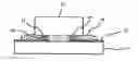
FIG. 1 is a sectional view illustrating a sea-island model including an epoxy compound sea part and acrylic resin island parts.
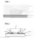
FIG. 2 is a sectional view of an example light-emitting device.
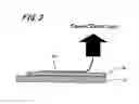
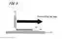
FIG. 3 is a sectional view illustrating the outline of a 90° peel strength test.
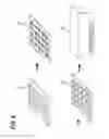
FIG. 4 illustrates a process of fabricating mounted LED samples.
FIG. 5 is a sectional view illustrating the outline of a die shear strength test.
DESCRIPTION OF EMBODIMENTS
An embodiment of the present invention (hereinafter referred to as “the present embodiment”) will now be described in detail with reference to the drawings in the following order. It should be appreciated, however, that the invention is not limited to the following embodiment; various modifications are possible without departing from the spirit of the invention. The drawings are schematic and not necessarily drawn to scale, and the specific sizes of the elements, for example, should be determined based on the following description. It should also be appreciated that the dimensional relationship and proportion of the elements may differ in different figures.
1. Adhesive
2. Light-Emitting Device
3. Examples
1. ADHESIVE
An adhesive according to the present invention contains an alicyclic epoxy compound or hydrogenated epoxy compound, a cationic catalyst, and an acrylic resin having a weight average molecular weight of 50,000 to 900,000. The acrylic resin contains 0.5% to 10% by weight of acrylic acid and 0.5% to 10% by weight of a hydroxyl-group-containing acrylic acid ester.
FIG. 1 is a sectional view of an interface between the adhesive and an oxide film, illustrating a sea-island model including an epoxy compound sea part and acrylic resin island parts. This sea-island model is a cured product model illustrating the state where acrylic resin island parts 13 dispersed in an epoxy compound sea part 12 are in contact with an oxide film 11a on wiring 11.
In this cured product model, the acrylic acid in the acrylic resin reacts with the epoxy compound to form links between the acrylic resin island parts 13 and the epoxy compound sea part 12 and also roughens the surface of the oxide film 11a to enhance the anchoring effect on the epoxy compound sea part 12. The hydroxyl-group-containing acrylic acid ester in the acrylic resin also produces electrostatic adhesion to the wiring 11 due to the polarity of the hydroxyl groups. In this way, the entire cured product of the acrylic resin island parts 13 and the epoxy compound sea part 12 can be bonded to the oxide film 11a, thus providing excellent adhesive strength.
Preferred alicyclic epoxy compounds include those having two or more epoxy groups in the molecule. Both liquid alicyclic epoxy compounds and solid alicyclic epoxy compounds may be used. Examples of alicyclic epoxy compounds include 3,4-epoxycyclohexenylmethyl 3′,4′-epoxycyclohexenecarboxylate and glycidyl hexahydrobisphenol A. Among these, 3,4-epoxycyclohexenylmethyl 3′,4′-epoxycyclohexenecarboxylate is preferred since it forms a cured product with optical transparency suitable for applications such as the mounting of LED elements and also has fast-curing properties.
Examples of hydrogenated epoxy compounds that can be used include hydrogenated products of alicyclic epoxy compounds as described above and known hydrogenated epoxy compounds such as hydrogenated bisphenol A epoxy compounds and hydrogenated bisphenol F epoxy compounds.
The alicyclic epoxy compounds and the hydrogenated epoxy compounds may be used alone or in combination. These epoxy compounds may be used in combination with other epoxy compounds, provided that they do not interfere with the advantages of the present invention. Examples of such epoxy compounds include known epoxy resins such as glycidyl ethers obtained by reacting, with epichlorohydrin, polyhydric phenols such as bisphenol A, bisphenol F, bisphenol S, tetramethylbisphenol A, diarylbisphenol A, hydroquinone, catechol, resorcinol, cresol, tetrabromobisphenol A, trihydroxybiphenyl, benzophenone, bisresorcinol, bisphenol hexafluoroacetone, tetramethylbisphenol A, tetramethylbisphenol F, tris(hydroxyphenyl)methane, bixylenol, phenol novolac, and cresol novolac; polyglycidyl ethers obtained by reacting, with epichlorohydrin, aliphatic polyhydric alcohols such as glycerol, neopentyl glycol, ethylene glycol, propylene glycol, tylene glycol, hexylene glycol, polyethylene glycol, and polypropylene glycol; glycidyl ether esters obtained by reacting, with epichlorohydrin, hydroxycarboxylic acids such as p-oxybenzoic acid and β-oxynaphthoic acid; polyglycidyl esters obtained from polycarboxylic acids such as phthalic acid, methylphthalic acid, isophthalic acid, terephthalic acid, tetrahydrophthalic acid, endomethylenetetrahydrophthalic acid, endomethylenehexahydrophthalic acid, trimellitic acid, and polymeric fatty acids; glycidylaminoglycidyl ethers obtained from aminophenols and aminoalkylphenols; glycidylaminoglycidyl esters obtained from aminobenzoic acids; glycidylamines obtained from compounds such as aniline, toluidine, tribromoaniline, xylylenediamine, diaminocyclohexane, bisaminomethylcyclohexane, 4,4′-diaminodiphenylmethane, and 4,4′-diaminodiphenylsulfone; and epoxylated polyolefins.
Examples of cationic catalysts that can be used include latent cationic curing agents such as aluminum chelate latent curing agents, imidazole latent curing agents, and sulfonium latent curing agents. Among these, aluminum chelate latent curing agents are preferred for their fast-curing properties.
The cationic catalyst is preferably present in an amount of 0.1 to 30 parts by mass, more preferably 0.5 to 20 parts by mass, per 100 parts by weight of the epoxy compound. If the cationic catalyst is present in insufficient amounts, the adhesive loses its reactivity. If the cationic catalyst is present in excess amounts, the adhesive tends to have a shorter product life.
The acrylic resin has a weight average molecular weight of 50,000 to 900,000. There is a correlation between the weight average molecular weight of the acrylic resin and the size of the acrylic resin island parts 13 in the cured product model shown in FIG. 1. If the acrylic resin has a weight average molecular weight of 50,000 to 900,000, acrylic resin island parts 13 of suitable size can be brought into contact with the oxide film 11a. If the acrylic resin has a weight average molecular weight of less than 50,000, the acrylic resin island parts 13 have a limited contact area with the oxide film 11a and thus fail to provide the effect of improving the adhesive strength. If the acrylic resin has a weight average molecular weight of more than 900,000, large acrylic resin island parts 13 are formed, which would not allow the entire cured product of the acrylic resin island parts 13 and the epoxy compound sea part 12 to be bonded to the oxide film 11a, thus resulting in decreased adhesive strength.
Acrylic acid is present in the acrylic resin in an amount of 0.5% to 10% by weight, preferably 1 to 5% by weight. If acrylic acid is present in the acrylic resin in an amount of 0.5% to 10% by weight, it reacts with the epoxy compound to form links between the acrylic resin island parts 13 and the epoxy compound sea part 12 and also roughens the surface of the oxide film 11a to enhance the anchoring effect on the epoxy compound sea part 12.
The hydroxyl-group-containing acrylic acid ester is present in the acrylic resin in an amount of 0.5% to 10% by weight, preferably 1% to 5% by weight. If the hydroxyl-group-containing acrylic acid ester is present in the acrylic resin in an amount of 0.5% to 10% by weight, it produces electrostatic adhesion to the wiring 11 due to the polarity of the hydroxyl groups.
The hydroxyl-group-containing acrylic acid ester may be at least one acrylic acid ester selected from the group consisting of 2-hydroxyethyl methacrylate, 2-hydroxypropyl methacrylate, 2-hydroxyethyl acrylate, and 2-hydroxypropyl acrylate. Among these, 2-hydroxyethyl methacrylate is preferred for its excellent adhesion to oxide films.
In addition to acrylic acid and the hydroxyl-group-containing acrylic acid ester, the acrylic resin contains an acrylic acid ester containing no hydroxy group. Examples of acrylic acid esters containing no hydroxy group include butyl acrylate, ethyl acrylate, and acrylonitrile. Preferably, the acrylic resin contains at least one acrylic ester selected from butyl acrylate, ethyl acrylate, and acrylonitrile.
The acrylic resin is preferably present in an amount of 1 to 10 parts by mass, more preferably 1 to 5 parts by mass, per 100 parts by mass of the epoxy compound. If the acrylic resin is present in an amount of 1 to 10 parts by mass per 100 parts by mass of the epoxy compound, the acrylic resin island parts 12 in the resulting cured product are dispersed at an appropriate density in the epoxy compound sea part 13.
The adhesive according to the present invention may further contain, as another component, a silane coupling agent for improving the interfacial adhesion to inorganic materials. Examples of silane coupling agents include epoxy, methacryloxy, amino, vinyl, mercapto/sulfide, and ureide silane coupling agents. These silane coupling agents may be used alone or in combination. Among these, epoxy silane coupling agents are preferred in the present embodiment.
The adhesive may further contain an inorganic filler for controlling the flowability and thereby improving the particle capture performance. Examples of inorganic fillers include, but not limited to, silica, talc, titanium oxide, calcium carbonate, and magnesium oxide. These inorganic fillers may optionally be used to alleviate the stress on connection structures in which connections are made by the adhesive. The adhesive may further contain other ingredients such as thermoplastic resins and softeners such as rubbers.
This adhesive provides high adhesive strength to metals that are not suitable for bonding, including aluminum.
The adhesive may be an anisotropic conductive adhesive containing conductive particles. The conductive particles may be known conductive particles. Examples of conductive particles include particles of various metals such as nickel, iron, copper, aluminum, tin, lead, chromium, cobalt, silver, and gold and alloys thereof; metal-coated particles of materials such as metal oxides, carbon, graphite, glass, ceramics, and plastics; and those further coated with insulating thin films. If the conductive particles are metal-coated resin particles, resin particles such as epoxy, phenolic, acrylic, acrylonitrile-styrene (AS), benzoguanamine, divinylbenzene, and styrene resin particles may be used.
The average particle size of the conductive particles is typically 1 to 10 μm, preferably 2 to 6 μm. The average particle density of the conductive particles in the adhesive is preferably 1,000 to 100,000 particles/mm2, more preferably 30,000 to 80,000 particles/mm2, for reasons of connection reliability and insulation reliability.
This anisotropic conductive adhesive provides high connection reliability for aluminum wiring and ITO wiring covered with oxide films.
2. LIGHT-EMITTING DEVICE
A light-emitting device according to the present invention will now be described. FIG. 2 is a sectional view of an example light-emitting device. The light-emitting device includes a substrate 21 having a wiring pattern 22, an anisotropic conductive film 30 formed on the electrodes of the wiring pattern 22, and a light-emitting element 23 mounted on the anisotropic conductive film 30. The anisotropic conductive film 30 is made of a cured product of the anisotropic conductive adhesive described above. The light-emitting device is obtained by applying the anisotropic conductive adhesive described above between the wiring pattern 22 on the substrate 21 and connection bumps 26 formed on an n-electrode 24 and a p-electrode 25 of an LED element serving as the light-emitting element 23 and then flip-chip mounting the light-emitting element 23 on the substrate 21.
In the present embodiment, the anisotropic conductive adhesive described above allows the effective use of substrates having wiring patterns made of aluminum. This results in a reduction in the cost of LED products.
The anisotropic conductive adhesive also allows the effective use of transparent substrates having wiring patterns made of transparent conductive films such as ITO films. For example, the anisotropic conductive adhesive can be used to mount LEDs on polyethylene terephthalate (PET) transparent substrates having indium tin oxide (ITO) wiring formed thereon.
Optionally, the LED 23 may be sealed with a transparent mold resin by covering the entire LED 23 with the resin. The LED 23 may further include a light reflective layer. Known light-emitting elements other than LEDs may also be used, provided that they do not interfere with the advantages of the present invention.
3. EXAMPLES
Examples
Examples of the present invention will now be described. In these examples, various anisotropic conductive adhesives were prepared and evaluated for their color, total reflectance, and peel strength. Mounted LED samples were also fabricated by mounting LED chips on substrates using the anisotropic conductive adhesives and were evaluated for their die shear strength and conduction resistance. It should be noted, however, that these examples are not intended to limit the invention.
[Evaluation of Color]
The anisotropic conductive adhesives were applied to a thickness of 100 μm on white ceramic sheets and were cured by heating at 180° C. for 30 seconds. The cured coatings were tested for their whiteness using a colorimeter (JIS P 8148). Coatings having a whiteness of 70% or more were evaluated as “white”. Coatings having a whiteness of less than 70% were evaluated for their color by visual inspection.
[Measurement of Total Reflectance]
The anisotropic conductive adhesives were applied to a thickness of 100 μm on white ceramic sheets and were cured by heating at 180° C. for 30 seconds. The cured coatings were tested for their total reflectance (specular reflection and diffused reflection) for light at a wavelength of 460 nm relative to that of barium sulfate using a spectrophotometer (UV3100, Shimadzu Corporation). The cured coatings were also tested for their total reflectance for light at a wavelength of 460 nm after a heat resistance test at 100° C. for 1,000 hours. A light reflectance of more than 30% is desirable in practical use.
[Measurement of Peel Strength]
The anisotropic conductive adhesives were applied to a thickness of 100 μm on white ceramic sheets. Aluminum pieces having a size of 1.5 mm×10 mm were then bonded to the sheets by heat pressing at 180° C. and 1.5 N for 30 seconds.
As shown in FIG. 3, an aluminum piece 42 was stripped from the sheet at a tensile rate of 50 mm/sec in the 90° Y-axis direction using a Tensilon tester. The maximum peel strength required to strip the aluminum piece 42 was measured.
[Fabrication of Mounted LED Sample]
Mounted LED samples were fabricated as shown in FIG. 4. A plurality of wiring substrates (50 μm Al wiring-25 μm polyimide (PI) layer-50 μm Al base) 51 with a pitch of 50 μm were arranged on a stage and were coated with about 10 μg of an anisotropic conductive adhesive 50. LED chips available from Cree, Inc. (trade name: DA3547, maximum rated current: 150 mA, size: 0.35 mm×0.46 mm) 52 were mounted on the anisotropic conductive adhesive 50 by flip chip mounting using a heat pressing tool 53 to obtain mounted LED samples.
The wiring substrate used in Example 5 had an ITO wiring pattern with a pitch of 50 μm (50 μm ITO wiring-25 μm polyimide (PI) layer-50 μm Al base).
[Measurement of Die Shear Strength]
As shown in FIG. 5, the mounted LED samples were tested for their bonding strength at 25° C. using a die shear tester. The shear rate of a tool 54 was 20 μm/sec.
[Evaluation of Conduction Resistance]
The mounted LED samples were tested for their initial conduction resistance, conduction resistance after a temperature cycle test (TCT), conduction resistance after an environmental test at 100° C. for 1,000 hours, and conduction resistance after an environmental test at 60° C. and 90% RH for 500 hours. In the temperature cycle test, the conduction resistance of the mounted LED samples was measured after 100, 500, and 1,000 temperature cycles, each cycle including 30 minutes of exposure to an atmosphere at −40° C. and 30 minutes of exposure to an atmosphere at 100° C. The conduction resistance was evaluated based on the Vf measured at an If of 50 mA. Mounted LED samples that exhibited an increase in Vf of less than 5% from the Vf in the test result table were rated as “good”. Mounted LED samples that exhibited an increase in Vf of 5% or more from the Vf in the test result table were rated as “poor”.
[Overall Evaluation]
Anisotropic conductive adhesives that were white, that had a total reflectance of 70% or more both initially and after an environmental test at 100° C. for 1,000 hours, a peel strength of 2.0 N or more both initially and after an environmental test at 60° C. and 90% RH for 500 hours, and a die shear strength of 5.0 N or more both initially and after an environmental test at 60° C. and 90% RH for 500 hours, and that were rated as “good” for all conductivity evaluations were rated as “good”. Others were rated as “poor”.
Example 1
An anisotropic conductive adhesive was prepared by dispersing 10 parts by mass of conductive particles (AUL704, Sekisui Chemical Co., Ltd.) in an adhesive containing 100 parts by mass of an alicyclic epoxy compound (Celloxide 2021P, Daicel Corporation), 5 parts by mass of a latent cationic curing agent (aluminum chelate latent curing agent), and 3 parts by mass of an acrylic resin (butyl acrylate (BA): 15%, ethyl acrylate (EA): 63%, acrylonitrile (AN): 20%, acrylic acid (AA): 1 w %, 2-hydroxyethyl methacrylate (HEMA): 1 wt %, weight average molecular weight Mw: 700,000). A mounted LED sample was fabricated by curing the anisotropic conductive adhesive at 180° C. and 1.5 N for 30 seconds.
Table 1 shows the evaluation results for Example 1. The anisotropic conductive adhesive was white and had an initial total reflectance of 75% and a total reflectance of 74% after an environmental test at 100° C. for 1,000 hours. The anisotropic conductive adhesive also had an initial peel strength of 4.0 N and a peel strength of 4.1 N after an environmental test at 60° C. and 90% RH for 500 hours. The mounted LED sample had an initial die shear strength of 8.5 N and a die shear strength of 5.3 N after an environmental test at 60° C. and 90% RH for 500 hours. The mounted LED sample was rated as “good” for initial conductivity evaluation, as “good” for conductivity evaluation after 100 cycles in a temperature cycle test, as “good” for conductivity evaluation after 500 cycles in a temperature cycle test, and as “good” for conductivity evaluation after 1,000 cycles in a temperature cycle test. The mounted LED sample was rated as “good” for conductivity evaluation after an environmental test at 100° C. for 1,000 hours and as “good” for conductivity evaluation after an environmental test at 60° C. and 90% RH for 500 hours. The overall evaluation was “good”.
Example 2
An anisotropic conductive adhesive was prepared as in Example 1 except that the acrylic resin had a weight average molecular weight Mw of 500,000 and was used to obtain a mounted LED sample.
Table 1 shows the evaluation results for Example 2. The anisotropic conductive adhesive was white and had an initial total reflectance of 73% and a total reflectance of 73% after an environmental test at 100° C. for 1,000 hours. The anisotropic conductive adhesive also had an initial peel strength of 3.1 N and a peel strength of 2.9 N after an environmental test at 60° C. and 90% RH for 500 hours. The mounted LED sample had an initial die shear strength of 7.8 N and a die shear strength of 7.6 N after an environmental test at 60° C. and 90% RH for 500 hours. The mounted LED sample was rated as “good” for initial conductivity evaluation, as “good” for conductivity evaluation after 100 cycles in a temperature cycle test, as “good” for conductivity evaluation after 500 cycles in a temperature cycle test, and as “good” for conductivity evaluation after 1,000 cycles in a temperature cycle test. The mounted LED sample was rated as “good” for conductivity evaluation after an environmental test at 100° C. for 1,000 hours and as “good” for conductivity evaluation after an environmental test at 60° C. and 90% RH for 500 hours. The overall evaluation was “good”.
Example 3
An anisotropic conductive adhesive was prepared as in Example 1 except that the acrylic resin had a weight average molecular weight Mw of 200,000 and was used to obtain a mounted LED sample.
Table 1 shows the evaluation results for Example 3. The anisotropic conductive adhesive was white and had an initial total reflectance of 75% and a total reflectance of 74% after an environmental test at 100° C. for 1,000 hours. The anisotropic conductive adhesive also had an initial peel strength of 3.5 N and a peel strength of 3.1 N after an environmental test at 60° C. and 90% RH for 500 hours. The mounted LED sample had an initial die shear strength of 7.5 N and a die shear strength of 7.6 N after an environmental test at 60° C. and 90% RH for 500 hours. The mounted LED sample was rated as “good” for initial conductivity evaluation, as “good” for conductivity evaluation after 100 cycles in a temperature cycle test, as “good” for conductivity evaluation after 500 cycles in a temperature cycle test, and as “good” for conductivity evaluation after 1,000 cycles in a temperature cycle test. The mounted LED sample was rated as “good” for conductivity evaluation after an environmental test at 100° C. for 1,000 hours and as “good” for conductivity evaluation after an environmental test at 60° C. and 90% RH for 500 hours. The overall evaluation was “good”.
Example 4
An anisotropic conductive adhesive was prepared as in Example 1 except that the acrylic resin had a weight average molecular weight Mw of 50,000 and was used to obtain a mounted LED sample.
Table 1 shows the evaluation results for Example 4. The anisotropic conductive adhesive was white and had an initial total reflectance of 71% and a total reflectance of 71% after an environmental test at 100° C. for 1,000 hours. The anisotropic conductive adhesive also had an initial peel strength of 3.8 N and a peel strength of 3.3 N after an environmental test at 60° C. and 90% RH for 500 hours. The mounted LED sample had an initial die shear strength of 6.9 N and a die shear strength of 7.1 N after an environmental test at 60° C. and 90% RH for 500 hours. The mounted LED sample was rated as “good” for initial conductivity evaluation, as “good” for conductivity evaluation after 100 cycles in a temperature cycle test, as “good” for conductivity evaluation after 500 cycles in a temperature cycle test, and as “good” for conductivity evaluation after 1,000 cycles in a temperature cycle test. The mounted LED sample was rated as “good” for conductivity evaluation after an environmental test at 100° C. for 1,000 hours and as “good” for conductivity evaluation after an environmental test at 60° C. and 90% RH for 500 hours. The overall evaluation was “good”.
Example 5
A mounted LED sample was fabricated as in Example 1 except that the wiring substrate had ITO wiring with a pitch of 50 μm (50 μm ITO wiring-25 μm polyimide (PI) layer-50 μm Al base).
Table 1 shows the evaluation results for Example 5. The anisotropic conductive adhesive was white and had an initial total reflectance of 75% and a total reflectance of 74% after an environmental test at 100° C. for 1,000 hours. In the measurement of die shear strength, the mounted LED sample failed at the interface between the ITO and the substrate and had good adhesive strength between the adhesive and the ITO. The mounted LED sample was rated as “good” for initial conductivity evaluation, as “good” for conductivity evaluation after 100 cycles in a temperature cycle test, as “good” for conductivity evaluation after 500 cycles in a temperature cycle test, and as “good” for conductivity evaluation after 1,000 cycles in a temperature cycle test. The mounted LED sample was rated as “good” for conductivity evaluation after an environmental test at 60° C. and 90% RH for 500 hours. The overall evaluation was “good”.
Comparative Example 1
An anisotropic conductive adhesive was prepared as in Example 1 except that the acrylic resin had a weight average molecular weight Mw of 200,000 and contained 0% by weight of acrylic acid (AA) (BA: 15%, EA: 64%, AN: 20%, AA: 0 w %, HEMA: 1 wt %, Mw: 200,000) and was used to obtain a mounted LED sample.
Table 1 shows the evaluation results for Comparative Example 1. The anisotropic conductive adhesive was white and had an initial total reflectance of 73% and a total reflectance of 72% after an environmental test at 100° C. for 1,000 hours. The anisotropic conductive adhesive also had an initial peel strength of 0.9 N and a peel strength of 1.1 N after an environmental test at 60° C. and 90% RH for 500 hours. The mounted LED sample had an initial die shear strength of 6.1 N and a die shear strength of 5.3 N after an environmental test at 60° C. and 90% RH for 500 hours. The mounted LED sample was rated as “good” for initial conductivity evaluation, as “good” for conductivity evaluation after 100 cycles in a temperature cycle test, as “poor” for conductivity evaluation after 500 cycles in a temperature cycle test, and as “poor” for conductivity evaluation after 1,000 cycles in a temperature cycle test. The mounted LED sample was rated as “good” for conductivity evaluation after an environmental test at 100° C. for 1,000 hours and as “good” for conductivity evaluation after an environmental test at 60° C. and 90% RH for 500 hours. The overall evaluation was “poor”.
Comparative Example 2
An anisotropic conductive adhesive was prepared as in Example 1 except that the acrylic resin had a weight average molecular weight Mw of 200,000 and contained 0% by weight of acrylic acid (AA) and 0% by weight of 2-hydroxyethyl methacrylate (HEMA) (BA: 15%, EA: 65%, AN: 20%, AA: 0 w %, HEMA: 0 wt %, Mw: 200,000) and was used to obtain a mounted LED sample.
Table 1 shows the evaluation results for Comparative Example 2. The anisotropic conductive adhesive was white and had an initial total reflectance of 74% and a total reflectance of 74% after an environmental test at 100° C. for 1,000 hours. The anisotropic conductive adhesive also had an initial peel strength of less than 0.5 N and a peel strength of less than 0.5 N after an environmental test at 60° C. and 90% RH for 500 hours. The mounted LED sample had an initial die shear strength of 4.5 N and a die shear strength of 3.9 N after an environmental test at 60° C. and 90% RH for 500 hours. The mounted LED sample was rated as “good” for initial conductivity evaluation, as “good” for conductivity evaluation after 100 cycles in a temperature cycle test, as “poor” for conductivity evaluation after 500 cycles in a temperature cycle test, and as “poor” for conductivity evaluation after 1,000 cycles in a temperature cycle test. The mounted LED sample was rated as “good” for conductivity evaluation after an environmental test at 100° C. for 1,000 hours and as “good” for conductivity evaluation after an environmental test at 60° C. and 90% RH for 500 hours. The overall evaluation was “poor”.
Comparative Example 3
An anisotropic conductive adhesive was prepared by dispersing 10 parts by mass of conductive particles (AUL704, Sekisui Chemical Co., Ltd.) in an adhesive containing 50 parts by mass of an alicyclic epoxy compound (Celloxide 2021P, Daicel Corporation), 40 parts by mass of an acid anhydride curing agent (methylhexahydrophthalic anhydride), and 3 parts by mass of an acrylic resin (BA: 15%, EA: 63%, AN: 20%, AA: 1 w %, HEMA: 1 wt %, Mw: 700,000). A mounted LED sample was fabricated by curing the anisotropic conductive adhesive at 230° C. and 1.5 N for 30 seconds.
Table 1 shows the evaluation results for Comparative Example 3. The anisotropic conductive adhesive was white and had an initial total reflectance of 75% and a total reflectance of 75% after an environmental test at 100° C. for 1,000 hours. The anisotropic conductive adhesive also had an initial peel strength of 1.6 N and a peel strength of 1.3 N after an environmental test at 60° C. and 90% RH for 500 hours. The mounted LED sample had an initial die shear strength of 7.2 N and a die shear strength of 6.3 N after an environmental test at 60° C. and 90% RH for 500 hours. The mounted LED sample was rated as “good” for initial conductivity evaluation, as “poor” for conductivity evaluation after 100 cycles in a temperature cycle test, as “poor” for conductivity evaluation after 500 cycles in a temperature cycle test, and as “poor” for conductivity evaluation after 1,000 cycles in a temperature cycle test. The mounted LED sample was rated as “good” for conductivity evaluation after an environmental test at 100° C. for 1,000 hours and as “poor” for conductivity evaluation after an environmental test at 60° C. and 90% RH for 500 hours. The overall evaluation was “poor”.
Comparative Example 4
An anisotropic conductive adhesive was prepared as in Comparative Example 3 except that the acrylic resin had a weight average molecular weight Mw of 200,000 and contained 0% by weight of acrylic acid (AA) and 0% by weight of 2-hydroxyethyl methacrylate (HEMA) (BA: 15%, EA: 65%, AN: 20%, AA: 0 w %, HEMA: 0 wt %, Mw: 200,000) and was used to obtain a mounted LED sample.
Table 1 shows the evaluation results for Comparative Example 4. The anisotropic conductive adhesive was white and had an initial total reflectance of 77% and a total reflectance of 77% after an environmental test at 100° C. for 1,000 hours. The anisotropic conductive adhesive also had an initial peel strength of less than 0.5 N and a peel strength of less than 0.5 N after an environmental test at 60° C. and 90% RH for 500 hours. The mounted LED sample had an initial die shear strength of 3.8 N and a die shear strength of 3.2 N after an environmental test at 60° C. and 90% RH for 500 hours. The mounted LED sample was rated as “good” for initial conductivity evaluation, as “poor” for conductivity evaluation after 100 cycles in a temperature cycle test, as “poor” for conductivity evaluation after 500 cycles in a temperature cycle test, and as “poor” for conductivity evaluation after 1,000 cycles in a temperature cycle test. The mounted LED sample was rated as “good” for conductivity evaluation after an environmental test at 100° C. for 1,000 hours and as “poor” for conductivity evaluation after an environmental test at 60° C. and 90% RH for 500 hours. The overall evaluation was “poor”.
Comparative Example 5
An anisotropic conductive adhesive was prepared as in Example 1 except that the alicyclic epoxy compound was replaced with 100 parts by mass of a cycloolefin and was used to obtain a mounted LED sample. The mounted LED sample was fabricated by curing the anisotropic conductive adhesive at 180° C. and 1.5 N for 240 seconds.
Table 1 shows the evaluation results for Comparative Example 5. The anisotropic conductive adhesive was yellow and had an initial total reflectance of 61% and a total reflectance of 32% after an environmental test at 100° C. for 1,000 hours. The anisotropic conductive adhesive also had an initial peel strength of 1.2 N and a peel strength of 1.4 N after an environmental test at 60° C. and 90% RH for 500 hours. The mounted LED sample had an initial die shear strength of 7.2 N and a die shear strength of 6.5 N after an environmental test at 60° C. and 90% RH for 500 hours. The mounted LED sample was rated as “good” for initial conductivity evaluation, as “poor” for conductivity evaluation after 100 cycles in a temperature cycle test, as “poor” for conductivity evaluation after 500 cycles in a temperature cycle test, and as “poor” for conductivity evaluation after 1,000 cycles in a temperature cycle test. The mounted LED sample was rated as “good” for conductivity evaluation after an environmental test at 100° C. for 1,000 hours and as “good” for conductivity evaluation after an environmental test at 60° C. and 90% RH for 500 hours. The overall evaluation was “poor”.
Comparative Example 6
An anisotropic conductive adhesive was prepared as in Example 1 except that the alicyclic epoxy compound was replaced with a bisphenol F epoxy compound, the latent cationic curing agent was replaced with an anionic curing agent (amine curing agent), and no acrylic resin was added. The anisotropic conductive adhesive was used to obtain a mounted LED sample. The mounted LED sample was fabricated by curing the anisotropic conductive adhesive at 150° C. and 1.5 N for 30 seconds.
Table 1 shows the evaluation results for Comparative Example 6. The anisotropic conductive adhesive was yellow and had an initial total reflectance of 58% and a total reflectance of 15% after an environmental test at 100° C. for 1,000 hours. The anisotropic conductive adhesive also had an initial peel strength of 1.4 N and a peel strength of less than 0.1 N after an environmental test at 60° C. and 90% RH for 500 hours. The mounted LED sample had an initial die shear strength of 6.8 N and a die shear strength of 1.1 N after an environmental test at 60° C. and 90% RH for 500 hours. The mounted LED sample was rated as “good” for initial conductivity evaluation, as “good” for conductivity evaluation after 100 cycles in a temperature cycle test, as “poor” for conductivity evaluation after 500 cycles in a temperature cycle test, and as “poor” for conductivity evaluation after 1,000 cycles in a temperature cycle test. The mounted LED sample was rated as “good” for conductivity evaluation after an environmental test at 100° C. for 1,000 hours and as “poor” for conductivity evaluation after an environmental test at 60° C. and 90% RH for 500 hours. The overall evaluation was “poor”.
Comparative Example 7
An anisotropic conductive adhesive was prepared as in Comparative Example 6 except that an acrylic resin (BA: 15%, EA: 63%, AN: 20%, AA: 1 w %, HEMA: 1 wt %, Mw: 700,000) was added in an amount of 3 parts by mass and was used to obtain a mounted LED sample.
Table 1 shows the evaluation results for Comparative Example 7. The anisotropic conductive adhesive was yellow and had an initial total reflectance of 53% and a total reflectance of 11% after an environmental test at 100° C. for 1,000 hours. The anisotropic conductive adhesive also had an initial peel strength of 2.5 N and a peel strength of less than 0.1 N after an environmental test at 60° C. and 90% RH for 500 hours. The mounted LED sample had an initial die shear strength of 7.1 N and a die shear strength of 0.4 N after an environmental test at 60° C. and 90% RH for 500 hours. The mounted LED sample was rated as “good” for initial conductivity evaluation, as “good” for conductivity evaluation after 100 cycles in a temperature cycle test, as “good” for conductivity evaluation after 500 cycles in a temperature cycle test, and as “poor” for conductivity evaluation after 1,000 cycles in a temperature cycle test. The mounted LED sample was rated as “good” for conductivity evaluation after an environmental test at 100° C. for 1,000 hours and as “poor” for conductivity evaluation after an environmental test at 60° C. and 90% RH for 500 hours. The overall evaluation was “poor”.
| TABLE 1 | |||||||||||||
| Compa- | Compa- | Compa- | Compa- | Compa- | Compa- | Compa- | |||||||
| rative | rative | rative | rative | rative | rative | rative | |||||||
| Ex- | Ex- | Ex- | Ex- | Ex- | Ex- | Ex- | Ex- | Ex- | Ex- | Ex- | Ex- | ||
| ample | ample | ample | ample | ample | ample | ample | ample | ample | ample | ample | ample | ||
| 1 | 2 | 3 | 4 | 5 | 1 | 2 | 3 | 4 | 5 | 6 | 7 | ||
| Base | Alicyclic epoxy | 100 | 100 | 100 | 100 | 100 | 100 | 100 | 50 | 50 | — | — | — |
| Cycloolefin | — | — | — | — | — | — | — | — | — | 100 | — | — | |
| Bisphenol F | — | — | — | — | — | — | — | — | — | — | 100 | 100 | |
| epoxy | |||||||||||||
| Curing agent | Latent cationic | 5 | 5 | 5 | 5 | 5 | 5 | 5 | — | — | 5 | — | — |
| curing agent | |||||||||||||
| Anionic curing | — | — | — | — | — | — | — | — | — | — | 5 | 5 | |
| agent | |||||||||||||
| Acid anhydride | — | — | — | — | — | — | — | 40 | 40 | — | — | — | |
| curing agent | |||||||||||||
| Acrylic resin | AA: 1 wt %, | 3 | — | — | — | 3 | — | — | 3 | — | 3 | — | 3 |
| HEMA: 1 wt % | |||||||||||||
| Mw: 700,000 | |||||||||||||
| AA: l wt %, | — | 3 | — | — | — | — | — | — | — | — | — | — | |
| HEMA: 1 wt % | |||||||||||||
| Mw: 500,000 | |||||||||||||
| AA: 1 wt %, | — | — | 3 | — | — | — | — | — | — | — | — | — | |
| HEMA: 1 wt % | |||||||||||||
| Mw: 200,000 | |||||||||||||
| AA: 1 wt %, | — | — | — | 3 | — | — | — | — | — | — | — | — | |
| HEMA: 1 wt % | |||||||||||||
| Mw: 50,000 | |||||||||||||
| AA: 0 wt %, | — | — | — | — | — | 3 | — | — | — | — | — | — | |
| HEMA: 1 wt % | |||||||||||||
| Mw: 200,000 | |||||||||||||
| AA: 0 wt %, | — | — | — | — | — | — | 3 | — | 3 | — | — | — | |
| HEMA: 0 wt % | |||||||||||||
| Mw: 200,000 |
| Conductive particles | 10 | 10 | 10 | 10 | 10 | 10 | 10 | 10 | 10 | 10 | 10 | 10 |
| Color of anisotropic conductive | White | White | White | White | White | White | White | White | White | Yellow | Yellow | Yellow |
| adhesive |
| Total | Initial [%] | 75 | 73 | 75 | 71 | 75 | 73 | 74 | 75 | 77 | 61 | 58 | 53 |
| reflectance | 100° C., | 74 | 73 | 74 | 71 | 74 | 72 | 74 | 75 | 77 | 32 | 15 | 11 |
| 1000 h[%] | |||||||||||||
| Peel | Initial [N] | 4.0 | 3.1 | 3.5 | 3.8 | — | 0.9 | <0.5 | 1.6 | <0.5 | 1.2 | 1.4 | 2.5 |
| strength | 60° C., 90% Rh, | 4.1 | 2.9 | 3.1 | 3.3 | — | 1.1 | <0.5 | 1.3 | <0.5 | 1.4 | <0.1 | <0.1 |
| 500 h[N] | |||||||||||||
| Die shear | Initial [N] | 8.5 | 7.8 | 7.5 | 6.9 | Material | 6.1 | 4.5 | 7.2 | 3.8 | 7.2 | 6.8 | 7.1 |
| strength | failure | ||||||||||||
| 60° C., 90% Rh, | 5.3 | 7.6 | 7.6 | 7.1 | Material | 5.3 | 3.9 | 6.3 | 3.2 | 6.5 | 1.1 | 0.4 | |
| 500 h[N] | failure | ||||||||||||
| Conductivity | Initial | Good | Good | Good | Good | Good | Good | Good | Good | Good | Good | Good | Good |
| evaluation | TCT 100 cyc | Good | Good | Good | Good | Good | Good | Good | Poor | Poor | Poor | Good | Good |
| TCT 500 cyc | Good | Good | Good | Good | Good | Poor | Poor | Poor | Poor | Poor | Poor | Good | |
| TCT 1000 cyc | Good | Good | Good | Good | Good | Poor | Poor | Poor | Poor | Poor | Poor | Poor | |
| 100° C., 1000 h | Good | Good | Good | Good | — | Good | Good | Good | Good | Good | Good | Good | |
| 60° C., 90% Rh, | Good | Good | Good | Good | Good | Good | Good | Poor | Poor | Good | Poor | Poor | |
| 500 h | |||||||||||||
| Overall | Good | Good | Good | Good | Good | Poor | Poor | Poor | Poor | Poor | Poor | Poor | |
| evaluation | |||||||||||||
The anisotropic conductive adhesives of Comparative Examples 1 and 2, which contained an acrylic resin containing no acrylic acid (AA) or 2-hydroxyethyl methacrylate (HEMA), had low adhesive strength to aluminum and low conduction reliability.
The anisotropic conductive adhesives of Comparative Examples 3 and 4, which contained an acid anhydride curing agent, had low conduction reliability after an environmental test at 60° C. and 90% RH for 500 hours. A comparison between Comparative Examples 3 and 4 also shows that it is preferred to use an acrylic resin containing AA and HEMA, as in the comparison between Comparative Examples 1 and 2 and the Examples.
The anisotropic conductive adhesive of Comparative Example 5, which contained a cycloolefin base, reacted slowly and required an extended period of time for curing. This anisotropic conductive adhesive was not white because of the color of the resin itself and discoloration due to double bonds and also had low conduction reliability.
The anisotropic conductive adhesives of Comparative Examples 6 and 7 had adhesion to aluminum due to the polar effect of the amine curing agent. These anisotropic conductive adhesives, however, were susceptible to humidity and had low conduction reliability after an environmental test at 60° C. and 90% RH for 500 hours. The anisotropic conductive adhesives also had low whiteness because of the discoloration of the amine.
The anisotropic conductive adhesives of Examples 1 to 5, which contained an alicyclic epoxy compound, a latent cationic curing agent, and an acrylic resin containing acrylic acid (AA) and 2-hydroxyethyl methacrylate (HEMA), had properties suitable for optical applications and high adhesive strength and conduction reliability for aluminum wiring and ITO wiring covered with oxide films.
REFERENCE SIGNS LIST
11 wiring, 12 epoxy compound sea part, 13 acrylic resin island part, 21 substrate, 22 wiring pattern, 23 light-emitting element, 24 n-electrode, 25 p-electrode, 26 bump, 30 anisotropic conductive film, 50 anisotropic conductive adhesive, 51 wiring substrate, 52 LED chip, 53 heating tool, 54 tool
Claims
1. An adhesive comprising an alicyclic epoxy compound or hydrogenated epoxy compound, a cationic catalyst, and an acrylic resin having a weight average molecular weight of 50,000 to 900,000,
the acrylic resin comprising 0.5% to 10% by weight of acrylic acid and 0.5% to 10% by weight of a hydroxyl-group-containing acrylic acid ester.
2. The adhesive according to claim 1, wherein the acrylic resin is present in an amount of 1 to 10 parts by mass per 100 parts by mass of the epoxy compound.
3. The adhesive according to claim 1 or 2, wherein the hydroxyl-group-containing acrylic acid ester is at least one compound selected from the group consisting of 2-hydroxyethyl methacrylate, 2-hydroxypropyl methacrylate, 2-hydroxyethyl acrylate, and 2-hydroxypropyl acrylate.
4. The adhesive according to any one of claims 1 to 3, wherein the acrylic resin further comprises at least one acrylic acid ester selected from butyl acrylate, ethyl acrylate, and ethyl acrylate.
5. The adhesive according to any one of claims 1 to 4, wherein the cationic catalyst is an aluminum chelate latent curing agent.
6. The adhesive according to any one of claims 1 to 5, further comprising conductive particles.
7. A light-emitting device comprising:
a substrate having a wiring pattern comprising aluminum;
an anisotropic conductive film formed on an electrode of the wiring pattern; and
a light-emitting element mounted on the anisotropic conductive film,
the anisotropic conductive film comprising a cured product of an anisotropic conductive adhesive comprising an alicyclic epoxy compound or hydrogenated epoxy compound, a cationic catalyst, an acrylic resin having a weight average molecular weight of 50,000 to 900,000, and conductive particles, the acrylic resin comprising 0.5% to 10% by weight of acrylic acid and 0.5% to 10% by weight of a hydroxyl-group-containing acrylic acid ester.
8. A light-emitting device comprising:
a transparent substrate having a wiring pattern comprising a transparent conductive film;
an anisotropic conductive film formed on an electrode of the wiring pattern; and
a light-emitting element mounted on the anisotropic conductive film,
the anisotropic conductive film comprising a cured product of an anisotropic conductive adhesive comprising an alicyclic epoxy compound or hydrogenated epoxy compound, a cationic catalyst, an acrylic resin having a weight average molecular weight of 50,000 to 900,000, and conductive particles, the acrylic resin comprising 0.5% to 10% by weight of acrylic acid and 0.5% to 10% by weight of a hydroxyl-group-containing acrylic acid ester.
Images & Drawings included:
Sources:
- United States Patent and Trademark Office - verify current appl. status at the USPTO↗
Similar patent applications:
- » 20050167659
Organic adhesive light-emitting device with ohmic metal contact - » 20050184297
Organic adhesive light-emitting device with a vertical structure - » 20050194587
Organic adhesive light-emitting device with ohmic metal bulge - » 20130264602
LIGHT-REFLECTIVE ANISOTROPIC CONDUCTIVE ADHESIVE AND LIGHT-EMITTING DEVICE - » 20120193666
Light-reflective anisotropic conductive adhesive and light-emitting device - » 20130105841
LIGHT-REFLECTIVE CONDUCTIVE PARTICLE, ANISOTROPIC CONDUCTIVE ADHESIVE, AND LIGHT-EMITTING DEVICE - » 20120175660
Light-reflective conductive particle, anisotropic conductive adhesive and light-emitting device - » 20130087825
Light-reflective anisotropic conductive adhesive and light-emitting device - » 20140001419
Light-reflective anisotropic conductive adhesive and light-emitting device - » 20140103266
Light-reflective conductive particle, anisotropic conductive adhesive and light-emitting device
Recent applications in this class:
- » 20250207001 2025-06-26
Method of underwater bonding - » 20240240064 2024-07-18
TWO-PART CURABLE COMPOSITION - » 20220325148 2022-10-13
EASILY WATER-DISMANTLABLE ADHESIVE COMPOSITION - » 20160194530 2016-07-07
POLYMERIZABLE ADHESIVE THAT FORMS METHACRYLATE IPN - » 20090298969 2009-12-03
CYANOACRYLATE COMPOSITIONS CONTAINING DISPERSIONS OF CORE SHELL RUBBERS IN (METH)ACRYLATES - » 20070135574 2007-06-14
Sealing material for automobile door
Recent applications for this Assignee:
- » 20210388248 2021-12-16
Repairing material for liquid leakage, repairing method for liquid leakage, and pipeline - » 20210382214 2021-12-09
Optical filter and light-emitting device - » 20210382205 2021-12-09
LAMINATE, METHOD OF PRODUCING LAMINATE, METHOD OF FORMING OPTICAL BODY, AND CAMERA MODULE-EQUIPPED DEVICE - » 20210340037 2021-11-04
Anionic flocculant, anionic flocculant production method, and treatment method - » 20210272879 2021-09-02
Semiconductor device and method of producing the same - » 20210225777 2021-07-22
Semiconductor device and method of producing the same - » 20210214489 2021-07-15
Cationically curable composition and cured product production method - » 20210197505 2021-07-01
Display panel and optical film - » 20210189027 2021-06-24
RESIN PARTICLES AND METHOD FOR PRODUCING RESIN PARTICLES - » 20210132257 2021-05-06
Laminate, anti-reflection structure and camera module mounting apparatus