Pump Jack Pulley
US20160355384A1
2016-12-08
14/729,892
2015-06-03
Abstract:
With a pump jack pulley, contractors and employees would be able to load material onto the pulley and lift the material safely without putting a strain on their back. The pump jack pulley is very simple when it comes to design, but a high quality and reliable product. It can be manufactured for a fraction of the cost of the heavy machinery available, which would make it affordable and available to a wider range of construction laborers. This would allow for the product to be used throughout the full project, saving time and increasing efficiency.
Interested in similar patents?
Get notified when new applications in this technology area are published.
Classification:
B66D3/04 » CPC main
Portable or mobile lifting or hauling appliances Pulley blocks or like devices in which force is applied to a rope, cable, or chain which passes over one or more pulleys, e.g. to obtain mechanical advantage
Description
CROSS REFERENCE TO RELATED APPLICATIONS
Provisional Patent Application No. 62/009,067
STATEMENT REGARDING FEDERALLY SPONSORED RESEARCH OR DEVELOPMENT
Not Applicable
REFERENCE TO SEQUENCE LISTING, A TABLE, OR A COMPUTER PROGRAM
Not Applicable
INVENTION BACKGROUND
Field of Invention
The present invention is in the mechanical field, more specifically a device to lift items to various levels of scaffolding or other platforms.
Problems this Invention Resolves
Currently, employees carry material up to the scaffolding table using a ladder, which is time consuming and puts a lot of strain on the back. Forklifts and other lifting machinery are available to do the job, but these heavy machinery are expensive and are rarely used for material that can be carried up.
How the Problem was Resolved Before
Although lifting machinery is available, the expenses of such machinery prevent contractors and employees to rent them for construction projects and for the rare times that they are used, they are only rented for short periods of time and would not be available throughout most of the project.
Why the Invention is Novel and Superiority of the Technology used to Solve the Problem
For where there is scaffolding and the need to lift items to workers there is no crane that is inexpensive, simple to erect, and as portable as the present invention.
With a pump jack pulley, contractors and employees would be able to load material onto the pulley and lift the material safely without putting a strain on their back.
The pump jack pulley is very simple when it comes to design, but a high quality and reliable product. It can be manufactured for a fraction of the cost of the heavy machinery available, which would make it affordable and available to a wider range of construction laborers. This would allow for the product to be used throughout the full project, saving time and increasing efficiency.
Additional Benefits
This invention is simple to construct and can be used with or without a power assist.
INVENTION SUMMARY
The present invention is a pump jack pulley. It is used to carry tools and materials to scaffolding table without the use of a ladder, which minimizes the number of trips and eliminates wasted time. The heavy lifting of construction material also decreases the risk of back injuries on the job.
INVENTION DRAWINGS WITH NUMBERED COMPONENTS AND THEIR FUNCTIONALITY
Brief Description of Figures
FIG. 1—BACK STRUCTURAL BAR, SERVES AS BACKBONE THAT CONNECTS MAIN PARTS
PART: 1—BACK STRUCTURAL BAR
PART: 2—SUPPORT BAR
PART: 3—TOP WEIGHT HOLDING BAR
PART: 4—BOTTOM PULLEY STABILIZER YOKE
PART: 5—U SHAPE BRACE YOKE
FIG. 2—SUPPORT BAR, SERVES AS SUPPORT BETWEEN TOP WEIGHT HOLDING
BAR AND BACK STRUCTURAL BAR
PART: 1—BACK STRUCTURAL BAR
PART: 2—SUPPORT BAR
PART: 3—TOP WEIGHT HOLDING BAR
PART: 4—BOTTOM PULLEY STABILIZER YOKE
FIG. 3—TOP WEIGHT HOLDING BAR WORKS IN CONJUNCTION WITH TOP EXTENDING BAR TO EXTEND LENGTH, ONE MAIN HOLE ON THE TOP WEIGHT HOLDING BAR FEEDS LOCK PIN THROUGH TO SECURE EXTENDING BAR
PART: 1—BACK STRUCTURAL BAR
PART: 2—SUPPORT BAR
PART: 3—TOP WEIGHT HOLDING BAR
PART: 5—U SHAPE BRACE YOKE
FIG. 4—BOTTOM PULLEY STABILIZER YOKE, ATTACHED TO BACK STRUCTURAL BAR TO STABILIZE BOTTOM OF PULLEY
PART: 1—BACK STRUCTURAL BAR
PART: 2—SUPPORT BAR
PART: 4—BOTTOM PULLEY STABILIZER YOKE
FIG. 5—BRACE LATCHED TO THE YOKE, HOLDS PULLEY TO PUMP JACK POLE
PART: 5—U SHAPE BRACE YOKE
PART: 6—BRACE LATCH WITH SLOT THAT ALOWS TO INSERT IT INTO YOKE SLOT, LATCH TAB KEEPS FROM MOVING
PART: 7—HINGE BOLT
PART: 9—THREADED HAND KNOB TIGHTENING SCREW TO TIGHTEN BRACE AGAINST THE POLE PART: 10—THREADED BRACE BOLT TO ATTACH BRACE TO BACK STRUCTURAL BAR
PART: 11—BRACE NUT TO ATTACH BRACE TO BACK STRUCTURAL BAR
FIG. 6—UNLATCHED BRACE
PART: 5—U SHAPE BRACE YOKE
PART: 6—BRACE LATCH
PART: 7—HINGE BOLT
PART: 8—THREADED HAND KNOB NUT
PART: 9—THREADED HAND KNOB
PART: 10—BRACE BOLT TO ATTACH BRACE TO BACK STRUCTURAL BAR
PART: 11—BRACE NUT TO ATTACH BRACE TO BACK STRUCTURAL BAR
FIG. 7—BRACE U SHAPE YOKE WITH SLOT FOR LATCH TO INSERT AND SECURE THE LATCH, OPPOSITE SIDE OF THE SLOT HAS A LATCH HINGE
PART: 5—U SHAPE BRACE YOKE
FIG. 8—PULLEY FRAME THAT WOULD BE WELDED TOGETHER BY
MANUFACTURER
PART: 1—BACK STRUCTURAL BAR
PART: 2—SUPPORT BAR
PART: 3—TOP WEIGHT HOLDING BAR
PART: 4—BOTTOM PULLEY STABILIZER YOKE
PART: 5—U SHAPE BRACE YOKE
PART: 9—THREADED HAND KNOB
FIG. 9—LENGTH ADJUSTING BAR THAT WOULD BE WELDED TOGETHER BY MANUFACTURER
PART: 12—TOP EXTENDING BAR WITH FIVE HOLES TO ADJUST THE LENGTH
PART: 13—TRIANGULAR HOOK TO ATTACH PULLEY ROPE BLOCK
FIG. 10—SQUARE WIRE LOCK PIN, TO SECURE EXTENDING BAR ONCE LENGTH IS ADJUSTED
PART: 14—LOCK PIN
PART: 15—SQUARE WIRE
FIG. 11—LENGTH ADJUSTING BAR (FIG. 9) PLACED INTO TOP WEIGHT HOLDING
BAR AND LOCKED WITH SQUARE WIRE LOCK
PART: 1—BACK STRUCTURAL BAR
PART: 2—SUPPORT BAR
PART: 3—TOP WEIGHT HOLDING BAR
PART: 4—BOTTOM PULLEY STABILIZER YOKE
PART: 5—U SHAPE BRACE YOKE
PART: 9—THREADED HAND KNOB
PART: 12—TOP EXTENDING BAR
PART: 13—TRIANGULAR HOOK TO ATTACH PULLEY ROPE BLOCK
PART: 14—LOCK PIN
FIG. 12—PARTS OF PULLEY ROPE BLOCK
PART: 16—UPPER BOLT TO HOLD TOGETHER UPPER STRUCTURE AND BLOCK HOOK
PART: 17—BOTTOM BOLT TO HOLD TOGETHER BOTTOM STRUCTURE AND ROPE BLOCK WHEEL PART: 18—RIGHT STRUCTURE PLATE
PART: 19—CILINDER BOLT SPACER BETWEEN RIGHT AND LEFT PLATES
PART: 20—RIGHT SPACER, SITS BETWEEN RIGHT STRUCTURE PLATE AND ROPE BLOCK WHEEL
PART: 21—ROPE BLOCK WHEEL THAT ROTATES ROPE
PART: 22—BLOCK WHEEL BEARING
PART: 23—LEFT SPACER, SITS BETWEEN LEFT STRUCTURE PLATE AND ROPE BLOCK WHEEL
PART: 24—BLOCK HOOK
PART: 25—BLOCK HOOK LATCH THAT SECURES HOOK
PART: 26—BLOCK HOOK SPRING THAT RETURNS LATCH
PART: 27—BLOCK HOOK LOCK PIN
PART: 28—LEFT STRUCTURE PLATE
PART: 29—UPPER WASHER
PART: 30—UPPER LOCK NUT NYLON INSERT
PART: 31—BOTTOM WASHER
PART: 32—BOTTOM LOCK NUT NYLON INSERT
FIG. 13—DIFFERENT ANGLES OF PULLEY ROPE BLOCK AFTER IT IS ASSEMBLED BY MANUFACTURER
PART: 22—BLOCK WHEEL WITH BEARING
PART: 24—BLOCK HOOK
PART: 28—LEFT STRUCTURE PLATE
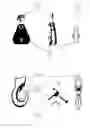
FIG. 14—3½-4LB SLIDING CHOKER HOOK WITH LATCH, RETURNS ROPE
PART: 33—BODY OF SLIDING CHOKER HOOK
PART: 34—CHOKER HOOK SPRING, TO RETRACT LATCH
PART: 35—CHOKER HOOK LATCH
PART: 36—CHOKER HOOK LOCK PIN
FIG. 15—MECHANISM THAT FEEDS ⅝ RAIDED POLY ROPE WITH LOOPED END THROUGH SLIDING CHOKER HOOK
PART: 33—BODY OF SLIDING CHOKER HOOK
PART: 37—⅝ RAIDED POLY ROPE WITH LOOPED END
PART: 38—CLAMP THAT HOLDS LOOP OF ROPE
FIG. 16—CHOCKER HOOK WITH ROPE IN FIG. 15 FEEDS THROUGH PULLEY ROPE BLOCK (FIG. 13)
PART: 24—BLOCK HOOK
PART: 33—BODY OF SLIDING CHOKER HOOK
PART: 37—⅝ RAIDED POLY ROPE WITH LOOPED END
PART: 38—CLAMP THAT HOLDS LOOP OF ROPE
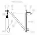
FIG. 17—PULLEY FRAME TOGETHER WITH LOCKED LENGTH ADJUSTING BAR GETS ATTACHED SECURELY TO SCAFFOLDING POLE USING BRACE (PART: 39 NOT PART OF INVENTED PRODUCT)
PART: 1—BACK STRUCTURAL BAR
PART: 2—SUPPORT BAR
PART: 3—TOP WEIGHT HOLDING BAR
PART: 4—BOTTOM PULLEY STABILIZER YOKE
PART: 5—U SHAPE BRACE YOKE
PART: 9—THREADED HAND KNOB
PART: 12—TOP EXTENDING BAR
PART: 13—TRIANGULAR HOOK TO ATTACH PULLEY ROPE BLOCK
PART: 14—LOCK PIN
PART: 39—SCAFFOLDING POLE
FIG. 18—CHOCKER HOOK WITH ROPE FED THROUGH PULLEY ROPE BLOCK GETS
LACHED ONTO TRIANGUAL HOOK
PART: 1—BACK STRUCTURAL BAR
PART: 2—SUPPORT BAR
PART: 3—TOP WEIGHT HOLDING BAR
PART: 4—BOTTOM PULLEY STABILIZER YOKE
PART: 5—U SHAPE BRACE YOKE
PART: 9—THREADED HAND KNOB
PART: 12—TOP EXTENDING BAR
PART: 13—TRIANGULAR HOOK TO ATTACH PULLEY ROPE BLOCK
PART: 14—LOCK PIN
PART: 24—BLOCK HOOK
PART: 33—BODY OF SLIDING CHOKER HOOK
PART: 37—⅝ RAIDED POLY ROPE WITH LOOPED END
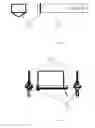
FIG. 19—REPRESENTATION OF INVENTION AS IT WOULD BE UTILIZED AT A CONSTRUCTION SITE
FIG. 20—PERSON ON GROUND LEVEL WOULD ATTACH WEIGHT TO CHOKER HOOK, PULL ON OTHER SIDE OF ROPE, WHILE PULLING WEIGHT UP, ANOTHER PERSON ON TOP OF SCAFFOLDING WOULD RECEIVE AND UNLOAD WEIGHT.
INVENTION DESCRIPTION
The invention is a pump jack pulley. It is used to carry tools and materials to scaffolding table without the use of a ladder, which minimizes the number of trips and eliminates a time waste. The heavy lifting of construction material also decreases the risk of back injuries on the job.
Assembly by Manufacturer
Step 1: Manufacturing of the BRACE, as shown in FIG. 5. One arm of the U-SHAPED YOKE (FIG. 7) needs a slot for insertion of LATCH-6 that would need to be secured. The opposite arm needs a HINGE. LATCH-6 needs to be attached with BOLT-7 that would go through the LATCH SLOT into HINGE and hold LATCH in place. LATCH-6 also needs a slot, the purpose of which is to allow insertion of latch into YOLK SLOT, and tab on opposite side would keep LATCH from moving.
Then, the THREADED HAND KNOB NUT 8 needs to be welded to LATCH 6, as shown in FIG. 6. THREADED HAND KNOB 9 would feed in to HAND KNOB NUT 8.
Step 2: Manufacturing of PULLEY FRAME, FIG. 8. A hole is to be drilled at the top of the BACK STRUCTURAL BAR-1 to attach the brace with THREADED BRACE BOLT-10 and BRACE NUT-11. FIG. 4 shows the BOTTOM PULLEY STABILIZER YOKE-4 that is to be attached to BACK STRUCTURAL BAR-1. FIG. 3 shows how to weld the TOP WEIGHT HOLDING BAR-3 to BACK STRUCTURAL BAR-1. TOP WEIGHT HOLDING BAR-3 needs to have one main hole that eventually will feed LOCK PIN (FIG. 10) through. The SUPPORT BAR-2 in FIG. 2 would serve as support between TOP WEIGHT HOLDING BAR-3 and BACK STRUCTURAL BAR-1.
Step 3: Manufacturing of LENGTH ADJUSTING BAR, FIG. 9. TOP EXTENDING BAR-12 needs five holes to be drilled, same length apart, to allow for length adjustment. TRIANGUAL HOOK-13 needs to be welded onto LENGTH ADJUSTING BAR-12 on the opposite side of drilled holes.
Step 4: Manufacturing of SQUARE WIRE LOCK PIN, FIG. 10. LOCK PIN-14 needs to have a hole at the head that keeps wire in place, but allows for locking and unlocking when necessary.
Step 5: Manufacturing of PULLEY ROPE BLOCK, FIG. 12. All parts of PULLEY ROPE BLOCK need to be manufactured and assembled into one piece. The UPPER BOLT-16 goes through the UPPER HOLE of RIGHT STRUCTURE PLATE-18. Then CILINDER BOLT SPACER-19 needs to be assembled onto the bold after it is fed through PLATE-18 to allow for space between structural plates.
To assemble BLOCK HOOK-24, the LOCK PIN-27 needs to be fed through LATCH-25 and SPRING-26. The BLOCK HOOK-24, once assembled, needs to be placed onto CILINDER BOLT SPACER-19.
Bottom BOLT-17 also needs to feed through bottom hole of RIGHT STRUCTURAL PLATE-18, followed by RIGHT SPACER-20. BLOCK WHEEL BEARING-22 needs to then be pressed into ROPE BLOCK-21. Once the BLOCK and BEARING are married together, they need to go onto BOTTOM BOLT-17, followed by SPACER-23.
The LEFT STRUCTURAL PLATE-28 that is identical to RIGHT STRUCTURAL PLATE-18 needs to be placed onto BOLT-16 and 17. The UPPER WASHER-29 needs to go onto the UPPER BOLT-16, and UPPER LOCK NUT NYLON INSERT-30 would be used to tighten both plates together. Same procedure to be repeated for parts on LOWER BOLT-17, parts include WASHER-31 and tightening of plates by LOWER LOCK NUT NYLON INSERT-32.
Step 6: Manufacturing of 3½—-4 LB SLIDING CHOKER HOOK WITH LATCH in FIG. 14. The CHOKER HOOK LOCK PIN-36 needs to be fed through CHOKER HOOK LATCH-35 and CHOKER HOOK SPRING-34 and placed onto the body of the SLIDING CHOKER HOOK-33.
Step 7: Making a loop with the ⅝ RAIDED POLY ROPE-37 and securing it with CLAMP-38, which will hold the loop of rope together, as per FIG. 15.
How it Operates
The functionality of each part is described above in Section 4, Invention Drawing(s) with numbered components and their functionality.
Set up of Pump Jack Pole Pulley on Project
The final product would be packaged in 6 separate pieces. These include: PULLEY FRAME, FIG. 8, LENGTH ADJUSTING BAR, FIG. 9, SQUARE WIRE LOCK PIN, FIG. 10, PULLEY ROPE BLOCK, FIG. 13, 3½-4 LB SLIDING CHOKER HOOK WITH LATCH, FIGS. 14, and ⅝ RAIDED POLY ROPE WITH LOOP, FIG. 15.
Step 1: Place LENGTH ADJUSTING BAR, FIG. 9, into PULLEY FRAME, FIG. 8, to lock EXTENDING BAR WITH SQUARE WIRE LOCK PIN, FIG. 10. Once length is adjusted, assembly should look as in FIG. 11.
Step 2: Secure product from FIG. 11 to scaffolding pole using BRACE. Product must be secured high enough above the working wall area, as per FIGS. 17, 19, and 20.
Step 3: Feed ⅝ RAIDED POLY ROPE WITH LOOPED END through SLIDING CHOKER HOOK, as per FIG. 15.
Step 4: Product from FIG. 15 gets fed through PULLEY ROPE BLOCK, as per FIG. 16.
Step 5: Product from FIG. 16 gets latched onto HOOK-13. Latching should be after pulley has already been attached to scaffolding pole. See FIG. 18.
FIGS. 19 and 20 show image of final set-up.
Claims
1. This description of my pump jack pulley gives a ‘person having an ordinary skill level in the art (35 USC 103(a))’ the ability to create and use the device in the best way possible. There can be variations, equivalents, and combinations of the device, so one should not take the above description as being the only way or form it can be created. That is, this description is but one representation of what can be done to produce the device to perform in the intended manner. In particular, this invention or its parts may be made of any material, size, shape, color, or weight, as long as the central purpose and function, and basic method of operation are retained, i.e., carry tools and materials to scaffolding table without the use of a ladder.
Images & Drawings included:


Sources:
- United States Patent and Trademark Office - verify current appl. status at the USPTO↗
Recent applications in this class:
- » 20250091843 2025-03-20
Hunting Hoist - » 20240400356 2024-12-05
SHEAVE ASSEMBLY - » 20240400355 2024-12-05
MODULAR PULLEY BLOCK - » 20240217788 2024-07-04
LINE ROLLER ASSEMBLY - » 20230373765 2023-11-23
INSTALLATION DEVICE HAVING POWER-ENGINEERING OR BUILDING-SERVICES MODULES, AND METHOD FOR REMOVING A MODULE FROM AN INSTALLATION DEVICE OF THIS TYPE - » 20230012442 2023-01-12
Rope Grab Device For A Portable Power Driven System - » 20220315399 2022-10-06
Method and extraction system for extracting an electronic device from an immersive cooling container - » 20220274812 2022-09-01
PULLEY - » 20220250884 2022-08-11
Line roller assembly - » 20200354204 2020-11-12
Overhead storage device