Exhaust purification apparatus for internal combustion engine
US20170074144A1
2017-03-16
15/307,618
2015-02-12
✅ Patent granted
US 10,054,027 B2
2018-08-21
WO; PCT/JP2015/053786; 20150212
WO; WO2015/129463; 20150903
Jonathan Matthias
Procopio, Cory, Hargreaves & Savitch LLP
2035-04-14
Abstract:
There is provided an exhaust purification apparatus for an internal combustion engine in which a catalyst capable of adsorbing and oxidizing hydrocarbon is provided in an exhaust pipe, the exhaust purification apparatus including temperature detection means for detecting a temperature of the catalyst, estimation means for accumulating a time during which the temperature of the catalyst detected by the temperature detection means is equal to or less than a predetermined temperature, and estimating an amount of hydrocarbon adsorbed on the catalyst from the accumulated time, and control means for controlling fuel ejection of the internal combustion engine in a first ejection mode in which the temperature of the catalyst is increased to a temperature where hydrocarbons adsorbed on the catalyst are oxidized, in a case in which the amount of hydrocarbons estimated by the estimation means exceeds a predetermined upper limit.
Inventors:
- Tsutomu MURAMOTO 1 🇯🇵 Fujisawa-shi, Kanagawa, Japan
- Nobutaka ISHII 1 🇯🇵 Fujisawa-shi, Kanagawa, Japan
- Futoshi NAKANO 1 🇯🇵 Fujisawa-shi, Kanagawa, Japan
- Takashi YAMASHITA 1 🇯🇵 Fujisawa-shi, Kanagawa, Japan
- Satoshi KANEKIYO 1 🇯🇵 Fujisawa-shi, Kanagawa, Japan
- Kenji HAGIO 1 🇯🇵 Fujisawa-shi, Kanagawa, Japan
- Katsushi OSADA 1 🇯🇵 Fujisawa-shi, Kanagawa, Japan
- Tsugio CHINONE 1 🇯🇵 Fujisawa-shi, Kanagawa, Japan
- Nobutaka Ishii 3 🇯🇵 Fujisawa, Japan
- Futoshi Nakano 12 🇯🇵 Fujisawa, Japan
- Kenji Hagio 6 🇯🇵 Fujisawa, Japan
- Tsutomu Muramoto 1 🇯🇵 Fujisawa, Japan
- Takashi Yamashita 1 🇯🇵 Fujisawa, Japan
- Satoshi Kanekiyo 1 🇯🇵 Fujisawa, Japan
- Katsushi Osada 1 🇯🇵 Fujisawa, Japan
- Tsugio Chinone 1 🇯🇵 Fujisawa, Japan
Assignee:
- Isuzu Motors Limited 626 🇯🇵 Tokyo, Japan
Applicant:
Interested in similar patents?
Get notified when new applications in this technology area are published.
Classification:
F01N9/002 » CPC main
Electrical control of exhaust gas treating apparatus of filter regeneration, e.g. detection of clogging
B01D46/00 IPC
Filters or filtering processes specially modified for separating dispersed particles from gases or vapours
B01D53/9495 » CPC further
Separation of gases or vapours; Recovering vapours of volatile solvents from gases; Chemical or biological purification of waste gases, e.g. engine exhaust gases, smoke, fumes, flue gases, aerosols,; Chemical or biological purification of waste gases of engine exhaust gases by catalytic processes Controlling the catalytic process
F01N3/08 IPC
Exhaust or silencing apparatus having means for purifying, rendering innocuous, or otherwise treating exhaust for rendering innocuous
F01N3/0253 » CPC further
Exhaust or silencing apparatus having means for purifying, rendering innocuous, or otherwise treating exhaust for cooling, or for removing solid constituents of, exhaust by means of filters using means for regenerating the filters, e.g. by burning trapped particles using fuel burner or by adding fuel to exhaust adding fuel to exhaust gases
F01N11/00 IPC
Monitoring or diagnostic devices for exhaust-gas treatment apparatus, e.g. for catalytic activity
F01N3/0814 » CPC further
Exhaust or silencing apparatus having means for purifying, rendering innocuous, or otherwise treating exhaust for rendering innocuous by using absorbents or adsorbents combined with catalytic converters, e.g. NOx absorption/storage reduction catalysts
F01N3/035 » CPC further
Exhaust or silencing apparatus having means for purifying, rendering innocuous, or otherwise treating exhaust for cooling, or for removing solid constituents of, exhaust by means of filters in combination with other devices with catalytic reactors, e.g. catalysed diesel particulate filters
F01N3/0835 » CPC further
Exhaust or silencing apparatus having means for purifying, rendering innocuous, or otherwise treating exhaust for rendering innocuous by using absorbents or adsorbents characterised by the absorbed or adsorbed substances Hydrocarbons
B01D53/94 » CPC further
Separation of gases or vapours; Recovering vapours of volatile solvents from gases; Chemical or biological purification of waste gases, e.g. engine exhaust gases, smoke, fumes, flue gases, aerosols,; Chemical or biological purification of waste gases of engine exhaust gases by catalytic processes
F01N3/025 » CPC further
Exhaust or silencing apparatus having means for purifying, rendering innocuous, or otherwise treating exhaust for cooling, or for removing solid constituents of, exhaust by means of filters using means for regenerating the filters, e.g. by burning trapped particles using fuel burner or by adding fuel to exhaust
F02D41/02 IPC
Electrical control of supply of combustible mixture or its constituents Circuit arrangements for generating control signals
F01N11/002 » CPC further
Monitoring or diagnostic devices for exhaust-gas treatment apparatus, e.g. for catalytic activity the diagnostic devices measuring or estimating temperature or pressure in, or downstream of the exhaust apparatus
F02D41/025 » CPC further
Electrical control of supply of combustible mixture or its constituents; Circuit arrangements for generating control signals; Introducing corrections for particular conditions exterior to the engine in relation with the state of the exhaust gas treating apparatus to increase temperature of the exhaust gas treating apparatus by changing the composition of the exhaust gas, e.g. for exothermic reaction on exhaust gas treating apparatus
F02D41/027 » CPC further
Electrical control of supply of combustible mixture or its constituents; Circuit arrangements for generating control signals; Introducing corrections for particular conditions exterior to the engine in relation with the state of the exhaust gas treating apparatus to purge or regenerate the exhaust gas treating apparatus
F02D41/029 » CPC further
Electrical control of supply of combustible mixture or its constituents; Circuit arrangements for generating control signals; Introducing corrections for particular conditions exterior to the engine in relation with the state of the exhaust gas treating apparatus to purge or regenerate the exhaust gas treating apparatus the exhaust gas treating apparatus being a particulate filter
F02D41/0245 » CPC further
Electrical control of supply of combustible mixture or its constituents; Circuit arrangements for generating control signals; Introducing corrections for particular conditions exterior to the engine in relation with the state of the exhaust gas treating apparatus to increase temperature of the exhaust gas treating apparatus by increasing temperature of the exhaust gas leaving the engine
F02D41/3809 » CPC further
Electrical control of supply of combustible mixture or its constituents; Controlling fuel injection of the high pressure type Common rail control systems
B01D2279/30 » CPC further
Filters adapted for separating dispersed particles from gases or vapours specially modified for specific uses for treatment of exhaust gases from IC Engines
F01N2570/12 » CPC further
Exhaust treating apparatus eliminating, absorbing or adsorbing specific elements or compounds Hydrocarbons
F01N2900/1404 » CPC further
Details of electrical control or of the monitoring of the exhaust gas treating apparatus; Parameters used for exhaust control or diagnosing said parameters being related to the exhaust gas Exhaust gas temperature
F02D2041/389 » CPC further
Electrical control of supply of combustible mixture or its constituents; Controlling fuel injection of the high pressure type for injecting directly into the cylinder
F02D2200/0802 » CPC further
Input parameters for engine control the parameters being related to the engine; Exhaust gas treatment apparatus parameters Temperature of the exhaust gas treatment apparatus
F01N9/00 » CPC further
Electrical control of exhaust gas treating apparatus
F02D41/38 IPC
Electrical control of supply of combustible mixture or its constituents; Controlling fuel injection of the high pressure type
B01D53/944 » CPC further
Separation of gases or vapours; Recovering vapours of volatile solvents from gases; Chemical or biological purification of waste gases, e.g. engine exhaust gases, smoke, fumes, flue gases, aerosols,; Chemical or biological purification of waste gases of engine exhaust gases by catalytic processes Simultaneously removing carbon monoxide, hydrocarbons or carbon making use of oxidation catalysts
F01N3/0871 » CPC further
Exhaust or silencing apparatus having means for purifying, rendering innocuous, or otherwise treating exhaust for rendering innocuous by using absorbents or adsorbents Regulation of absorbents or adsorbents, e.g. purging
F01N3/103 » CPC further
Exhaust or silencing apparatus having means for purifying, rendering innocuous, or otherwise treating exhaust for rendering innocuous by thermal or catalytic conversion of noxious components of exhaust Oxidation catalysts for HC and CO only
B01D53/9477 » CPC further
Separation of gases or vapours; Recovering vapours of volatile solvents from gases; Chemical or biological purification of waste gases, e.g. engine exhaust gases, smoke, fumes, flue gases, aerosols,; Chemical or biological purification of waste gases of engine exhaust gases by catalytic processes; Removing one or more of nitrogen oxides, carbon monoxide, or hydrocarbons by multiple successive catalytic functions; systems with more than one different function, e.g. zone coated catalysts with catalysts positioned on separate bricks, e.g. exhaust systems
B01D2255/912 » CPC further
Catalysts; Physical characteristics of catalysts HC-storage component incorporated in the catalyst
B01D2257/702 » CPC further
Components to be removed; Organic compounds not provided for in groups - Hydrocarbons
B01D2258/012 » CPC further
Sources of waste gases; Engine exhaust gases Diesel engines and lean burn gasoline engines
F01N2250/06 » CPC further
Combinations of different methods of purification afterburning and filtering
F01N2560/06 » CPC further
Exhaust systems with means for detecting or measuring exhaust gas components or characteristics the means being a temperature sensor
F01N2610/03 » CPC further
Adding substances to exhaust gases the substance being hydrocarbons, e.g. engine fuel
F01N2900/1602 » CPC further
Details of electrical control or of the monitoring of the exhaust gas treating apparatus; Parameters used for exhaust control or diagnosing said parameters being related to the exhaust apparatus, e.g. particulate filter or catalyst Temperature of exhaust gas apparatus
F01N3/10 IPC
Exhaust or silencing apparatus having means for purifying, rendering innocuous, or otherwise treating exhaust for rendering innocuous by thermal or catalytic conversion of noxious components of exhaust
F01N13/00 IPC
Exhaust or silencing apparatus characterised by constructional features ; Exhaust or silencing apparatus, or parts thereof, having pertinent characteristics not provided for in, or of interest apart from, groups - , ,
F01N2430/08 » CPC further
Influencing exhaust purification, e.g. starting of catalytic reaction, filter regeneration, or the like, by controlling engine operating characteristics by modifying ignition or injection timing
F01N13/0097 » CPC further
Exhaust or silencing apparatus characterised by constructional features ; Exhaust or silencing apparatus, or parts thereof, having pertinent characteristics not provided for in, or of interest apart from, groups - , , having two or more separate purifying devices arranged in series the purifying devices are arranged in a single housing
F01N2430/085 » CPC further
Influencing exhaust purification, e.g. starting of catalytic reaction, filter regeneration, or the like, by controlling engine operating characteristics by modifying ignition or injection timing at least a part of the injection taking place during expansion or exhaust stroke
Description
TECHNICAL FIELD
The present invention relates to an exhaust purification apparatus for an internal combustion engine.
BACKGROUND ART
In an internal combustion engine such as a diesel engine, nitrogen oxides, particulate matter (PM), and the like are generated because of combustion. In a vehicle in which an internal combustion engine is used for power, in order to suppress discharging of these materials with exhaust gas, an oxidation catalyst (DOC) and a purifying apparatus such as a diesel particulate filter (DPF) are provided in an exhaust passage.
The DPF is an apparatus for collecting PM contained in exhaust gas by using a filter. While the DPF is used, PM is accumulated, and thus functions thereof deteriorate due to clogging of the filter. Therefore, the accumulated PM is combusted by feeding high temperature exhaust gas to the DPF. As a method for generating high temperature exhaust gas, a method of using heat which is generated by allowing unburnt hydrocarbons (HC) to be included in the exhaust gas, adsorbing the HC on a DOC provided on an upstream side, and oxidizing (combusting) the HC is generally used.
However, when the DOC exceeds a usable temperature, the DOC is likely to be degraded, and functions thereof deteriorate. Therefore, when HC is adsorbed and accumulated in the DOC more than necessary, the DOC exceeds the usable temperature at the time of combustion, and thus there is a possibility that the DOC is degraded.
Here, in the exhaust purification apparatus of Patent Literature 1, a passage for guiding exhaust gas to an adsorbent and a passage which does not pass through the adsorbent are provided, and when an estimated value of an amount of accumulated HC in the adsorbent reaches a predetermined value or more, high temperature exhaust gas is guided to the adsorbent by opening the former passage so that the accumulated HC is combusted.
In addition, in a HC adsorbing catalyst of Patent Literature 2, if the amount of accumulated HC which is estimated reaches a predetermined amount, an after-ejection (ejection in expansion cycle) is performed using an injector, a temperature of the exhaust gas is increased, and HC is burnt. In order to estimate the amount of the accumulated HC, there is a method of calculating the amount based on a change of HC concentration between ahead of and behind the HC adsorbing catalyst (former), or a method of estimating an amount of flow of HC to the HC adsorbing catalyst from a measured value of an air fuel ratio sensor and calculating the amount using the estimated amount of flow of HC, an adsorption efficiency of the HC adsorbing catalyst, and an amount of HC-oxidation/desorption of the HC adsorbing catalyst (latter).
CITATION LIST
Patent Literature
[Patent Literature 1] JP-A-H11-22449
[Patent Literature 2] JP-A-2010-265873
SUMMARY OF INVENTION
Technical Problem
However, in an exhaust purification apparatus of Patent Literature 1, two exhaust passages need to be provided, and thus an increase in the number of components or complexity of a structure thereof is caused.
In addition, in Patent Literature 2, at the time of estimating the amount of accumulated HC, a HC concentration sensor needs to be provided ahead of and behind the HC adsorbing catalyst in the former method, and thus an increase in the number of components or complexity of a structure thereof occurs. Meanwhile, the latter method does not take into account the fact that the adsorption efficiency of the HC adsorbing catalyst and the amount of HC-oxidation/desorption of the HC adsorbing catalyst also change due to the amount of HC being accumulated in the HC adsorption catalyst. Therefore, there is a possibility that a fuel efficiency may deteriorate due to excess frequency of burning of HC, and conversely, the temperature may increase to equal to or more than a usable temperature because an amount of accumulated HC at the time of incineration exceeds an appropriate amount.
Here, an object of the invention is to provide an exhaust purification apparatus for an internal combustion engine which combusts hydrocarbons adsorbed to a catalyst at an appropriate timing while avoiding an increase in the number of components and the complexity of a structure.
Solution to Problem
In order to solve the above-described object, the invention provides an exhaust purification apparatus for an internal combustion engine in which a catalyst capable of adsorbing and oxidizing hydrocarbons is provided in an exhaust pipe, the exhaust purification apparatus including: temperature detection means for detecting a temperature of the catalyst; estimation means for accumulating a time during which the temperature of the catalyst detected by the temperature detection means is equal to or less than a predetermined temperature, and estimating an amount of hydrocarbons adsorbed on the catalyst from the accumulated time; and control means for controlling fuel ejection of the internal combustion engine in a first ejection mode in which the temperature of the catalyst is increased to a temperature where hydrocarbons adsorbed on the catalyst are oxidized, in a case in which the amount of hydrocarbons estimated by the estimation means exceeds a predetermined upper limit.
Subtraction may be performed to the accumulated time when the temperature of the catalyst detected by the temperature detection means exceeds the predetermined temperature continuously for a predetermined time.
The exhaust purification apparatus may further include a filter that is provided in the exhaust pipe downstream from the catalyst and collects particulate matter in exhaust gas, and when the particulate matter accumulated in the filter exceeds a predetermined amount, the control means may control the fuel ejection of the internal combustion engine in a second ejection mode in which the temperature of the catalyst is increased to a combustion temperature of the particulate matter.
The control means may prohibit performing the second ejection mode while the first ejection mode is performed.
BRIEF DESCRIPTION OF DRAWINGS
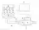
FIG. 1 is a view illustrating an internal combustion engine and an exhaust purification apparatus according to an embodiment of the invention.
FIG. 2-1 is a diagram describing a fuel ejecting control in a general mode.
FIG. 2-2 is a diagram describing the fuel ejecting control in a HC purge mode.
FIG. 2-3 is a diagram describing the fuel ejecting control in a temperature raising process of a DPF regeneration mode.
FIG. 2-4 is a diagram describing the fuel ejecting control in a HC supplying process of the DPF regeneration mode.
FIG. 3 is a diagram illustrating a temperature change (solid line) of a DOC in HC pu rge, and a change (dashed line) of an amount of the HC being adsorbed.
FIG. 4 is a diagram illustrating an example of a change of an exhaust gas temperature according to driving of an engine.
FIG. 5 is a diagram illustrating a change of an amount of adsorbed HC in the DOC in a case in which the HC purge is performed (solid line), and a case in which the HC purge is not performed (dashed line).
FIG. 6 is a diagram illustrating a temperature change of the DOC in a DPF regeneration.
FIG. 7 is a view illustrating an internal combustion engine and an exhaust purification apparatus according to another embodiment of the invention.
DESCRIPTION OF EMBODIMENTS
Hereinafter, an exhaust purification apparatus according to an embodiment of the invention will be described on the basis of attached drawings. A same number is given to a same component, and a name and a function thereof are also same. Therefore, detailed description thereof will not be repeated.
<Configuration of Internal Combustion Engine and Exhaust Purification Apparatus>
FIG. 1 is a view illustrating a configuration of an internal combustion engine and an exhaust purification apparatus according to an embodiment of the invention. In the embodiment, as the internal combustion engine, a diesel engine 10 (hereinafter, simply referred to as engine) is used.
In each cylinder of an engine 10, an injector 21 which directly ejects a high pressure fuel accumulated in a common rail 20 into each cylinder is provided. An ejection amount of fuel and an ejection timing of fuel of the injector 21 are controlled according to an ejection instruction signal which is input from an electronic control unit (hereinafter, referred to as ECU) 40. In the embodiment, material ejection of the injector 21 can be switched from a general mode, a HC purge mode, and a DPF regeneration mode. Each mode will be described later in detail.
An exhaust gas passage 12 discharging the exhaust gas to the air is connected to an exhaust manifold 11 of the engine 10. In the exhaust gas passage 12, an exhaust gas temperature sensor 13, a post-exhaust processing device 14, and the like are provided sequentially from an upstream side of exhausting.
The exhaust gas temperature sensor 13 detects an exhaust gas temperature (hereinafter, refer to detection temperature) θ at an upstream side than the post-exhaust processing device 14. The detection temperature θ detected by the exhaust gas temperature sensor 13 is transmitted in real time to an ECU 40 which is electrically connected.
The post-exhaust processing device 14 is configured with a DOC 15 and a DPF 16 which are disposed inside a catalyst case 14a sequentially from the upstream side of exhausting. Also, a numeral 17 indicates a differential pressure sensor which detects the a head-and-behind differential pressure ΔP of the DPF. The ahead-and-behind differential pressure ΔP detected by the differential pressure sensor 17 is transmitted in real time to the ECU 40 electrically connected.
The DOC 15 is formed by carrying a catalyst component on a surface of a ceramic carrier such as a cordierite honeycomb structure, or the like. In addition, an adsorbent for adsorbing HC contained in the exhaust gas is included in the DOC 15. The adsorbent is formed of a material having a three dimensional structure for capturing HC molecules such as zeolite. The adsorbed HC is oxidized (combusted), and thus the exhaust gas temperature can be increased. However, when unburnt HC generated in the DPF regeneration and a general driving to be described later is accumulated in the DOC 15, HC of an excess amount is combusted, and thus there is a possibility that the exhaust gas temperature exceeds a use upper limit temperature θL. Therefore, the HC purge is performed in order to combust and remove the accumulated HC. The details of the HC purge will be described later.
The DPF 16 is formed by disposing a plurality of cells divided using porous partition walls along a flowing direction of exhausting and alternately sealing an upstream side and a downstream side of the cells. The DPF 16 collects a particulate matter (hereinafter, refer to PM) in the exhaust gas on pores or a surface (filter) of partition walls. When an accumulate amount of PM reaches a predetermined amount, so called the DPF regeneration which removes the predetermined amount by firing is performed. Detailed description of the DPF regeneration will be described later.
<Fuel Ejecting Control>
(1) General Mode
FIG. 2-1 is a diagram describing a fuel ejecting control in a general mode. In the general mode, fuel ejection (main ejection) is performed at a top dead point or a vicinity thereof. Also, in the general mode described here, the main ejection is performed once, but it is only an example, and ejection may be performed separately several times (multiple ejection) in accordance with a necessary performance.
(2) HC Purge Mode
FIG. 2-2 is a diagram describing a fuel ejecting control in a HC purge mode. In the HC purge mode, in addition to the main ejection, an ejection by an ejection amount less than an amount of fuel ejected in the main ejection is respectively performed once before and after the main ejection (pre-ejection and after-ejection). In the HC purge mode, the exhaust gas temperature becomes higher than that of the general mode, and a temperature of the DOC 15 is increased up to a target temperature θB higher than a temperature (active temperature θA) where HC can be combusted. Also, a control of the HC purge mode described herein is only an example, and the other type of control may be used as long as a temperature of the DOC 15 is increased up to the target temperature θB.
(3) DPF Regeneration Mode
In the DPF regeneration mode, at first, ejection for increasing the temperature of the DOC 15 is performed (temperature raising process of FIG. 2-3), and after that, it is switched to ejection for supplying HC to the DOC 15 (HC supplying process of FIG. 2-4).
FIG. 2-3 is diagram describing a fuel ejecting control in a temperature raising process of the DPF regeneration mode. In the temperature raising process, the pre-ejection, the main ejection, and the after-ejection are performed. The ejection amount of the after-ejection in the temperature raising process is much more than that of the after-ejection in the HC purge mode. The temperature of the DOC 15 is increased by the ejection in the temperature raising process, and it is switched to the HC supplying process if the temperature reaches a predetermined temperature higher than the target temperature 9B.
FIG. 2-4 is a diagram describing the fuel ejecting control in the HC supplying process of the DPF regeneration mode. In the HC supplying process, in addition to fuel ejection of the temperature raising process, fuel ejection is further performed (post-ejection) at an exhaust cycle after combustion. In this ejection mode, fuel by the post-ejection is not combusted, and is included in the exhaust gas. Therefore, HC contained in the fuel is supplied to the DOC 15. Since the temperature of the DOC 15 has been sufficiently increased, the supplied HC is combusted by the DOC 15. Here, the control of the post-ejection is not limited thereto, may be a control to perform ejection in multiple times as long as the ejection is performed after combustion and an unburnt fuel is supplied to the DOC 15 by exhaust.
<HC Purge>
FIG. 3 is a diagram illustrating a temperature change (solid line) of the DOC 15 and a change (dashed line) of an adsorption amount of HC in the HC purge. In the drawing, the use upper limit temperature θL indicates a temperature in order not to cause a significant degrading of the DOC 15.
When the HC purge starts, fuel ejection of the HC purge mode is performed, and the temperature of the DOC 15 is also increased according to an increase of the exhaust gas temperature. If the temperature of the DOC 15 reaches the active temperature θA, the HC adsorbed to the DOC 15 starts to be combusted. Accordingly, the temperature of the DOC 15 is further increased, but since the amount of adsorbed HC is suppressed to be lower than a predetermined amount by a control to be described later, the temperature does not reach to the use upper limit temperature θL.
When the amount of HC adsorbed to the DOC 15 is reduced by the combustion of HC and the HC is sufficiently removed, the HC purge is finished. Time from starting to finishing of the HC purge is appropriately adjusted according to conditions such as an amount of HC to be removed, a size of the DOC 15, and an amount of flowing of the exhaust gas.
<Execution Condition of HC Purge>
FIG. 4 is a diagram illustrating an example of a change of the exhaust gas temperature according to driving of the engine 10. In the embodiment, the amount of adsorbed HC of the DOC 15 is estimated based on a relationship of temperature θ and time T detected by the exhaust gas temperature sensor 13, and it is determined whether to perform the HC purge or not. This estimation and determination are performed by the ECU 40.
In the embodiment, a time during which the detection temperature θ is equal to or less than the active temperature θA is integrated, and when the integrated time ΣT (=TA1+TA2+TA3+TA4+ . . . ) becomes a predetermined value TA, it is estimated that the amount of adsorbed HC in the DOC 15 has reached an amount to be HC-purged, and the start of the HC purge is determined. The θA and TA can be, for example, calculated experimentally, and further, these can be appropriately adjusted by, for example, expecting drop of temperature between the exhaust gas temperature sensor 13 and the DOC 15. In addition, the amount to be HC-purged is an amount of which the temperature of the DOC 15 does not reach the use upper limit temperature θL at the time of combustion of HC in the DOC 15.
If it does not become equal to or more than the active temperature OA, the combustion of HC does not occur. Therefore, an estimation method of the amount of adsorbed HC of the embodiment, in which it is determined that HC is accumulated when the temperature of the DOC 15 is less than the active temperature θA, is an accurate and stable method.
Further, in addition to these conditions, in the embodiment, when the exhaust gas temperature becomes a predetermined temperature, for example, a state in which the temperature is equal to or more than the target temperature θB (>θA) is continuously maintained for equal to or more than a predetermined time TB, a value of ΣT is reset (ΣT=0). The reason is because, if the exhaust gas temperature is sufficiently high, it can be estimated that the HC adsorbed to the DOC 15 is sufficiently combusted. Here, in order to set the temperature inside the DOC 15 to be θB, by expecting drop of the temperature between the exhaust gas temperature sensor 13 and the DOC 15, temperature used for determination may be set to, for example, θB+Δ. In addition, when ΣT=(TA1+TA2+TA3+TA4+ . . . )−kTB (k is a coefficient determined by combustion efficiency of HC, and for example, can be calculated by experiment) reaches a predetermined value, the HC purge may set to be started (ΣT≧0).
FIG. 5 is a diagram illustrating a change of the amount of adsorbed HC in the DOC 15 in a case in which the HC purge is performed (solid line), and a case in which the HC purge is not performed (dashed line). According to driving of the engine 10, a small amount of unburnt HC included in the exhaust gas is accumulated, and an adsorption amount of HC is increased. Then, when it is determined that the amount of adsorbed HC has reached a predetermined amount as described above, and the HC purge is performed, HC is removed. Therefore, according to the embodiment, the amount of adsorbed HC in the DOC 15 is controlled not to exceed a predetermined amount. In addition, therefore, the adsorption amount of HC does not become great as shown by the dashed line and thus does not exceed the use upper limit temperature θL at the time of the DPF regeneration to be described later. In addition, since the HC purge is not performed more than necessary, consumption of unnecessary fuel is suppressed.
The estimation of the amount of adsorbed HC as described above, that is, a control method for determining whether or not the HC purge is to be performed is simply an example, and for example, the determination may be made on the basis of an integrated value of a distance as much as a vehicle has traveled in a state in which the exhaust gas temperature is equal to or lower than the θA.
<DPF Regeneration>
FIG. 6 is a diagram illustrating the temperature change of the DOC 15 in the DPF regeneration. In the drawing, a solid line indicates temperature changes in a case in which the HC purge of the embodiment is performed, and a dashed line indicates the temperature change in a case in which the HC purge is not performed. The DPF regeneration is performed by combusting unburnt fuel (HC) in the exhaust gas using the DOC 15 so as to increase the temperature of the DOC 15 and increase the exhaust gas temperature flowing into the DPF 16 up to a PM combustion temperature.
When the PM accumulated in the DPF 16 is increased, the ahead-and-behind differential pressure ΔP of the DPF 16 is increased. Therefore, in the embodiment, a starting condition of the DPF regeneration is when the ahead-and-behind differential pressure ΔP detected by the differential pressure sensor 17 is equal to or more than a predetermined value. However, in the embodiment, the ahead-and-behind differential pressure ΔP is not detected during performing the HC purge, and the DPF regeneration is not started. It is because that a detection accuracy of the differential pressure sensor 17 during performing the HC purge is deteriorated. In addition, it is also because that there is a possibility that the temperature of HC reaches the use upper limit temperature θL when HC is further supplied and combusted in a state in which the HC is accumulated.
Here, the embodiment (solid line) will be described. When the DPF regeneration is started, fuel ejection of the DPF regeneration mode is started. First, the DOC 15 is increased by the fuel ejection in the temperature raising process. After that, when it is switched to the HC supplying process and HC is supplied to the DOC 15 and combusted, the temperature of the DOC 15 is further increased, and reaches θPM. A high temperature exhaust gas passed through the DOC 15 flows into the DPF 16 at a temperature equal to or more than the PM combustion temperature.
Meanwhile, in a case in which excess HC is accumulated in the DOC 15 without performing the HC purge of the embodiment, when the DOC 15 is increased as shown by the dashed line, the temperature is rapidly increased, and the temperature of the DOC 15 reaches the use upper limit temperature θL. When the temperature of the DOC 15 reaches the use upper limit temperature θL, a three dimensional structure of an adsorbent included in the DOC 15 collapses, and an adsorption performance of HC is deteriorated.
Effect of Embodiment
The HC purge of the embodiment can be performed by rewriting a program of the ECU 40, and the engine 10 and the injector 21 do not need to be modified in design, or the like for this control. Further, determination of the whether to perform the HC purge is performed on the basis of the detection temperature θ by the exhaust gas temperature sensor 13, and the exhaust gas temperature sensor 13 is a component also used for a controlling a driving state of the engine 10, a temperature at the time of the DPF regeneration, and the like.
In addition, as described above, a method of determining whether or not HC is accumulated using the temperature of the DOC 15 (detection temperature θ of exhaust gas temperature sensor 13), and estimating the amount of adsorbed HC in the embodiment is an accurate and stable method. Therefore, when the HC purge is determined to be performed or not based on this estimation, the HC purge can be performed at an accurate timing.
Therefore, according to the embodiment, the exhaust purification apparatus for the internal combustion engine which combusts hydrocarbon adsorbed to the DOC 15 at an appropriate timing while avoiding an increase in the number of components and the complexity of a structure can be provided.
Other Embodiment
FIG. 7 is a view illustrating the internal combustion engine and the exhaust purification apparatus according to another embodiment of the invention. This embodiment is different from the embodiment described above in a configuration in that a fuel ejection nozzle 18 is provided between the engine 10 and the post-exhaust processing device 14.
In this configuration, since fuel (HC) can be supplied from the fuel ejection nozzle 18, as a fuel ejection method using the injector 21 in the DPF regeneration mode, only the process (temperature raising process) of FIG. 2-3 is necessary. In this configuration, since the HC is supplied at the outside of the engine, an exhaust process after combustion like the post-ejection (FIG. 2-4) is not necessary, and thus ejection timing can be set more freely.
Claims
1. An exhaust purification apparatus for an internal combustion engine in which a catalyst capable of adsorbing and oxidizing hydrocarbons is provided in an exhaust pipe, the exhaust purification apparatus comprising:
temperature detection means for detecting a temperature of the catalyst;
estimation means for accumulating a time during which the temperature of the catalyst detected by the temperature detection means is equal to or less than a first predetermined temperature, and estimating an amount of hydrocarbons adsorbed on the catalyst from the accumulated time; and
control means for controlling fuel ejection of the internal combustion engine in a first ejection mode in which the temperature of the catalyst is increased to a temperature where hydrocarbons adsorbed on the catalyst are oxidized, in a case in which the amount of hydrocarbons estimated by the estimation means exceeds a predetermined upper limit.
2. The exhaust purification apparatus according to claim 1,
wherein subtraction is performed to the accumulated time when the temperature of the catalyst detected by the temperature detection means becomes a temperature equal to or more than a second predetermined temperature higher than the first predetermined temperature continuously for a predetermined time.
3. The exhaust purification apparatus according to claim 1, further comprising:
a filter that is provided in the exhaust pipe downstream from the catalyst and collects particulate matter in exhaust gas,
wherein, when the particulate matter accumulated in the filter exceeds a predetermined amount, the control means controls the fuel ejection of the internal combustion engine in a second ejection mode in which the temperature of the catalyst is increased to a combustion temperature of the particulate matter.
4. The exhaust purification apparatus according to claim 3,
wherein the control means prohibits performing the second ejection mode while the first ejection mode is performed.
5. An exhaust purification apparatus for an internal combustion engine, the exhaust purification apparatus comprising:
a catalyst capable of adsorbing and oxidizing hydrocarbons and provided in an exhaust pipe;
a temperature sensor configured to detect a temperature of the catalyst; and
a controller configured to:
accumulate a time during which the temperature of the catalyst detected by the temperature sensor is equal to or less than a first predetermined temperature, and estimate an amount of hydrocarbons adsorbed on the catalyst from the accumulated time; and
control fuel ejection of the internal combustion engine in a first ejection mode in which the temperature of the catalyst is increased to a temperature where hydrocarbons adsorbed on the catalyst are oxidized, in a case in which the estimated amount of hydrocarbons exceeds a predetermined upper limit.
6. The exhaust purification apparatus according to claim 5,
wherein the controller is further configured to:
reduce the accumulated time when the temperature of the catalyst detected by the temperature sensor becomes a temperature equal to or more than a second predetermined temperature higher than the first predetermined temperature continuously for a predetermined time.
7. The exhaust purification apparatus according to claim 5, further comprising:
a filter that is provided in the exhaust pipe downstream from the catalyst and collects particulate matter in exhaust gas,
wherein, when the particulate matter accumulated in the filter exceeds a predetermined amount, the controller controls the fuel ejection of the internal combustion engine in a second ejection mode in which the temperature of the catalyst is increased to a combustion temperature of the particulate matter.
8. The exhaust purification apparatus according to claim 7,
wherein the controller prohibits performing the second ejection mode while the first ejection mode is performed.
Images & Drawings included:


Sources:
- United States Patent and Trademark Office - verify current appl. status at the USPTO↗
Similar patent applications:
- » 20100229530
Control device and control method for exhaust gas purification apparatus, and internal combustion engine exhaust gas purification apparatus - » 20100319316
Oxidation catalyst fault diagnosis unit and oxidation catalyst fault diagnosis method and internal combustion engine exhaust purification apparatus - » 20100319651
Temperature sensor plausibility diagnosis unit and plausibility diagnosis method and internal combustion engine exhaust purification apparatus - » 20140165539
Reducing agent supply apparatus and internal-combustion engine exhaust gas purification apparatus - » 10419884
Internal combustion engine exhaust gas purification apparatus, exhaust gas purification process and exhaust gas purification catalyst - » 10768141
Exhaust purification apparatus for internal combustion engine - » 20070051098
Regeneration controller for exhaust purification apparatus of internal combustion engine - » 20060137328
Exhaust purification method and exhaust purification apparatus of internal combustion engine - » 20060213188
Regeneration controller for exhaust purification apparatus of internal combustion engine - » 20070137180
Regeneration controller for exhaust purification apparatus of internal combustion engine
Recent applications in this class:
- » 20250283424 2025-09-11
CONTROL DEVICE FOR INTERNAL COMBUSTION ENGINE - » 20250215818 2025-07-03
MODEL PREDICTIVE CONTROL FOR AFTERTREATMENT REGENERATION - » 20240159179 2024-05-16
Exhaust Gas Aftertreatment System and Method - » 20240003283 2024-01-04
Work Machine - » 20230323803 2023-10-12
DPF regeneration trigger control method and terminal device, and storage medium - » 20230272731 2023-08-31
Systems and methods of using diesel particulate filter heater as a load bank - » 20230243287 2023-08-03
Work vehicle including DPF - » 20230184153 2023-06-15
Systems and methods for maintaining aftertreatment capability during vehicle life - » 20230135221 2023-05-04
Method and device for diagnosing a coated particulate filter arranged in an exhaust-gas duct of a motor vehicle - » 20230042626 2023-02-09
CONTROL APPARATUS FOR INTERNAL COMBUSTION ENGINE
Recent applications for this Assignee:
- » 20250050696 2025-02-13
VEHICLE - » 20240424849 2024-12-26
VEHICLE - » 20240401542 2024-12-05
Control device - » 20240211707 2024-06-27
Reading controller and reading control method - » 20240198903 2024-06-20
Safe driving determination apparatus - » 20240178725 2024-05-30
Trilateral cycle system - » 20240176968 2024-05-30
Reading control device, reading control method, and vehicle - » 20240141813 2024-05-02
Exhaust gas aftertreatment device for internal combustion engine - » 20240133466 2024-04-25
Electric parking brake device for vehicle - » 20240101143 2024-03-28
ELECTRONIC DEVICE, VEHICLE, DISPLAY CONTROL METHOD, AND STORAGE MEDIUM