Integral cap sample cup
US20170080415A1
2017-03-23
14/862,546
2015-09-23
✅ Patent granted
US 10,179,333 B2
2019-01-15
-
-
Jill A Warden | Jacqueline Brazin
Joseph Beckman
2035-09-23
Abstract:
This invention relates to the design and construction of a novel sample cup including an integral cap for use in XRF Spectroscopy.
Assignee:
- Premier Lab Supply Inc. 5 🇺🇸 Port St. Lucie, FL, United States
Applicant:
Interested in similar patents?
Get notified when new applications in this technology area are published.
Classification:
B01L3/502 » CPC main
Containers or dishes for laboratory use, e.g. laboratory glassware ; Droppers; Containers for the purpose of retaining a material to be analysed, e.g. test tubes with fluid transport, e.g. in multi-compartment structures
B01L2300/042 » CPC further
Additional constructional details; Closures and closing means; Connecting closures to device or container Caps; Plugs
B01L2300/043 » CPC further
Additional constructional details; Closures and closing means; Connecting closures to device or container Hinged closures
B01L2300/0848 » CPC further
Additional constructional details; Geometry, shape and general structure Specific forms of parts of containers
B01L2300/0861 » CPC further
Additional constructional details; Geometry, shape and general structure Configuration of multiple channels and/or chambers in a single devices
G01N2021/7786 » CPC further
Investigating or analysing materials by the use of optical means, i.e. using sub-millimetre waves, infrared, visible or ultraviolet light; Systems in which material is subjected to a chemical reaction, the progress or the result of the reaction being investigated by observing the effect on a chemical indicator; Measurement method of reaction-produced change in sensor Fluorescence
B01L2200/141 » CPC further
Solutions for specific problems relating to chemical or physical laboratory apparatus; Process control and prevention of errors Preventing contamination, tampering
B01L3/00 IPC
Containers or dishes for laboratory use, e.g. laboratory glassware ; Droppers
G01N21/77 » CPC further
Investigating or analysing materials by the use of optical means, i.e. using sub-millimetre waves, infrared, visible or ultraviolet light; Systems in which material is subjected to a chemical reaction, the progress or the result of the reaction being investigated by observing the effect on a chemical indicator
B01L2200/0621 » CPC further
Solutions for specific problems relating to chemical or physical laboratory apparatus; Fluid handling related problems Control of the sequence of chambers filled or emptied
B01L2300/044 » CPC further
Additional constructional details; Closures and closing means; Connecting closures to device or container pierceable, e.g. films, membranes
B01L2300/047 » CPC further
Additional constructional details; Closures and closing means; Function or devices integrated in the closure Additional chamber, reservoir
B01L2300/048 » CPC further
Additional constructional details; Closures and closing means; Function or devices integrated in the closure enabling gas exchange, e.g. vents
G01N2223/307 » CPC further
Investigating materials by wave or particle radiation; Accessories, mechanical or electrical features cuvettes-sample holders
G01N23/223 » CPC further
Investigating or analysing materials by the use of wave or particle radiation, e.g. X-rays or neutrons, not covered by groups – , or by measuring secondary emission from the material by irradiating the sample with X-rays or gamma-rays and by measuring X-ray fluorescence
B01L2300/0832 » CPC further
Additional constructional details; Geometry, shape and general structure cylindrical, tube shaped
Description
FIELD OF THE INVENTION
This invention relates to the design and construction of a novel sample cup including an integral cap for use in XRF Spectroscopy.
BACKGROUND OF THE INVENTION
The present invention describes a novel sample cup including an integral cap for use in XRF Spectroscopy.
Spectroscopic analysis (XRF Spectroscopy) utilizes sample cups to contain liquid or powder samples for elemental analysis. Sample cups generally have a thin transparent film bottom and may include a top end formed integral with the cup body known as a single ended design. Alternatively, the sample cup may include a second thin film or be secured at the top end, known as a double open end design. Sample cups are generally delivered to the analyst in parts comprised of a side wall member and complementary secondary member, which members are assembled in combination with a separate thin film component to construct a single sample cup. The sample cup, with its liquid or powder sample contained therein, is then manually transported to an XRF instrument and placed in a holder, thin film bottom down, for analysis.
Sample cups are configured in various sizes to accommodate different analytical instruments and testing purposes. Some sample cups are dimensioned very small and are particularly difficult to handle. A sample cup design utilizing a separate cap assembly to be manually applied to the sample cup body after deposit of the sample into the sample cup body requires manipulating the sample cup body, sample deposit and cap assembly. This creates handling problems and opportunities for contamination of the sample and contamination or damage to the thin film assembled to the bottom of the sample cup. The ability to reduce the number of manipulated items, particularly when sized very small, increases technician productivity and reduces the opportunities for contamination or damage to the sample cup and sample specimen.
The present invention avoids these disadvantages, being easily manipulated with one hand while dispensing a liquid sample and then being securely sealed for safe and contaminant-free handling.
BRIEF DESCRIPTION OF THE DRAWINGS
FIGS. 1-9 are various views (elevation and perspective) of two embodiments of the integral cap sample cup.
DETAILED DESCRIPTION OF THE INVENTION
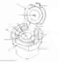
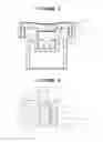
Shown in FIG. 1 is an integral cap sample cup comprising a sample cup lower body (1) with a bottom open end, a flanged cup upper body (2) with a top open end, integral cap (3) secured to upper body (2) via a hinge (4). The cap (3) includes a vent hole (5) for pressure equalization and gas release, particularly when volatile liquid samples exist, and also includes a pull tab (6) for manipulation of the cap (3) and securing said cap in a closed position on upper body (2). Upper body (2) includes overflow chambers (7) for the collection of escaping liquids or collection of liquefied escaping gases during testing. Channels to funnel any escaping liquids or gases to said overflow chambers are provided as indicated. A first channel (19) extends from the top outside edge of an inner chamber (8) to an overflow chamber (7). A second channel (20) is situated circumferentially about the upper body top open end. The second channel may completely or partially encircle the upper body top open end. Suspended from upper body (2) is inner chamber (8). Inner chamber (8) includes one or more cutouts (10) to allow pipette deposited liquid to settle within the lower body (1) interior and be contained by a thin film secured by an outer member (not shown in FIG. 1). Said inner chamber is dimensioned to allow for insertion of a pipette and contains a bottom stop (not shown in FIG. 1) to prevent said pipette from contacting and damaging the thin film. The upper body may be dimensioned to include parallel opposing flat surfaces (2A and 2B) disposed perpendicular to said top open end of said upper body (2).
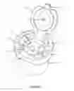
Shown in FIG. 2 is a partial top perspective view of the integral cap sample cup with the integral cap in the closed position. Said cap may be secured in the closed position via frictional fit with upper body (2) or via a hook and slot configuration.
Shown in FIG. 3 is a partial bottom perspective view of the integral cap sample cup with the integral cap in the closed position. In this view, the bottom stop (9) of the inner chamber (8) is shown with a cutout (10) for deposit of the liquid into the lower body interior. The outer member (11) is shown in place over lower body (1). In assembly, a thin film is placed over the bottom open end of lower body (1) and said outer member (11) then secures said thin film by friction placement as shown.
Shown in FIG. 4 is a bottom elevation view of the integral cap sample cup. The lower body (1), outer member (11) and upper body (2) are shown along with the bottom stop (9) of inner chamber (8) and bottom cutout (10).
Shown in FIG. 5 is a top elevation view of the integral cap sample cup. The upper body (2) is shown along with the cap (3) in a closed position, hinge (4) and pull tab (6). Four overflow chambers (7) are evident along with vent hole (5).
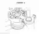
Shown in FIG. 6 is the integral cap sample cup with an alternative cap. The cap utilizes two opposing locking tabs (12). Upon closing said cap, each locking tab inserts in a corresponding slot (13) located on the upper surface of the upper body. Said locking tabs may secure the cap via a frictional fit with their corresponding slots. Alternatively, each locking tab may utilize a hooked portion (14) which mates with a corresponding hooked portion (15) positioned within each of said corresponding slots. In lieu of hooked portions, the locking tab and corresponding slot may utilize a groove and detent method to secure the cap in a closed position. First channel (19) and second channel (20) are shown in relation to inner chamber (8) and upper body (2) top open end. Also shown in FIG. 6 is outer member (11) configured to include a gripping means (11A) situated on a lower portion of said outer member to facilitate handling of the assembled sample cup. The gripping means may be ridges, stippling or any raised or embedded pattern.
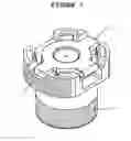
Shown in FIG. 7 is the integral cap sample cup with the alternative cap in the closed and locked position. Each locking tab (12) is shown mated to its corresponding slot (13). Also shown are the upwardly extending overflow chambers. Said overflow chambers extend vertically past the closed cap, providing increased surface area on the outside periphery of the upper body (2) to aid in gripping and manipulation of the sample cup. Further gripping means are indicated on the lower portion of outer member (11) in the area designated (11A) and along the outside periphery of the upper body (2).
Shown in FIG. 8 is a side view of the integral cap sample cup with the alternative cap in the closed position. The callout (16) highlights one embodiment of the described mechanism securing the integral cap to the upper body of the sample cup.
Shown in FIG. 9 is an enlarged view of the FIG. 8 callout. The hooked portion (14) of a locking tab (12) is shown mated to the hooked portion (15) of its corresponding slot (13), located on upper body (2). It is understood that the hooked portion (15) of a slot may be positioned along its outer wall (17) or inner wall (18) with the hooked portion (14) of a locking tab (12) being positioned to mate accordingly.
While the dimensions and shape of the sample cup components is not specifically defined and/or discussed herein, it is understood that such dimensions and shape may be adjusted or modified to meet industry needs or requirements without digressing from the spirit of the invention.
Claims
What is claimed:1. A sample cup for retaining a sample to be analyzed spectrochemically, said sample cup comprising:
a substantially cylindrical lower body with a bottom open end and integral upper body having a top open end and creating a flanged intersection with said lower body;
an integral cap secured to said upper body by a hinge;
an inner chamber suspended from said upper body into the interior of said lower body;
said inner chamber comprising a cutout and a bottom stop;
an outer member dimensioned to frictionally fit over said lower body; and
wherein a thin-film of material is secured across said bottom open end of said lower body by application of said outer member to contain a liquid sample for spectrochemical analysis.
2. The sample cup according to claim 1, further comprising an overflow chamber positioned along the top of said upper body.
3. The sample cup according to claim 2, wherein said overflow chamber extends vertically beyond said integral cap when said integral cap is in a closed position.
4. The sample cup according to claim 1, further comprising a pull tab integral with said cap.
5. The sample cup according to claim 1, further comprising a vent hole in said integral cap.
6. The sample cup according to claim 1, further comprising an upper body dimensioned to contain said integral cap flush with the top edge of said upper body when said integral cap is in the closed position.
7. The sample cup according to claim 1, further comprising an upper body dimensioned to include parallel opposing flat surfaces disposed perpendicular to said top open end of said upper body.
8. The sample cup according to claim 1, wherein said outer member includes a gripping means situated on a lower portion of said outer member to facilitate handling of the assembled sample cup.
9. The sample cup according to claim 2, further comprising a first channel extending from the top outside edge of said inner chamber to said overflow chamber.
10. The sample cup according to claim 2, further comprising a second channel situated at least partially circumferentially about the upper body top open end.
11. The sample cup according to claim 1, further comprising a second channel situated at least partially circumferentially about the upper body top open end.
12. The sample cup according to claim 1, further comprising a gripping means on said upper body.
13. A sample cup for retaining a sample to be analyzed spectrochemically, said sample cup comprising:
a substantially cylindrical lower body with a bottom open end and integral upper body having a top open end and creating a flanged intersection with said lower body;
an integral cap secured to said upper body by a hinge;
said integral cap including two or more downward projecting locking tabs, each locking tab dimensioned to fit within a corresponding slot in said upper body;
an inner chamber suspended from said upper body into the interior of said lower body;
said inner chamber comprising a cutout and a bottom stop;
an outer member dimensioned to frictionally fit over said lower body; and
wherein a thin-film of material is secured across said bottom open end of said lower body by application of said outer member to contain a liquid sample for spectrochemical analysis.
14. The sample cup according to claim 13, further comprising an overflow chamber positioned along the top of said upper body.
15. The sample cup according to claim 14, wherein said overflow chamber extends vertically beyond said integral cap when said integral cap is in a closed position.
16. The sample cup according to claim 13, further comprising a pull tab integral with said cap.
17. The sample cup according to claim 13, further comprising a vent hole in said integral cap.
18. The sample cup according to claim 13, further comprising an upper body dimensioned to contain said integral cap flush with the top edge of said upper body when said integral cap is in the closed position.
19. The sample cup according to claim 13, further comprising an upper body dimensioned to include parallel opposing flat surfaces disposed perpendicular to said top open end of said upper body.
20. The sample cup according to claim 13, wherein said outer member includes a gripping means situated on a lower portion of said outer member to facilitate handling of the assembled sample cup.
21. The sample cup according to claim 14, further comprising a first channel extending from the top outside edge of said inner chamber to said overflow chamber.
22. The sample cup according to claim 14, further comprising a second channel situated at least partially circumferentially about the upper body top open end.
23. The sample cup according to claim 13, further comprising a second channel situated at least partially circumferentially about the upper body top open end.
24. The sample cup according to claim 13, further comprising a gripping means on said upper body.
Images & Drawings included:


Sources:
- United States Patent and Trademark Office - verify current appl. status at the USPTO↗
Similar patent applications:
- » 20170146470
Sample Cup Inner Member with Integral Venting Cap
Recent applications in this class:
- » 20250288988 2025-09-18
SYSTEMS AND METHODS FOR COVERING AND SEALING AN OPEN WELL - » 20250269367 2025-08-28
DEVICE FOR ANALYZING AN AQUATIC POLLUTANT AND/OR A LIVING ORGANISM AND USES THEREFOR - » 20250262616 2025-08-21
LOW PRESSURE PLASMA MODIFIED PLASTIC HEMATOCRIT TUBE - » 20250222448 2025-07-10
DEVICE FOR COLLECTING BIOLOGICAL SAMPLES - » 20250196127 2025-06-19
APPARATUS FOR INVESTIGATING CHEMICAL PROCESSES IN PLATE-LIKE CELLS - » 20250177968 2025-06-05
TWO-DIMENSIONAL MATRIX DROPLET ARRAY - » 20250153162 2025-05-15
DUAL-COMPONENT SYSTEM AND DEVICE FOR PROCESSING AND ANALYZING POLYMERASE CHAIN REACTIONS WITHIN A CARTRIDGE AND CORRESPONDING METHODS OF USE - » 20250153161 2025-05-15
DISPOSABLE FLUID CASSETTE FOR FLUID MANAGEMENT SYSTEM - » 20250144617 2025-05-08
REMOVING AND REINSERTING PROTEIN NANOPORES IN A MEMBRANE USING OSMOTIC IMBALANCE - » 20250144616 2025-05-08
FILTRATION SAMPLING AND TESTING DEVICES
Recent applications for this Assignee:
- » 20170146470 2017-05-25
Sample Cup Inner Member with Integral Venting Cap - » 20170146469 2017-05-25
Oxford Style Sleeve for Sample Cup - » 20170089848 2017-03-30
Oxford style sample cup - » 20170056875 2017-03-02
Thin film envelope