Sample Cup Inner Member with Integral Venting Cap
US20170146470A1
2017-05-25
15/427,622
2017-02-08
Abstract:
This invention relates to the design and construction of a novel sample cup inner member including an integral venting cap for use in XRF Spectroscopy.
Assignee:
- Premier Lab Supply Inc. 5 🇺🇸 Port St. Lucie, FL, United States
Interested in similar patents?
Get notified when new applications in this technology area are published.
Classification:
G01N23/2204 » CPC main
Investigating or analysing materials by the use of wave or particle radiation, e.g. X-rays or neutrons, not covered by groups – , or by measuring secondary emission from the material Specimen supports therefor; Sample conveying means therefore
B65D43/169 » CPC further
Lids or covers for rigid or semi-rigid containers; Non-removable lids or covers hinged for upward or downward movement the container and the lid being made separately the lid, the hinge and the element connecting them to the container being made of one piece
B01L3/508 » CPC further
Containers or dishes for laboratory use, e.g. laboratory glassware ; Droppers; Containers for the purpose of retaining a material to be analysed, e.g. test tubes rigid containers not provided for above
B01L2300/048 » CPC further
Additional constructional details; Closures and closing means; Function or devices integrated in the closure enabling gas exchange, e.g. vents
G01N2223/307 » CPC further
Investigating materials by wave or particle radiation; Accessories, mechanical or electrical features cuvettes-sample holders
G01N23/22 IPC
Investigating or analysing materials by the use of wave or particle radiation, e.g. X-rays or neutrons, not covered by groups – , or by measuring secondary emission from the material
G01N23/223 » CPC further
Investigating or analysing materials by the use of wave or particle radiation, e.g. X-rays or neutrons, not covered by groups – , or by measuring secondary emission from the material by irradiating the sample with X-rays or gamma-rays and by measuring X-ray fluorescence
B01L3/00 IPC
Containers or dishes for laboratory use, e.g. laboratory glassware ; Droppers
B65D43/16 IPC
Lids or covers for rigid or semi-rigid containers; Non-removable lids or covers hinged for upward or downward movement
B65D47/32 » CPC further
Closures with filling and discharging, or with discharging, devices; Closures with discharging devices other than pumps with means for venting
Description
FIELD OF THE INVENTION
This invention relates to the design and construction of a novel sample cup inner member including an integral venting cap for use in XRF Spectroscopy.
BACKGROUND OF THE INVENTION
The present invention describes a novel sample cup inner member for use in XRF Spectroscopy.
Spectroscopic analysis (XRF Spectroscopy) utilizes sample cups to contain liquid or powder samples for elemental analysis. Sample cups generally have a thin transparent film bottom and may include a top end formed integral with the cup body known as a single ended design. Alternatively, the sample cup may include a second thin film or be secured at the top end, known as a double open end design. Sample cups are generally delivered to the analyst in parts comprised of a side wall member and complementary secondary member, which members are assembled in combination with a separate thin film component to construct a single sample cup. The sample cup, with its liquid or powder sample contained therein, is then manually transported to an XRF instrument and placed in a holder, thin film bottom down, for analysis.
In many instances, a liquid sample is deposited in a sample cup. A sample cup design utilizing a separate cap assembly to be manually applied to the sample cup body after deposit of the sample into the sample cup body requires manipulating the sample cup body, sample deposit via pipette and cap assembly. This creates handling problems and opportunities for contamination of the sample and contamination or damage to the thin film assembled to the bottom of the sample cup. The ability to reduce the number of manipulated items increases technician productivity and reduces the opportunities for contamination or damage to the sample cup and sample specimen.
In certain instances, provisions for venting may be necessary where a tested sample vents liquids or gases. Capped sample cups may contain a permanent vent hole to the outside atmosphere or a snap-off vent hole, also venting to the outside atmosphere. Venting is not always necessary or preferred particularly if the known sample is in the form of a loose powder; however and so a versatile sample cup capable of serving a venting or non-venting application constitutes a superior design.
In the case of violently venting liquids or gases, overflow chambers have been designed into sample cup designs to contain any venting liquids and prevent contamination or damage to the instrumentation. Existing design overflow chambers however, are limited by the sidewall and reservoir dimensions with a larger overflow chamber thereby reducing the sample reservoir capacity. Furthermore, liquid overflow displaced to existing design overflow chambers cannot be recycled or returned to the sample reservoir for testing. A superior design would provide for a larger overflow capacity without reducing the cross-sectional capacity of the sample reservoir, allow for return of vented liquids to the sample reservoir, and fully contain all liquids and gases within the capped and sealed sample cup.
The present invention addresses these concerns, being easily manipulated with one hand while providing superior venting options.
BRIEF DESCRIPTION OF THE DRAWINGS
FIGS. 1-6 are various views (perspective and elevation) of the Oxford style sample cup.
DETAILED DESCRIPTION OF THE INVENTION
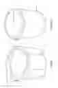
Shown in FIG. 1 is an outer member (1) with a top open end (shown) and a bottom open end (not shown). The outer member is dimensioned to frictionally fit circumferentially about inner member (2), shown in FIG. 2. Outer member is distinguished by a flanged upper rim (3), first projections (4) about the flanged upper rim, a lower body and second projections (5) about said lower body.
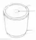
Shown in FIG. 2 is inner member (2) with a top closed end (not shown) and bottom open end. Inner member (2) is shown with a hinged cap (6) in the closed position. A center portion (9) is designed to be depressed to vent said inner top closed end.
Shown in FIG. 3 is the outer member (1) assembled in position over inner member (2).
Shown in FIG. 4 is outer member (1) partially assembled on inner member (2). In practice, a thin film would be placed between outer member (1) and inner member (2), the thin film dimensioned to cover the bottom open end of inner member (2) such that, upon assembly, a liquid sample would be retained for spectroscopic analysis. The first projections (4) may be dimensioned such that when the sample cup is assembled on a hard surface, such as a tabletop, the first projections will contact the tabletop when outer member is fully assembled over inner member. In at least one embodiment, this may result in approximately 0.005″ clearance between the thin film covering the bottom open end of said inner member and a planar surface when the sample cup assembly is returned to an upright position, as illustrated in FIG. 3. Said flanged upper rim (3) and second projections (5) of outer member (1) may assist in gripping and manipulating the outer member during assembly and handling for testing.
Shown in FIG. 5 is a bottom elevation view of outer member (1). Apparent in this view is the flanged upper rim (3), the lower body and second projections (5) about said lower body.
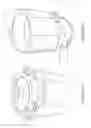
Shown in FIG. 6 is a perspective view of inner member (2) with hinged cap (6) in the open position. The top closed end (8) is shown disposed from the top wall edge of inner member (2), creating a space defined by the inner walls of inner member (2), top closed end (8) and hinged cap (6). This results in a dual chamber sample cup; the primary or testing chamber being defined by the inner walls of inner member (2), top closed end (8) and a thin film dimensioned to cover the previously bottom open end; and the secondary or venting chamber defined by the inner walls of inner member (2), top closed end (8) and hinged cap (6).
Protrusion (7) is dimensioned to allow hinged cap (6) to be placed in a closed position without piercing the top closed end (8) of inner member (2). In practice, when hinged cap (6) is in a closed position, a sample has been deposited and the sample cup has been fully assembled in preparation for testing, hinged cap (6) may be manually depressed thereby causing protrusion (7) to pierce the top closed end (8) to allow venting of liquids and gases into the space defined by the inner walls of inner member (2), top closed end (8) and hinged cap (6).
While the dimensions and shape of the sample cup components are not specifically defined and/or discussed herein, it is understood that such dimensions and shape may be adjusted or modified to meet industry needs or requirements without digressing from the spirit of the invention.
Claims
What is claimed:1. A sample cup inner member for retaining a sample to be analyzed spectrochemically, said inner member comprising:
a top closed end, a bottom open end, a cap, and including a protrusion situated on an inner surface of said cap to facilitate venting of an assembled sample cup when the top surface of said cap is depressed.
2. The sample cup inner member according to claim 1, wherein said top closed end is disposed from a top wall edge of said inner member.
3. The sample cup inner member according to claim 1, wherein said cap is integrally hinged about the top wall edge of said inner member.
4. The sample cup inner member according to claim 2, wherein said cap is integrally hinged about the top wall edge of said inner member.
5. The sample cup inner member according to claim 1, wherein said cap sits flush with the top wall edge of said inner member when assembled.
6. The sample cup inner member according to claim 2, wherein said cap sits flush with the top wall edge of said inner member when assembled.
7. The sample cup inner member according to claim 3, wherein said cap sits flush with the top wall edge of said inner member when assembled.
Images & Drawings included:

Sources:
- United States Patent and Trademark Office - verify current appl. status at the USPTO↗
Recent applications in this class:
- » 20250067690 2025-02-27
ANALYSIS SYSTEM, ANALYSIS DEVICE, AND CONTROL METHOD - » 20250003897 2025-01-02
Substrate Alloy Influence Compensation - » 20240369504 2024-11-07
INTEGRATED FESEM AND LDI-TOF-MS ANALYSIS SYSTEM - » 20240125716 2024-04-18
XPS SAMPLE HOLDER, APPARATUS FOR X-RAY PHOTOELECTRON SPECTROSCOPY INCLUDING THE SAME AND METHOD FOR X-RAY PHOTOELECTRON SPECTROSCOPY USING THE SAME - » 20240085352 2024-03-14
Thin film damage detection function and charged particle beam device - » 20240027375 2024-01-25
AUTOMATED ANALYZER - » 20240003835 2024-01-04
Sample Holder Assembly for Optical Microscopy - » 20230408427 2023-12-21
Sample Container and Measuring Method - » 20230333032 2023-10-19
SAMPLE HOLDER FOR DETECTION OF HYDROGEN PERMEATION AND HYDROGEN PERMEATION AND DIFFUSION PATH OBSERVATION DEVICE - » 20230204525 2023-06-29
Method and system for positioning and transferring a sample
Recent applications for this Assignee:
- » 20170146469 2017-05-25
Oxford Style Sleeve for Sample Cup - » 20170089848 2017-03-30
Oxford style sample cup - » 20170080415 2017-03-23
Integral cap sample cup - » 20170056875 2017-03-02
Thin film envelope