Chain-Connected Micro-Areal Vehicles
US20170101177A1
2017-04-13
15/313,085
2015-01-15
Abstract:
This invention proposes a method which enables one to combine several autonomous areal vehicles into a larger areal vehicle.
In particular, the proposed method enables arranging areal vehicles in a joint formation whereby a number of winged sections is joined horizontally and the flapping of the wings between the sections is coordinated in such a manner as to increase the lift-to-drag ratio. Changing the angle between the sections during the flight is done to increase the maneuverability of the vehicle.
Inventors:
- Andrei Vladimirovitch Smirnov 1 🇺🇸 VIENNA, VA, United States
- Michael Andrew Smirnoff 1 🇺🇸 Vienna, VA, United States
Interested in similar patents?
Get notified when new applications in this technology area are published.
Classification:
B64C39/024 » CPC further
Aircraft not otherwise provided for characterised by special use of the remote controlled vehicle type, i.e. RPV
B64C39/028 » CPC further
Aircraft not otherwise provided for characterised by special use Micro-sized aircraft
B64C2201/025 » CPC further
Unmanned aerial vehicles; Equipment therefor characterized by type of aircraft Ornithopters, i.e. generating lift and propulsion by flapping wings or insect like means
B64C37/02 » CPC main
Convertible aircraft Flying units formed by separate aircraft
B64C39/02 IPC
Aircraft not otherwise provided for characterised by special use
B64C33/00 » CPC further
Ornithopters
Description
TECHNICAL FIELD
This invention relates to the field of unmanned flying vehicles in general and micro-areal vehicles in particular.
BACKGROUND ART
Flight of several micro-areal vehicles (MAV) can be arranged in joined or disjoint manner. Swarms of MAVs often have to fly in a coordinated fashion to achieve mission objectives. Physically coupling or uncoupling of MAVs during the flight can be used to achieve a more economical flight over long distances as well as to increase lift force when transporting heavy loads.
DISCLOSURE OF INVENTION
Technical Problem
Micro areal vehicles suffer from two major limitations: (1) low lift force which limits their weight-lifting capabilities and (2) high relative drag forces which make it hard to overcome the wind force.
Solution to Problem
The above mentioned limitations of micro-areal vehicles can be overcome by arranging them in a joined formation. In particular, in the case of winged areal vehicles a number of winged sections is joined horizontally and the flapping of the wings is coordinated between the sections in a such a manner as to increase the lift-to-drag ratio and maneuverability of the formation.
Advantageous Effects of Invention
Proposed method of linking autonomous areal vehicles enables them to lift heavier loads than a single vehicle is capable of carrying. The method also reduces cumulative drag on the vehicles thereby extending the duration of the flight.
BRIEF DESCRIPTION OF DRAWINGS
FIG. 1: Coordinated wing flapping in a joined flight
FIG. 2: Front view of a single section
FIG. 3: Rear view of a single section
FIG. 4: Flexing body in a flight
MODES FOR CARRYING OUT THE INVENTION
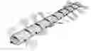
A mode of flying a wing-propelled vehicle described in claim 1 is shown in FIG. 1. In this mode an areal vehicle is equipped with multiple pairs of wings (26) and is capable of coordinated wing flapping so as to produce a coherent wave-like pattern. This type of propulsion is used in nature by sea creatures such as ribbon eels, sear horses, and infusorians. This method of wings flapping in conjunction with a joint flight will increase the total lift to drag ratio, thus enabling longer flight distances and make a vehicle more resistant to wind forces.
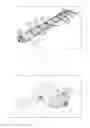
Embodiments of FIGS. 2 and 3 show the method of coupling multiple two-winged sections into a combined multi-winged section. This is done by means of special clams in the front (28) and in the rear (30) of the vehicle. In this joined formation a swarm of micro-areal vehicles flies on a long-distance mission and then uncouples at the destination.
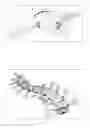
The embodiment of FIG. 4 demonstrates the possibility of flexing the shape of the combined multi-winged vehicle consisting of chain-linked double-winged sections as described in Claim 1. This will provide for a greater maneuverability of the vehicle.
INDUSTRIAL APPLICABILITY
Micro areal vehicles arranged in the manner suggested by the current invention can be used in such industrial applications as surveillance, retrieval, repair, delivery, toys, and large areas monitoring to name just a few.
REFERENCE SIGNS LIST
- 26. Wings
- 28. Front join mechanism
- 30. Rear join mechanism
Claims
1. An apparatus capable of autonomous flight, consisting of two sections joined one on top of the other and each section comprising:
(a) a vertical rotor shaft of a cylindrical shape with a central hole,
(b) a plurality of rotor blades attached to said rotor shaft,
(c) a vertical central axle extending through the central hole of said rotor shaft above said rotor blades,
(d) top joint clams at the top of said central axle for joining with the other section of the apparatus from the bottom,
(e) a horizontal bottom joint axle at the bottom for joining with said top joint clams of the other section of the apparatus.
(f) an axle tilt mechanism to rotate said bottom joint axle around its axis.
2. A method of enabling autonomous flight capability for a small areal vehicle, comprising:
(a) providing an autonomous areal vehicle equipped with a plurality of wings in a number greater than four,
(b) arranging a coordinated wing flapping whereby tip positions of all wings at each time form a wave-like pattern.
3. The method of claim 2 further comprising:
(a) making the fuselage of said vehicle consisting of separate winged sections, each section having at least one pair of wings and capable of autonomous flight,
(b) providing each said winged section with a front join mechanism, and a rear join mechanism for joining it with the other sections.
4. The method of claim 3 wherein the angle between two joined sections changes during the flight thereby increasing the maneuverability of the areal vehicle.
Images & Drawings included:
Sources:
- United States Patent and Trademark Office - verify current appl. status at the USPTO↗
Recent applications in this class:
- » 20250171141 2025-05-29
A Vertical Takeoff and Landing Assistance Aircraft using Fixed Angle Ducted Motors - » 20250074589 2025-03-06
AIRCRAFT SURVIVAL KIT GLIDER - » 20230227155 2023-07-20
MULTIPLE VEHICLE SYSTEM - » 20230015158 2023-01-19
Vertiports for Unmanned Arial Vehicles - » 20220363379 2022-11-17
Transportation system for transporting organic payloads - » 20220281597 2022-09-08
Method of navigating an amphibious aerial vehicle on water - » 20220281596 2022-09-08
Method of navigating an amphibious aerial vehicle on water - » 20220281595 2022-09-08
Amphibious aerial vehicle - » 20220063802 2022-03-03
QuadQuad: Scalable Multi Element Rotary Wing Aerial Vehicle - » 20220041280 2022-02-10
Amphibious aerial vehicle