Coating method
US20170108159A1
2017-04-20
15/127,104
2015-03-16
✅ Patent granted
US 9,976,688 B2
2018-05-22
WO; PCT/GB2015/050758; 20150316
WO; WO2015/140523; 20150924
Philip Tucker | Vicki Wu
Pearne & Gordon LLP
2035-03-16
Abstract:
A method of coating an expandable item (10) such as a pressure vessel or process vessel used for instance in the off shore oil industry. A compressible flexible intermediate layer (14) is provided on the item (10), and a support member (18) is embedded in the intermediate layer (14). The support member (18) comprises an open framework base (20) and a plurality of projecting members upstanding therefrom and extending out of the intermediate layer (14) away from the item (10). A thermally insulating coating layer (12) is applied over the intermediate layer (14) such that the projecting members (22) extend into the coating layer (12), and are wholly located in the coating layer (12).
Assignee:
- Advanced Insulation PLC 1 🇬🇧 Gloucestershire, United Kingdom
- ADVANCED INSULATION PLC 1 🇬🇧 Gloucester, United Kingdom
Applicant:
Interested in similar patents?
Get notified when new applications in this technology area are published.
Classification:
F16L59/029 » CPC main
Thermal insulation in general; Shape or form of insulating materials, with or without coverings integral with the insulating materials layered
B32B3/263 » CPC further
Layered products comprising a layer with external or internal discontinuities or unevennesses, or a layer of non-planar form ; Layered products having particular features of form characterised by a particular shape of the outline of the cross-section of a continuous layer; characterised by a layer with cavities or internal voids ; characterised by an apertured layer characterised by a layer having non-uniform thickness
B32B3/266 » CPC further
Layered products comprising a layer with external or internal discontinuities or unevennesses, or a layer of non-planar form ; Layered products having particular features of form characterised by a particular shape of the outline of the cross-section of a continuous layer; characterised by a layer with cavities or internal voids ; characterised by an apertured layer characterised by an apertured layer, the apertures going through the whole thickness of the layer, e.g. expanded metal, perforated layer, slit layer regular cells
B32B15/046 » CPC further
Layered products comprising a layer of metal comprising metal as the main or only constituent of a layer, next to another layer of a of foam
B32B27/065 » CPC further
Layered products comprising synthetic resin as the main or only constituent of a layer, next to another layer of a of foam
B32B27/285 » CPC further
Layered products comprising synthetic resin comprising synthetic resins not wholly covered by any one of the sub-groups - comprising polyethers
B32B37/182 » CPC further
Methods or apparatus for laminating, e.g. by curing or by ultrasonic bonding characterised by the properties of the layers with all layers existing as coherent layers before laminating involving the assembly of discrete sheets or panels only one or more of the layers being plastic
B32B2250/02 » CPC further
Layers arrangement 2 layers
B32B2255/06 » CPC further
Coating on the layer surface on metal layer
B32B2255/10 » CPC further
Coating on the layer surface on synthetic resin layer or on natural or synthetic rubber layer
B32B2255/102 » CPC further
Coating on the layer surface on synthetic resin layer or on natural or synthetic rubber layer synthetic resin or rubber layer being a foamed layer
B32B2255/26 » CPC further
Coating on the layer surface Polymeric coating
B32B2266/0214 » CPC further
Composition of foam; Organic Materials belonging to
B32B2307/304 » CPC further
Properties of the layers or laminate having particular thermal properties Insulating
B32B2307/3065 » CPC further
Properties of the layers or laminate having particular thermal properties; Resistant to heat Flame resistant or retardant, fire resistant or retardant
B32B2307/734 » CPC further
Properties of the layers or laminate; Other properties; Dimensional properties Dimensional stability
B32B2311/00 » CPC further
Inorganic materials used for the layers, laminate or apparatus components
B32B2311/00 » CPC further
Metals, their alloys or their compounds
B32B2311/30 » CPC further
Metals, their alloys or their compounds Iron, e.g. steel
B32B2323/04 » CPC further
Polyalkenes Polyethylene
B32B2371/00 » CPC further
Polyethers, e.g. PEEK, i.e. polyether-etherketone; PEK, i.e. polyetherketone
B32B2375/00 » CPC further
Polyureas; Polyurethanes
B32B2377/00 » CPC further
Polyamides
B32B2439/40 » CPC further
Containers; Receptacles Closed containers
F16L59/02 IPC
Thermal insulation in general Shape or form of insulating materials, with or without coverings integral with the insulating materials
B32B7/12 » CPC further
Layered products characterised by the relation between layers; Layered products characterised by the relative orientation of features between layers, or by the relative values of a measurable parameter between layers, i.e. products comprising layers having different physical, chemical or physicochemical properties; Layered products characterised by the interconnection of layers; Interconnection of layers using interposed adhesives or interposed materials with bonding properties
B32B15/095 » CPC further
Layered products comprising a layer of metal comprising metal as the main or only constituent of a layer, next to another layer of a of synthetic resin comprising polyurethanes
B32B27/28 IPC
Layered products comprising synthetic resin comprising synthetic resins not wholly covered by any one of the sub-groups -
B32B3/26 IPC
Layered products comprising a layer with external or internal discontinuities or unevennesses, or a layer of non-planar form ; Layered products having particular features of form characterised by a particular shape of the outline of the cross-section of a continuous layer; characterised by a layer with cavities or internal voids ; characterised by an apertured layer
B32B27/06 IPC
Layered products comprising synthetic resin as the main or only constituent of a layer, next to another layer of a
B32B27/34 » CPC further
Layered products comprising synthetic resin comprising polyamides
B32B15/04 IPC
Layered products comprising a layer of metal comprising metal as the main or only constituent of a layer, next to another layer of a
B32B1/02 » CPC further
Layered products having a general shape other than plane Receptacles, i.e. rigid containers , e.g. tanks
B32B27/08 » CPC further
Layered products comprising synthetic resin as the main or only constituent of a layer, next to another layer of a of synthetic resin
B32B15/085 » CPC further
Layered products comprising a layer of metal comprising metal as the main or only constituent of a layer, next to another layer of a of synthetic resin comprising polyolefins
B32B37/18 IPC
Methods or apparatus for laminating, e.g. by curing or by ultrasonic bonding characterised by the properties of the layers with all layers existing as coherent layers before laminating involving the assembly of discrete sheets or panels only
B32B37/12 » CPC further
Methods or apparatus for laminating, e.g. by curing or by ultrasonic bonding characterised by using adhesives
B32B27/40 » CPC further
Layered products comprising synthetic resin comprising polyurethanes
B32B15/18 » CPC further
Layered products comprising a layer of metal comprising iron or steel
B32B5/18 » CPC further
Layered products characterised by the non- homogeneity or physical structure, i.e. comprising a fibrous, filamentary, particulate or foam layer; Layered products characterised by having a layer differing constitutionally or physically in different parts characterised by features of a layer of foamed material
B32B27/32 » CPC further
Layered products comprising synthetic resin comprising polyolefins
B32B15/08 » CPC further
Layered products comprising a layer of metal comprising metal as the main or only constituent of a layer, next to another layer of a of synthetic resin
B32B2250/24 » CPC further
Layers arrangement All layers being polymeric
B32B2383/00 » CPC further
Polysiloxanes
B32B38/10 » CPC further
Ancillary operations in connection with laminating processes Removing layers, or parts of layers, mechanically or chemically
Description
This invention concerns a method of coating an expandable item, and typically for example coating a pressure or process vessel which may thermally expand and contract during use.
Pressure or process vessels which may typically be made of steel but can be made of other materials, can expand and contract quite significantly during use as a result of changing temperatures within. It is often desired or required to provide an insulating and/or fireproof coating on such vessels. As such coatings will not expand to anything like the same degree as the vessels during heating up and cooling down, it is generally necessary to provide an intermediate layer between the vessel and coating. Difficulties however can be encountered in adhering such layers together, and particularly the materials, used often have low surface energy and therefore do not readily adhere together.
According to the present invention there is provided a method of coating an expandable item, the method including forming a flexible intermediate layer, the intermediate layer including a support member located within a layer of a compressible flexible material, with a plurality of projecting members provided on the support member which extend out of the layer of compressible flexible material on one side thereof, mounting the flexible intermediate layer on the item, with the other side of the layer of compressible flexible material against the item and the projecting members projecting away from the item, and forming a coating layer on the one side of the flexible intermediate layer, with the projecting members extending into the coating layer, and the coating layer extending beyond the projecting members such that distal ends of the projecting members are wholly located in the coating layer.
The support member may include a base which may be in the form of an open framework, and may be generally planar. The base may be located in the layer of compressible flexible material, and may be located at least generally midway between the one side and other side of the layer of compressible flexible material.
The support member base may be made of a flexible material. The support member base may be made of a plastics material and may be made of PEEK or nylon. Alternatively the support member base may be made of metal and may be made of stainless steel.
In one arrangement the support member base and projecting members are integrally formed.
In a further arrangement the projecting members may be mounted on the support member base.
The projecting members may have formations thereon to enhance engagement with the coating layer. The formations may include any of a helical thread, ribs, barbs or other formations.
The support members may be formed in sections which can be connected together with adjacent such sections.
The compressible flexible material may comprise a foamed material which may be any of a polyethylene, polyurethane or silicone foam. The foamed material may be syntactic.
The compressible flexible material may be non-flammable.
The layer of compressible flexible material may be between 3 and 10 mm thick.
The flexible intermediate layer may be formed by moulding the compressible flexible material around the support member.
An adhesive may be provided on the other side of the flexible intermediate layer, and the adhesive may be pressure actuable, and may be provided with a backing sheet prior to mounting on the item.
The coating layer may be thermally insulating and/or non-flammable.
The coating layer may be applied wet onto the flexible intermediate layer, and allowed to cure in situ.
The coating layer may be a foamed material and may be of any phenolic, epoxy or polyurethane. The foamed material may be syntactic.
The coating layer may be between 10 and 100 mm thick.
The vessel may be made of metal or composite material. The vessel may be a pressure or process vessel.
The invention further provides an item coated with a method according to any of the preceding seventeen paragraphs.
An embodiment of the present invention will now be described by way of example only and with reference to the accompanying drawings, in which:
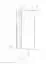
FIG. 1 is a diagrammatic cross sectional view through part of an item coated by a method according to the present invention; and
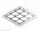
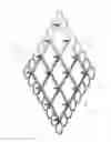
FIG. 2 is a perspective view of part of the coating shown in FIG. 1.
FIG. 1 shows part of an item 10 with a coating 12 applied thereto. The item 10 may be a pressure vessel or process vessel used for instance in the offshore oil industry. In use this vessel may experience a significant range of working temperatures, for instance between −196° and 250°. Such heating and cooling can cause the vessel 10 to expand or contract for instance by up to 1 mm.
The coating 12 comprises an intermediate layer 14 and a coating layer 16. The intermediate layer 14 comprises a layer of a compressible flexible material such as syntactic silicone foam, including compressible micro spheres, and may be 4 mm thick.
A support member 18 is embedded in the intermediate layer 14. The support member is best shown in FIG. 2, and comprises a base 20 in the form of an open framework, and portions of the base 20 can be interconnected to adjacent such portions. A plurality of projecting members 22 are upstanding as shown in FIG. 1 from the base 20, and extend out of one side of the intermediate layer 14. The projecting members 22 have a formation thereon to engage with the coating layer 16. In this instance the formation is a helical thread 24.
The coating layer is for instance around 16 mm thick and may be made of a thermally insulating material which may also be non-flammable. In this instance the coating layer 16 is a syntactic phenolic foam.
In use the item 10 can be coated as follows. Firstly the intermediate layer 14 is formed. This is formed by moulding the compressible flexible layer around the support member 18, such that the base 20 of the support member 18 is generally in the middle of the intermediate layer 14, with the projecting members 12 extending outwardly therefrom on one side.
A pressure sensitive adhesive may be applied on the side of the intermediate layer 14 through which the projecting members 22 do not extend, and this can be provided with a backing paper. The intermediate layer 14 can be mounted on the item 10 using the adhesive following removal of the backing paper, and sheets of the intermediate layer 14 can be cut to size and shape as required.
The coating layer 16 can then be applied wet onto the outside of the intermediate layer 14. The projecting members 22 help to bond the intermediate and coating layers 14, 16 together, which otherwise would not form a strong bond therebetween.
In use as the item 10 expands or contracts due to different temperatures, the intermediate layer 14 can be compressed between the item 10 and coating layer 16, or in some instances extended, thereby absorbing the different rates of thermal expansion between the item 10 and the coating layer 16, which layer 16 would generally have a relatively low coefficient of thermal expansion.
There is thus described a method of coating an expandable item with for instance insulating and/or non-flammable material which provides for an advantageous arrangement, and particularly readily permits the intermediate and coating layers to be interconnected to provide a strong bond therebetween which otherwise can be difficult to achieve. As the coating layer is applied wet, this can be applied around different shapes, and in situations where access may be limited.
Various modifications may be made without departing from the scope of the invention. For instance, the support member may take a different form, and the base and projector members may be integrally formed, or can be separate components mounted together. Different formations may be provided on the projecting members such as ribs or barbs. The coating layer may be made of different material and could for instance be an epoxy or polyurethane based foam.
The method could be used to coat different items, and these items could be made of a composite material rather than metal. Different materials may be used in the intermediate layer and these could comprise non syntactic foams, polyethylene or polyurethane foams.
Whilst endeavouring in the foregoing specification to draw attention to those features of the invention believed to be of particular importance it should be understood that the Applicant claims protection in respect of any patentable feature or combination of features hereinbefore referred to and/or shown in the drawings whether or not particular emphasis has been placed thereon.
Claims
1. A method of coating an expandable item, the method including forming a flexible intermediate layer, the intermediate layer including a support member located within a layer of a compressible flexible material, with a plurality of projecting members provided on the support member which extend out of the layer of compressible flexible material on one side thereof, mounting the flexible intermediate layer on the item, with the other side of the layer of compressible flexible material against the item and the projecting members projecting away from the item, and forming a coating layer on the one side of the flexible intermediate layer, with the projecting members extending into the coating layer, and the coating layer extending beyond the projecting members such that distal ends of the projecting members are wholly located in the coating layer.
2. A method according to claim 1, in which the support member includes a base.
3. A method according to claim 2, in which the base is in the form of an open framework.
4. A method according to claim 2, in which the base is generally planar.
5. A method according to claim 2, in which the base is located in the layer of compressible flexible material.
6. A method according to claim 5, in which the base is located at least generally midway between the one side and other side of the layer of compressible flexible material.
7. A method according to claim 2, in which the support member base is made of any of a flexible material, plastics material, PEEK or nylon, metal, stainless steel.
8-11. (canceled)
12. A method according to claim 2, in which either the support member base and projecting members are integrally formed, or the projecting members are mounted on the support member base.
13. (canceled)
14. A method according to claim 1, in which the projecting members have formations thereon to enhance engagement with the coating layer, the formations including any of a helical thread, ribs or barbs.
15. (canceled)
16. A method according to claim 1, in which the support members are formed in sections which can be connected together with adjacent such sections.
17. A method according to claim 1, in which the compressible flexible material comprises any of a foamed material, polyethylene, polyurethane, silicone foam, a syntactic material, a non-flammable material.
18-20. (canceled)
21. A method according to claim 1, in which the layer of compressible flexible material is between 3 and 10 mm thick, and/or the coating layer is between 10 and 100 mm thick.
22. A method according to claim 1, in which the flexible intermediate layer is formed by moulding the compressible flexible material around the support member.
23. A method according to claim 1, in which an adhesive is provided on the other side of the flexible intermediate layer, the adhesive is pressure actuable, and the adhesive is provided with a backing sheet prior to mounting on the item.
24-25. (canceled)
26. A method according to claim 1, in which the coating layer is thermally insulating, and non-flammable.
27. (canceled)
28. A method according to claim 1, in which the coating layer is applied wet onto the flexible intermediate layer, and allowed to cure in situ.
29. A method according to claim 1, in which the coating layer is a foamed material, phenolic, epoxy, polyurethane, syntactic.
30-32. (canceled)
33. A method according to claim 1, in which the vessel is made of metal or composite material.
34. A method according to claim 1, in which the vessel is a pressure or process vessel.
35. An expandable item coated by a method, the method including forming a flexible intermediate layer, the intermediate layer including a support member located within a layer of a compressible flexible material, with a plurality of projecting members provided on the support member which extend out of the layer of compressible flexible material on one side thereof, mounting the flexible intermediate layer on the item, with the other side of the layer of compressible flexible material against the item and the projecting members projecting away from the item, and forming a coating layer on the one side of the flexible intermediate layer, with the projecting members extending into the coating layer, and the coating layer extending beyond the projecting members such that distal ends of the projecting members are wholly located in the coating layer.
36-38. (canceled)
Images & Drawings included:
Sources:
- United States Patent and Trademark Office - verify current appl. status at the USPTO↗
Similar patent applications:
- » 20160121367
Clear coating method, coating method, and coating film structure - » 20110052829
COATING METHOD, COATING STATION, AND METHOD FOR COATING AN OBJECT - » 20190060945
Coating method, coating apparatus for carrying out this method and coating unit with such a coating apparatus - » 20170014601
Balloon coating method, coat layer control method and balloon coating device - » 20250253374
JOINED BASE MATERIAL, PEELING METHOD, COATING METHOD, PEELING DEVICE, COATING DEVICE, AND BASE MATERIAL CONNECTING METHOD - » 20140161981
Polyurethane coating material composition, multistage coating methods using these coating material compositions, and also the use of the coating material composition as clearcoat material and pigmented coating material, and application of the coating method for automotive refinish and/or for the coating of plastics substrates and/or of utility vehicles - » 20140308451
Polyurethane coating material composition, multistage coating methods using these coating material compositions, and also the use of the coating material composition as clearcoat material and pigmented coating material, and application of the coating method for automotive refinish and/or for the coating of plastics substrates and/or of utility vehicles - » 20140322448
Polyurethane coating agent composition, multistage coating method using said coating agent compositions, and use of the coating agent compositions as clear coating or pigmented coating material, and use of the coating method for automotive repair painting and/or for coating plastics substrates and/or of commercial vehicles - » 20130014386
MOUNTING APPARATUS, COATING APPARATUS, MOUNTING METHOD, COATING METHOD, AND PROGRAM - » 20060159855
Blade coating method and disk coating method using the same
Recent applications in this class:
- » 20250290592 2025-09-18
MOLDING SYSTEM FOR INSULATED PIPE - » 20250198560 2025-06-19
PIPE FOR CONVEYING FLUIDS IN HVACR SYSTEMS AND COMPOSITE COATING FOR SUCH A PIPE - » 20250137571 2025-05-01
Thermal Insulation System for Exhaust Gas Temperature Management - » 20250084950 2025-03-13
DEVICE FOR THE TEMPERATURE CONTROL OF FLUIDS - » 20240271741 2024-08-15
HEAT INSULATION AND REJECTION PROTECTOR - » 20240159348 2024-05-16
METAL-BASED THERMAL INSULATION STRUCTURES - » 20240044440 2024-02-08
Manufacture of Pipe-in-Pipe Assemblies - » 20240027015 2024-01-25
SEMI-NONCOMBUSTIBLE BUILDING THERMAL INSULATION MATERIAL AND MANUFACTURING METHOD THEREOF - » 20230175634 2023-06-08
Fabric jacket to prevent nonmetallic equipment from extreme heat, external damage and fire - » 20230137709 2023-05-04
SHIELDED cPVC PIPE AND BANDAGE