Shift control method for hybrid vehicle with DCT
US20170129494A1
2017-05-11
15/094,199
2016-04-08
✅ Patent granted
US 9,937,925 B2
2018-04-10
-
-
Jonathan M Dager
Brinks Gilson & Lione
2036-11-18
Abstract:
The present disclosure provides a shift control method for a hybrid vehicle with a DCT that includes: a shifting state-determining step in which a controller determines whether an inertia phase of power-off down-shift is entered; a motor torque-adjusting step that request to reduce regenerative braking torque of a motor as much as a predetermined requested reduction amount, when the controller determines that the inertia phase has been entered in the shifting state-determining step; and a clutch torque-reducing step that ends the motor torque-adjusting step and reduces torque of an engagement clutch, when the requested reduction amount of the regenerative braking torque of the motor is less than zero while the controller performs the motor torque-adjusting step.
Assignee:
- Hyundai Motor Company 20,646 🇰🇷 Seoul, South Korea
Applicant:
Interested in similar patents?
Get notified when new applications in this technology area are published.
Classification:
B60W30/18127 » CPC main
Purposes of road vehicle drive control systems not related to the control of a particular sub-unit, e.g. of systems using conjoint control of vehicle sub-units, or advanced driver assistance systems for ensuring comfort, stability and safety or drive control systems for propelling or retarding the vehicle; Propelling the vehicle related to particular drive situations; Braking Regenerative braking
B60K6/547 » CPC further
Arrangement or mounting of plural diverse prime-movers for mutual or common propulsion, e.g. hybrid propulsion systems comprising electric motors and internal combustion engines the prime-movers consisting of electric motors and internal combustion engines, e.g. HEVs; Architecture of the driveline characterised by arrangement or kind of transmission units; Transmission for changing ratio the transmission being a stepped gearing
B60W10/08 » CPC further
Conjoint control of vehicle sub-units of different type or different function including control of propulsion units including control of electric propulsion units, e.g. motors or generators
B60W10/113 » CPC further
Conjoint control of vehicle sub-units of different type or different function including control of change-speed gearings; Stepped gearings with two input flow paths, e.g. double clutch transmission selection of one of the torque flow paths by the corresponding input clutch
B60W20/15 » CPC further
Control systems specially adapted for hybrid vehicles; Controlling the power contribution of each of the prime movers to meet required power demand Control strategies specially adapted for achieving a particular effect
B60W30/19 » CPC further
Purposes of road vehicle drive control systems not related to the control of a particular sub-unit, e.g. of systems using conjoint control of vehicle sub-units, or advanced driver assistance systems for ensuring comfort, stability and safety or drive control systems for propelling or retarding the vehicle; Propelling the vehicle Improvement of gear change, e.g. by synchronisation or smoothing gear shift
B60K2006/4825 » CPC further
Arrangement or mounting of plural diverse prime-movers for mutual or common propulsion, e.g. hybrid propulsion systems comprising electric motors and internal combustion engines the prime-movers consisting of electric motors and internal combustion engines, e.g. HEVs characterised by the architecture of the hybrid electric vehicle; Parallel type Electric machine connected or connectable to gearbox input shaft
B60W20/00 » CPC further
Control systems specially adapted for hybrid vehicles
B60W2510/025 » CPC further
Input parameters relating to a particular sub-units; Clutches; Clutch slip, i.e. difference between input and output speeds Slip change rate
B60W2510/0275 » CPC further
Input parameters relating to a particular sub-units; Clutches Clutch torque
B60W2510/083 » CPC further
Input parameters relating to a particular sub-units; Electric propulsion units Torque
B60W2510/088 » CPC further
Input parameters relating to a particular sub-units; Electric propulsion units Inertia
B60W2510/102 » CPC further
Input parameters relating to a particular sub-units; Change speed gearings; Input shaft speed, e.g. turbine speed Input speed change rate
B60W2510/1095 » CPC further
Input parameters relating to a particular sub-units; Change speed gearings Inertia
B60W2540/10 » CPC further
Input parameters relating to occupants Accelerator pedal position
B60W2710/022 » CPC further
Output or target parameters relating to a particular sub-units; Clutches; Clutch engagement state Clutch actuator position
B60W2710/027 » CPC further
Output or target parameters relating to a particular sub-units; Clutches Clutch torque
B60W2710/083 » CPC further
Output or target parameters relating to a particular sub-units; Electric propulsion units Torque
F16H3/006 » CPC further
Toothed gearings for conveying rotary motion with variable gear ratio or for reversing rotary motion power being selectively transmitted by either one of the parallel flow paths
B60W30/00 IPC
Purposes of road vehicle drive control systems not related to the control of a particular sub-unit, e.g. of systems using conjoint control of vehicle sub-units, or advanced driver assistance systems for ensuring comfort, stability and safety or drive control systems for propelling or retarding the vehicle
B60W30/18 IPC
Purposes of road vehicle drive control systems not related to the control of a particular sub-unit, e.g. of systems using conjoint control of vehicle sub-units, or advanced driver assistance systems for ensuring comfort, stability and safety or drive control systems for propelling or retarding the vehicle Propelling the vehicle
B60K6/48 » CPC further
Arrangement or mounting of plural diverse prime-movers for mutual or common propulsion, e.g. hybrid propulsion systems comprising electric motors and internal combustion engines the prime-movers consisting of electric motors and internal combustion engines, e.g. HEVs characterised by the architecture of the hybrid electric vehicle Parallel type
B60W10/02 » CPC further
Conjoint control of vehicle sub-units of different type or different function including control of driveline clutches
F16H3/00 IPC
Toothed gearings for conveying rotary motion with variable gear ratio or for reversing rotary motion
Description
CROSS REFERENCE TO RELATED APPLICATION
The present application claims priority to and the benefit of Korean Patent Application No. 10-2015-0157192, filed Nov. 10, 2015, which is incorporated by reference in its entirety.
FIELD
The present disclosure relates to a shift control method for a hybrid vehicle with a Double Clutch Transmission (DCT).
BACKGROUND
The statements in this section merely provide background information related to the present disclosure and may not constitute prior art.
In a hybrid vehicle, regenerative braking using a motor is performed to increase fuel efficiency while a vehicle is decelerated, and the power generated in this process is returned as electric energy.
Further, when a vehicle brakes and decelerates, the vehicle speed decreases and the transmission performs down-shift, but in a hybrid vehicle with a DCT connected with a motor, it is desired to perform power-off down-shift simultaneously with regenerative braking.
As used herein, power-off down-shift generally means shifting to a lower gear step without pressing an acceleration pedal. Further, as used herein heavy breaking generally means braking with the brake pedal pressed by at least 30% of full brake stroke (i.e., 100% braking).
The foregoing is intended merely to aid in the understanding of the background of the present disclosure, and is not intended to mean that the present disclosure falls within the purview of the related art that is already known to those skilled in the art.
SUMMARY
The present disclosure proposes a shift control method for a hybrid vehicle with a DCT that may improve quality of shifting and accordingly improve the commercial value of a vehicle by quickly and smoothly performing power-off down-shift in heavy braking of a hybrid vehicle with a DCT connected with a motor.
Accordingly, the present disclosure proposes a shift control method for a hybrid vehicle with a DCT that includes: a shifting state-determining step in which a controller determines whether an inertia phase of power-off down-shift has been entered; a motor torque-adjusting step that requests to reduce regenerative braking torque of a motor as much as a predetermined requested reduction amount, when the controller determines that the inertia phase has been entered in the shifting state-determining step; and a clutch torque-reducing step that ends the motor torque-adjusting step and reduces torque of an engagement clutch, when the requested reduction amount of the regenerative braking torque of the motor is less than zero while the controller performs the motor torque-adjusting step.
The requested reduction amount for reducing the regenerative braking torque of the motor in the motor torque-adjusting step may be determined in accordance with the engagement clutch torque, the slip change rate of the engagement clutch, and the speed change rate of the engagement input shaft.
The requested reduction amount for reducing the regenerative braking torque of the motor in the motor torque-adjusting step may be determined by the following equation,
Requested reduction amount=−Tc+Jm*(dSlip/dt+dNi/dt)
where,
Tc; engagement clutch torque
Jm; moment of inertia of motor
Slip; slip amount of engagement clutch (=Nm−Ni)
Ni; speed of engagement input shaft
Nm; motor speed
In the clutch torque-reducing step, a reduction amount of the engagement clutch torque may be calculated in the same manner as the requested reduction amount calculated in the motor torque-adjusting step.
The controller may perform the shifting state-determining step that determines whether the inertia phase of power-off down-shift has been entered on the basis of engagement clutch torque, disengagement clutch torque, a motor speed, and an APS signal; may calculate the requested reduction amount in the motor torque-adjusting step and request a motor controller to reduce the regenerative braking torque as much as the requested reduction amount; and may stop the request for the motor controller to reduce the regenerative braking torque and reduce the engagement clutch torque by controlling a clutch actuator in the clutch torque-reducing step.
According to the present disclosure, it is possible to improve quality of shifting and accordingly improve the commercial value of a vehicle by quickly and smoothly performing power-off down-shift in heavy braking of a hybrid vehicle with a DCT connected with a motor.
Further areas of applicability will become apparent from the description provided herein. It should be understood that the description and specific examples are intended for purposes of illustration only and are not intended to limit the scope of the present disclosure.
DRAWINGS
In order that the disclosure may be well understood, there will now be described various forms thereof, given by way of example, reference being made to the accompanying drawings, in which:
FIG. 1 is a diagram showing the configuration of a hybrid vehicle with a DCT to which the present disclosure can be applied;
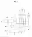
FIG. 2 is a flowchart illustrating one form of a shift control method for a hybrid vehicle with a DCT according to the present disclosure; and
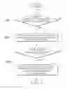
FIG. 3 is a graph illustrating a shift control method of a vehicle with a DCT according to the present disclosure.
The drawings described herein are for illustration purposes only and are not intended to limit the scope of the present disclosure in any way.
DETAILED DESCRIPTION
The following description is merely exemplary in nature and is not intended to limit the present disclosure, application, or uses. It should be understood that throughout the drawings, corresponding reference numerals indicate like or corresponding parts and features.
FIG. 1 is a diagram showing the configuration of a hybrid vehicle with a DCT to which the present disclosure can be applied, in which an engine clutch EC is disposed between an engine E and a motor M, the motor M is connected to driving wheels W through a DCT, the DCT includes two clutches 1, a clutch actuator 3 for operating the clutches 1, and a shifting actuator 4 for selecting gear steps, and a controller 5 controls the clutch actuator 3 and the shifting actuator 4.
The clutches 1 of the DCT are connected with input shafts 6, respectively, so in shifting, the input shaft and the clutch connected to the current shifted gear step are a disengagement input shaft and a disengagement clutch, and the input shaft and the clutch connected to a desired gear step are an engagement input shaft and an engagement clutch.
The motor M is controlled by a separate motor controller MC, so it is possible to control regenerative braking torque of the motor M in response to a request from the controller 5, which will be described below.
For reference, the term ‘controller’ simply stated herein means, for discrimination, a transmission controller that controls the clutch actuator 3 and the shifting actuator 4. The controller may include a computer, processor and/or electronic circuit that is programmed or arranged for controlling the clutch actuators.
The controller 5 and the motor controller MC are independent parts, but they may be implemented as a single controller.
The controller 5 can control the engine clutch EC and receive a signal from an APS (Accelerator Pedal Sensor, 7).
FIG. 2 is a flowchart illustrating one form of a shift control method for a hybrid vehicle with a DCT according to the present disclosure. The method includes: a shifting state-determining step in which the controller 5 determines whether an inertia phase of power-off down-shift has been entered (S10); a motor torque-adjusting step that requests to reduce regenerative braking torque of the motor M as much as a predetermined requested reduction amount (S20), when the controller 5 determines that the inertia phase has been entered in the shifting state-determining step; and a clutch torque-reducing step that ends the motor torque-adjusting step (S20) and reduces the torque of an engagement clutch (S30), when the requested reduction amount of the regenerative braking torque of the motor M is less than zero while the controller 5 performs the motor torque-adjusting step (S20).
The fact that the requested reduction amount is less than zero means that the value obtained from the following equation for calculating a requested reduction amount is less than zero.
That is, as shown in FIG. 3, when the torque phase of power-off down-shift is finished and an inertia phase is entered in the shifting state-determining step (S10), the regenerative braking torque by the motor M is reduced such that the speed of the motor M relatively quickly increases to the speed of the engagement input shaft through the motor torque-adjusting step (S20). When the speed of the motor increases close to the speed of the engagement input shaft, the slip amount of the engagement clutch decreases, and a requested reduction amount of the regenerative braking torque becomes less than zero, reduction of regenerative braking torque by the motor is stopped, and the torque of the engagement clutch is reduced such that the motor speed is smoothly synchronized with the speed of the engagement input shaft, so that quick and smooth shifting is achieved.
The controller 5 performs the shifting state-determining step (S10) that determines whether the inertia phase of power-off down-shift has been entered on the basis of engagement clutch torque, disengagement clutch torque, a motor speed, and an APS signal, calculates the requested reduction amount in the motor torque-adjusting step (S20), and requests the motor controller MC to reduce the regenerative braking torque as much as the requested reduction amount.
The requested reduction amount for reducing the regenerative braking torque of the motor in the motor torque-adjusting step (S20) is determined in accordance with the engagement clutch torque, the slip change rate of the engagement clutch, and the speed change rate of the engagement input shaft.
That is, in the motor torque-adjusting step (S20), the requested reduction amount for reducing the regenerative braking torque of the motor can be determined by the following equation.
Requested reduction amount=−Tc+Jm*(dSlip/dt+dNi/dt)
where,
Tc; engagement clutch torque
Jm; moment of inertia of motor
Slip; slip amount of engagement clutch (=Nm−Ni)
Ni; speed of engagement input shaft
Nm; motor speed
On the other hand, in the clutch torque-reducing step (S30), the reduction amount of the engagement clutch torque is calculated in the same as the requested reduction amount calculated in the motor torque-adjusting step (S20).
That is, when the clutch torque-reducing step (S30) is entered, the controller 5 stops the request for the motor controller MC to reduce the regenerative braking torque as much as the requested reduction amount, but controls the clutch actuator 3 by subtracting a reduction amount, which is the torque calculated from the equation through the clutch actuator 3, from the original engagement clutch torque.
That is, after the inertia phase is entered, the engagement clutch torque is determined and controlled by the following equation during the motor torque-adjusting step (S20).
Tc=−Tm+Jm*dNm/dt
Thereafter, when the clutch torque-reducing step (S30) is started, the engagement clutch torque is determined and controlled by the following equation.
Tc=−Tm+Jm*dNm/dt−requested reduction amount
Referring to FIG. 3, in power-off down-shift, regenerative braking torque of a motor is generally controlled, for example, at a constant desired regenerative braking torque in accordance with the pressed amount of a brake pedal by a driver. In this form, when an inertia phase is entered, the regenerative braking torque of a motor is reduced as much as the requested reduction amount such that the speed of the motor more quickly increases to the speed of the engagement input shaft in the early stage of the inertia phase in order to reduce the shifting time. Further, in the last stage of the inertia phase in which the slip amount of the engagement clutch decreases, torque corresponding to the requested reduction amount for the regenerative braking torque of the motor is reduced from the engagement clutch torque so that the speed of the motor increasing to the speed of the engagement input shaft is relatively decreased by the reduction of the engagement clutch torque, and accordingly, the speed of the motor and the speed of the engagement input shaft are relatively smoothly synchronized. Therefore, shifting shock is inhibited or prevented and smooth shifting can be achieved.
That is, according to the present disclosure, shifting is quickly performed by reducing the regenerative braking torque of a motor in the early stage of an inertia phase of power-off down-shift, while the engagement clutch torque is reduced such that the speeds of the motor and the engagement input shaft are smoothly synchronized in the last stage of the inertia phase, in order to improve shifting quality through quick and smooth shifting.
For reference, in FIG. 3, the desired regenerative braking torque of a motor is basically negative torque applied in the opposite direction to the driving direction of a vehicle and the negative torque is maintained even though the torque has been increased by the requested reduction amount, so regenerative braking is maintained.
In FIG. 3, the area A is torque that is calculated from the equation for a requested reduction amount in the clutch torque-reducing step, and this torque is converted into the reduction amount of the engagement clutch, which is the area B.
In FIG. 3, by the control of the present disclosure described above, the motor speed increases higher than the related art by reduction of regenerative braking torque of the motor in the early stage of the inertia phase, but the motor speed is more smoothly synchronized with the speed of the engagement input shaft in the last stage of the inertia phase.
Although the present disclosure was described with reference to specific forms shown in the drawings, it is apparent to those skilled in the art that the present disclosure may be changed and modified in various ways without departing from the scope of the present disclosure.
Claims
What is claimed is:1. A shift control method for a hybrid vehicle with a DCT, the method comprising:
a shifting state-determining step in which a controller determines whether an inertia phase of power-off down-shift has been entered;
a motor torque-adjusting step that requests to reduce regenerative braking torque of a motor as much as a predetermined requested reduction amount, when the controller determines that the inertia phase has been entered in the shifting state-determining step; and
a clutch torque-reducing step that ends the motor torque-adjusting step and reduces torque of an engagement clutch, when a requested reduction amount of the regenerative braking torque of the motor is less than zero while the controller performs the motor torque-adjusting step.
2. The method of claim 1, wherein the requested reduction amount of the regenerative braking torque of the motor in the motor torque-adjusting step is determined in accordance with the torque of the engagement clutch, a slip change rate of the engagement clutch, and a speed change rate of an engagement input shaft.
3. The method of claim 2, wherein the requested reduction amount for reducing the regenerative braking torque of the motor in the motor torque-adjusting step is determined by the following equation,
Requested reduction amount=−Tc+Jm*(dSlip/dt+dNi/dt)
where,
Tc; engagement clutch torque
Jm; moment of inertia of motor
Slip; slip amount of engagement clutch (=Nm−Ni)
Ni; speed of engagement input shaft
Nm; motor speed
4. The method of claim 3, wherein in the clutch torque-reducing step, a reduction amount of the engagement clutch torque is calculated in the same as the requested reduction amount calculated in the motor torque-adjusting step.
5. The method of claim 1, wherein the controller performs the shifting state-determining step that determines whether the inertia phase of power-off down-shift has been entered based on an engagement clutch torque, a disengagement clutch torque, a motor speed, and an APS signal; calculates an requested reduction amount in the motor torque-adjusting step and requests a motor controller to reduce the regenerative braking torque as much as the requested reduction amount; and stops the request for the motor controller to reduce the regenerative braking torque and reduces the torque of the engagement clutch by controlling a clutch actuator in the clutch torque-reducing step.
Images & Drawings included:


Sources:
- United States Patent and Trademark Office - verify current appl. status at the USPTO↗
Similar patent applications:
- » 20180312156
Shift control method for hybrid vehicle with DCT
Recent applications in this class:
- » 20250229781 2025-07-17
VEHICLE CONTROL METHOD AND APPARATUS - » 20250171025 2025-05-29
DRIVING ASSISTANCE APPARATUS AND METHOD OF CONTROLLING SAME - » 20250162587 2025-05-22
APPARATUS AND METHOD FOR CONTROLLING REGENERATIVE BRAKING OF VEHICLE, AND SYSTEM AND METHOD FOR CONTROLLING REGENERATIVE BRAKING BETWEEN VEHICLES - » 20250091580 2025-03-20
Control device for vehicle - » 20250083675 2025-03-13
BRAKE TORQUE DISTRIBUTION DEVICE AND DISTRIBUTION METHOD OF VEHICLE - » 20250065876 2025-02-27
METHOD AND DEVICE FOR CONTROLLING REGENERATIVE BRAKING OF HYBRID VEHICLE - » 20250026351 2025-01-23
SYSTEMS AND METHODS FOR REDUCING EMISSIONS WITH SMART ALTERNATOR - » 20250002019 2025-01-02
SYSTEMS AND METHODS FOR VARIABLE ENERGY REGENERATION CRUISE CONTROL - » 20240375656 2024-11-14
SMART REGEN BRAKING INCORPORATING LEARNED DRIVER BRAKING HABITS - » 20240367653 2024-11-07
METHODS AND DEVICES FOR BRAKING OF A HEAVY-DUTY VEHICLE
Recent applications for this Assignee:
- » 20250293967 2025-09-18
VEHICLE CONTROL APPARATUS AND METHOD THEREOF - » 20250293557 2025-09-18
MOTOR WITH A COOLING STRUCTURE - » 20250293373 2025-09-18
BATTERY ASSEMBLY - » 20250293361 2025-09-18
FUEL CELL POWER GENERATION MODULE - » 20250293308 2025-09-18
ELECTRODE ASSEMBLY AND ALL-SOLID STATE BATTERY INCLUDING THE SAME - » 20250292638 2025-09-18
SYSTEM AND METHOD FOR MONITORING POWER OF A VEHICLE - » 20250292590 2025-09-18
METHOD AND APPARATUS FOR CONTEXT-RECOGNITION OBJECT ACTION PREDICTION AND PATH PLANNING FOR AUTONOMOUS VEHICLES BASED ON PEDESTRIAN MOTION PREDICTION - » 20250290600 2025-09-18
PRESSURE VESSEL - » 20250289441 2025-09-18
METHOD AND APPARATUS FOR CALIBRATING ORIENTATION ANGLE OF VEHICLE SENSOR - » 20250289422 2025-09-18
SYSTEM AND METHOD FOR GENERATING EMERGENCY COLLISION AVOIDANCE STRATEGY FOR A VEHICLE