Systems, Devices, and/or Methods for Retaining Slopes
US20170138013A1
2017-05-18
15/303,809
2015-04-10
Abstract:
Certain exemplary embodiments can provide a system, machine, device, manufacture, and/or composition of matter configured for and/or resulting from, and/or a method for, activities that can comprise and/or relate to, a retaining wall system comprising a plurality of stacked courses of substantially horizontally-extending mesh tubes, each tube substantially filled with a plant growing medium.
Inventors:
- Mark Woolbright 7 🇺🇸 St. Louis, MO, United States
- Rodney TYLER 1 🇺🇸 Medina, OH, United States
Assignee:
- Conwed Plastics Acquisition Company V LLC DBA Filtrexx International 1 🇺🇸 Minneapolis, MN, United States
Interested in similar patents?
Get notified when new applications in this technology area are published.
Classification:
E02D29/0291 » CPC main
underground or underwater structures Independent ; Retaining walls; Retaining or protecting walls characterised by constructional features made up of filled, bag-like elements
E02D29/0225 » CPC further
underground or underwater structures Independent ; Retaining walls; Retaining or protecting walls comprising retention means in the backfill
E02B11/005 » CPC further
Drainage of soil, e.g. for agricultural purposes Drainage conduits
E02D29/02 » CPC further
underground or underwater structures Independent ; Retaining walls Retaining or protecting walls
E02D17/20 » CPC further
Excavations; Bordering of excavations; Making embankments Securing of slopes or inclines
Description
CROSS-REFERENCES TO RELATED APPLICATIONS
This application claims priority to, and incorporates by reference herein in its entirety pending U.S. Provisional Patent Application 61/978,236 (Attorney Docket No. 1030-078), filed 11 Apr. 2014.
BRIEF DESCRIPTION OF THE DRAWINGS
A wide variety of potential, feasible, and/or useful embodiments will be more readily understood through the herein-provided, non-limiting, non-exhaustive description of certain exemplary embodiments, with reference to the accompanying exemplary drawings in which:
FIG. 1 is a perspective view of an exemplary embodiment of a system 1000;
FIG. 2 is a perspective view of an exemplary embodiment of a system 2000;
FIG. 3 is a perspective view of an exemplary embodiment of a system 3000;
FIG. 4 is a perspective view of an exemplary embodiment of a system 4000;
FIG. 5 is a perspective view of an exemplary embodiment of a system 5000;
FIG. 6 is a perspective view of an exemplary embodiment of a system 6000;
FIG. 7 is a perspective view of an exemplary embodiment of a system 7000;
FIG. 8 is a front view of an exemplary embodiment of a system 8000;
FIG. 9 is a perspective view of an exemplary embodiment of a system 9000;
FIG. 10 is a perspective view of an exemplary embodiment of a system 10000;
FIG. 11 is a perspective view of an exemplary embodiment of a system 11000;
FIG. 12 is a perspective view of an exemplary embodiment of a system 12000;
FIG. 13 is a perspective view of an exemplary embodiment of a system 13000;
FIG. 14 is a perspective view of an exemplary embodiment of a system 14000;
FIG. 15 is a front view of an exemplary embodiment of a system 15000; and
FIG. 16 is a perspective view of an exemplary embodiment of a system 16000.
DESCRIPTION
A wide variety of potential embodiments will be more readily understood through the following detailed description of certain exemplary embodiments, with reference to the accompanying documents, drawings, and/or photographs.
The problem of stabilizing an earthen slope with an aesthetically pleasing and/or sustained display of plants in an economical manner can be uniquely solved by:
-
- forming a wall system configured to stabilize the earthen material of the slope by first stacking courses of horizontally-extending tubular mesh socks to form a stabilizing wall,
- the socks substantially filled with plant growing medium;
- the socks substantially horizontally secured by, and at least partially vertically supported by, modular sock retainers configured to collectively substantially resist substantial translation, tipping, and/or bowing of an approximately planar major face of the wall;
- the wall system configured to prevent erosion of the earthen material;
- the socks defining mesh apertures that are configured to allow plant roots to extend therethrough;
- the sock retainers configured to allow trunks, stems, branches, and/or leaves of plants rooted in the socks to grow away from the sock retainers;
- the sock retainers configured to allow plants rooted in the socks to grow to an extent that the plants eventually substantially cover the major face of the wall;
- each sock retainer comprising a substantially horizontally-extending grid-like bottom that allows plant roots to extend approximately vertically therethrough;
- each sock retainer defining a substantially open back;
- each sock retainer comprising a pre-bent interlockable wire mesh module;
- each sock retainer comprising a polymer block-like module that defines a substantially planar solid face, a substantially planar latticed bottom, and/or one or more back posts or stops; and/or
- each sock retainer comprising a polymer module that defines two substantially planar, substantially latticed, and substantially vertical module faces, one module face horizontally offset from the other by a predetermined distance to obtain a predetermined batter for the wall, at least one of the vertical module faces coupled to an integral and substantially planar, substantially latticed, and substantially horizontal module face; and/or
- substantially stabilizing each sock retainer by looping at least one polymer strap that extends from and to the slope's earthen material through an aperture defined by a substantially horizontally-extending handle of the retainer;
- the at least one strap not looping or wrapping around any sock;
- the at least one strap extending approximately horizontally;
- the at least one strap secured to the earthen material via a strap pin;
- each handle configured to substantially prevent, reduce, and/or minimize point stress concentrations on its corresponding strap;
- each handle having a diameter of at least 0.5 inches;
- the socks configured to substantially separate the plant growing medium from the earthen material and/or to prevent erosion and/or washout of the plant growing medium;
- the sock restrainers defining backfill apertures that are configured to allow the earthen material to pass vertically therethrough in a zone within the wall system that is behind the major face of the wall; and/or
- each sock retainer configured to allow an irrigation conduit to extend within its sock, between its sock and an adjacent sock, and/or substantially parallel to a longitudinal axis of its sock.
- forming a wall system configured to stabilize the earthen material of the slope by first stacking courses of horizontally-extending tubular mesh socks to form a stabilizing wall,
The problem of stabilizing earthen slopes with an aesthetically pleasing and/or sustained display of plants in an economical manner can be uniquely solved by:
-
- stacking courses of horizontally-extending tubular mesh socks filled with plant growing medium, the socks secured by a wall facing formed from modular pre-bent interlocked wire mesh baskets that are stabilized by polymer straps that extend into the slope's backfill at multiple locations per course;
- stacking courses of horizontally-extending tubular mesh socks filled with plant growing medium, secured by a wall facing formed from pre-bent interlocked wire mesh baskets that are stabilized by polymer straps that extend into the slope's backfill at multiple locations per course, the socks configured to separate the plant growing medium from the backfill and to prevent erosion and washout of the plant growing medium;
- stacking courses of horizontally-extending tubular mesh socks filled with plant growing medium, the socks secured by a wall facing formed from pre-bent interlocked wire mesh baskets that are stabilized by polymer straps that extend into the slope's backfill at multiple locations per course, such that stress concentrations at the strap/wire mesh interface are diminished via a jacket, such as a polymer jacket, located between the strap and the wire, the jacket having a substantially larger diameter than that of the wire;
- stacking courses of horizontally-extending tubular mesh socks filled with plant growing medium, the socks secured by a wall facing formed from pre-bent interlocked wire mesh baskets that are stabilized by polymer straps that connect to a non-terminal and substantially perpendicular wire of the wire mesh and extend into the slope's backfill at multiple locations per course;
- stacking courses of horizontally-extending tubular mesh socks filled with plant growing medium, the socks secured by a wall facing formed from pre-bent vertically and horizontally interlocked wire mesh baskets that are stabilized by polymer straps that extend into the slope's backfill at multiple locations per course; and/or
- providing a wall system formed by stacking courses of horizontally-extending tubular mesh socks filled with plant growing medium, the socks secured by a wall facing formed from pre-bent interlocked wire mesh baskets that are stabilized by polymer straps that extend into the slope's backfill at multiple locations per course, the wire mesh baskets configured to allow backfill to pass vertically through defined by the baskets in a zone within the wall system that is distal from (i.e., behind) the wall facing.
The problem of economically and/or ergonomically building a healthy plant-filled “living wall” that stabilizes a relatively low (up to 10′) earthen slope can be uniquely solved by stacking courses of plantable lightweight polymer block-like modules (“blocks”) that define a substantially planar solid face, a substantially planar latticed bottom, and one or more back posts or stops, the blocks configured to constrain movement of substantially horizontally-extending tubular mesh socks that are filled with plant growing medium, the blocks configured to be stabilized by polymer straps that extend into the slope's backfill at multiple locations per course. Any strap can be secured to the backfill via a strap pin, which can be similar to a pin used for securing landscaping fabric.
The problem of economically and ergonomically providing drip irrigation to a plant-filled “living wall” that stabilizes a relatively low (up to 10′) earthen slope can be uniquely solved by providing stacked courses of plantable lightweight polymer block-like modules (“blocks”) that define a substantially planar solid face, a substantially planar latticed bottom, and one or more back posts or stops, the blocks configured to constrain movement of substantially horizontally-extending tubular mesh socks that are filled with plant growing medium, the blocks configured to facilitate passage of one or more drip irrigation conduits through at least some of the socks.
The problem of economically and/or ergonomically building a healthy plant-filled “living wall” that stabilizes a relatively low (up to 10′) earthen slope can be uniquely solved by stacking courses of substantially horizontally-extending tubular mesh socks that are filled with plant growing medium, the socks stabilized by one or more lightweight polymer modules (“panels”) that define two substantially planar, latticed, and vertical faces, one face horizontally offset from the other by a predetermined distance to obtain a predetermined batter for the wall, at least one of the faces coupled to an integral and substantially planar, latticed, and horizontal face, the panels configured to be stabilized by polymer straps that extend into the slope's backfill at multiple locations per course.
The problem of economically and/or ergonomically building a healthy plant-filled “living wall” that stabilizes a relatively low (up to 10′) earthen slope, comprises courses formed of alternating block-like modules and open spaces, the courses positioned in a running bond pattern, and provides continuous long-term vertical bearing surfaces for those modules can be uniquely solved by stacking courses of substantially horizontally-extending short tubular mesh socks that are filled with plant growing medium, the socks stabilized by one or more lightweight polymer modules that define two substantially planar, latticed, and vertical faces, one face horizontally offset from the other by a predetermined distance to obtain a predetermined batter for the wall, at least one of the faces coupled to an integral and substantially planar, latticed, and horizontal face, the modules configured to be stabilized by polymer straps that extend into the slope's backfill at multiple locations per course, each module configured to receive removable side rails that provide a vertical bearing surface for two above-positioned modules.
Certain exemplary embodiments can combine modular welded wire mesh face elements (or “baskets”) with a sock, such as a Filtrexx® Soxx™ (e.g., FilterSoxx™, SoilSoxx®, GroSoxx®, GardenSoxx®, etc.) that can be filled with a plant growing medium. Multiple stacked horizontal courses of this combination of wire mesh and filled socks can create a structural wall, which can serve as a securement and/or retainer of an earthen slope. The wall can be designed and/or built to fulfill predetermined engineering requirements for securing and/or retaining the slope, and/or for relieving hydraulic pressure that builds behind the wall (i.e., distal to the face of the wall). The face of the wall can be nearly 100% plantable, and can thereby grow into a “green” or “living” wall.
FIG. 1 is a perspective view of an exemplary embodiment of a living wall system 1000, which can comprise a modular wire mesh face element 1100, which can comprise a base portion 1120 that is connected (integrally or otherwise) at a predetermined angle K to a face portion 1140. Angle K can be maintained via one or more struts 1400 that solidly, integrally, firmly, rigidly, loosely, and/or non-destructively releaseably connect one or more wires 1130 of base portion 1120 to one or more wires 1150 of face portion 1440. One or more wall reinforcement straps 1500 can wrap around at least one wire 1122 of base portion 1120 and extend into backfill of the earthen slope. Frictional contact between the reinforcement straps and the backfill and/or earth of the earthen slope can resist forces that tend to lateral more and/or topple the wall. Rather than being in direct contact with one or more wires of base portion 1120, reinforcement straps 1500 can wrap around a roller, cushion, and/or jacket 1700 that at least partially surrounds one of wires 1130, thereby reducing and/or minimizing point loadings (and the associated stresses) on the strap and/or lowering the likelihood of tearing and/or puncturing the strap.
FIG. 2 is a perspective view of an exemplary embodiment of a living wall system 2000, which can comprise a modular wire mesh face element 2100 that can constrain the movement of one or more fabric mesh tubes 2200, 2202 that is filled with a plant growing media.
FIG. 3 is a perspective view of an exemplary embodiment of a living wall system 3000, which can comprise a modular wire mesh face element 3100 and one or more fabric mesh tubes 3200 that is filled with a plant growing media. Face element 3100 can be secured to earthen material 3300 and/or backfill 3800 via reinforcement straps 3600.
FIG. 4 is a perspective view of an exemplary embodiment of a living wall system 4000, which can comprise a stack of modular wire mesh face elements 4100, 4102, each configured to constrain vertical and/or horizontal movement of one or more fabric mesh tubes 4200, 4204, 4204, 4206.
FIG. 5 is a perspective view of an exemplary embodiment of a living wall system 5000, which can comprise a stack of modular wire mesh face elements 5100, 5102, 5104, each constraining movement of one or more plantable fabric mesh tubes 5200, 5202, 5204, 5206, 5208.
FIG. 6 is a perspective view of an exemplary embodiment of a living wall system 6000, which can comprise a modular wire mesh face element 6100 that can constrain the movement of one or more fabric mesh tubes 6200 that is filled with a plant growing media and that has one or more plants 6900 (e.g., trunk, stem, blade, branch, leave root, etc.) growing through its mesh and/or through the mesh of face element 6100.
FIG. 7 is a perspective view of an exemplary embodiment of a living wall system 7000, which can comprise multiple vertically stacked and/or horizontally adjacent modular wire mesh face elements 7100 that can constrain the movement of one or more fabric mesh tubes 7200 that is filled with a plant growing media and that has one or more plants 7900 (e.g., trunk, stem, blade, branch, leave root, etc.) growing through its mesh and/or through the mesh of face element 7100, thereby forming a living or “green” wall.
In certain exemplary embodiments, the plants can be selected such that they grow to cover the major and/or most otherwise visible face of the wall within a predetermined period of time. For instance, grasses can be selected that will substantially cover the wall within approximately 1 to approximately 9 months, while vines, shrubs, or the like can be selected that will substantially cover the wall within approximately 1 year to approximately 4 years (e.g., 18 months, 2.25 years, 3 years, etc.)
In certain exemplary embodiments, the wire mesh face elements can be from approximately 1 foot to approximately 15 feet wide, including all values and sub-ranges therebetween, by approximately 0.5 foot to approximately 3 feet tall, including all values and sub-ranges therebetween, thereby presenting from approximately 1 to approximately 45 square feet (including all values and sub-ranges therebetween) of wall facing. The face elements can be stacked, sometimes in a running bond manner, to build walls and/or stabilize slopes of great height.
The wire mesh face elements can be interlocked side-to-side and/or top-to-bottom and/or can avoid loose wires that can snag equipment, clothing, and/or skin. Each face element can be pre-bent at the desired angle, such as from approximately 45 degrees to approximately 85 degrees, including all values therebetween (e.g., 48.2, 55, 62.5, 70, 78.75, etc. degrees) and sub-ranges therebetween. This bend can allow the wall to be built with a pre-determined and/or desired slope angle, batter, and/or setback of one or more courses relative to a below course. The wall can even be built to have a nearly smooth overall wall face, which can allow rain to fall on the facing and/or plants to grow straight up out of the socks and/or through the facing. The facing elements also can be vertical and/or pre-bent at 90 degrees and the setback can be computed into the measurement of distance between upper and lower face elements to achieve a desired batter and/or setback.
A welded wire mesh face element can comprise an angled face portion and a substantially horizontal portion that extends from the face of the wall distally into the slope and/or backfill located behind the wall. The angled face portion can be supported by at least one strut (which can be formed of the same or similar wire) that allows vertical loads applied to the face element to be transferred to the substantially horizontal portion of the face element.
The sock can have a length of from approximately 1 foot to approximately 6 feet (including all values and sub-ranges therebetween) when supplied as “short socks” and a length of from approximately 4 feet to approximately 10,000 feet (including all values and sub-ranges therebetween) when supplied as a “continuous sock”. The sock can have a diameter of from approximately 5 inches to approximately 24 inches (including all values and sub-ranges therebetween). A sock can rest on the substantially horizontal portion of the face element, directly behind the angled face portion, thereby providing a reservoir of growing medium for plants that grow through the angled face portion.
The plant growing medium can be Filtrexx GrowingMedia™, a Filtrexx certified growing medium, and/or can include compost, composted organic materials, organic feedstocks, composted products, mulch, wood shavings, alum, lime, clay, pea gravel, gravel, sand, soil, wood chips, bark, peat, soil blends, straw, hay, leaves, sawdust, paper mill residuals, wood wastes, wood pellets, hemp, bamboo, biosolids, coconut fibers, coir, wheat straw, rice straw, rice hulls, oat straw, soybean hulls, palm wastes, palm leaves, agricultural waste products, manure, wool, hair, sugar cane bagasse, seed hulls, jute, flax, hulls, organic waste, cat litter, plant seeds, plugs, sprigs, and/or spores, etc.
If a compost is provided, it can provide treatment of runoff water by physically straining the runoff; biologically degrading unwanted, harmful, and/or polluting substances; and/or chemically binding certain pollutants, such as metals (e.g., arsenic, cadmium, chromium, cobalt, copper, lead, mercury, nickel, and/or selenium), hydrocarbons and/or organic chemicals (such as 2,4,6-trinitrotoluene), and/or nutrients (such as fertilizer, nitrates, phosphates, sewage, and/or animal waste).
If compost is provided, it can be weed seed-free, disease-free, and/or insect-free, and/or can be derived from a well-decomposed source of organic matter. Certain embodiments of such compost can be free of refuse, contaminants, and/or other materials toxic and/or deleterious to plant growth. In certain embodiments, the compost can have a pH that measures anywhere between approximately 5.0 and approximately 8.0 (including all values and sub-ranges therebetween). Certain embodiments of such compost can be produced according to an aerobic composting process meeting 40 CFR 503 regulations. Certain embodiments of such compost can have a moisture content of less than 60%. In certain embodiments, the particle size of the compost can conform to the following: approximately 99% passing a 1 inch sieve, approximately 90% passing a 0.75 inch sieve, a minimum of 70% greater than an approximately 0.375 inch sieve, and/or less than 2% exceeding approximately 3 inches in length. In certain embodiments, the minimum particle size can be eliminated, thereby effectively ensuring that some fines will remain that can help vegetation become established.
Certain embodiments of such compost, such as those used for sediment control, can contain less than 1% by dry weight of inert, foreign, and/or man-made materials. Certain embodiments of such compost can have predetermined materials added thereto.
For example, certain embodiments of the filling can include, support, and/or encompass one or more microorganisms, microflora, rhizospheres, mycospheres, and/or ecosystems that can biologically and/or chemically break-down, decompose, degrade, bind, and/or filter unwanted pollutants in the water that flows therethrough.
Certain embodiments of filling can include entities such as colonies, spores, seeds, bulbs, plugs, sprouts, sprigs, and/or seedlings of microorganisms, bacteria, fungi, and/or plants. As these entities become established, these entities can provide numerous beneficial functions.
For example, certain living entities can assist with remediating the environmental impact of the expected effluent. For example, plants commonly called cattails, reeds, rushes and/or skunk cabbage can be useful for treating certain types of sewage. Thus, for example, a potential wetland area downstream of a septic field could be surrounded and/or filled with a filled tubes seeded with an appropriate variety of plant.
As another example, certain plants, such as mustard, can be useful for absorbing particular heavy metals. As yet another example, the root systems of plants growing from a filled tube can serve to anchor the filled tube into the adjacent soil. This anchoring can serve to prevent run-off from moving or washing away the filled tube.
As a further example, certain embodiments of the filled mesh tube can eventually provide plants can improve the aesthetic image of the filled tube. Thus, rather than permanently presenting a black, brown, or gray-colored compost-filled tube, a sprouted filled tube can present, for example, blooming flowers, groundcovers, vines, shrubs, grasses (such as turn seed, annual rye, crown vetch, birds foot trefoil, and/or fescues), and/or aquatic plants, etc.
As another example, via a technique called myco-remediation, certain fungi and/or fungal components, such as macrofungi (including mushrooms commonly referred to as shiitakes, portabellas, criminis, oysters, whites, and/or morels), white-rot fungi (such as P. chrysosporium), brown-rot fungi, mycelium, mycelial hyphae, and/or conidia, can be useful for decomposing and/or breaking down pollutants and/or contaminants, including petroleum, fertilizers, pesticides, explosives, and/or a wide assortment of agricultural, medical, and/or industrial wastes. Certain of such fungi and/or fungal components are available from Fungi Perfecti of Olympia, Wash.
In certain embodiments, a microbial community encompassed within the filling of the mesh tube can participate with the fungi and/or fungal components to break down certain contaminants to carbon dioxide and water. Certain wood-degrading fungi can be effective in breaking down aromatic pollutants and/or chlorinated compounds. They also can be natural predators and competitors of microorganisms such as bacteria, nematodes, and/or rotifers. Certain strains of fungi have been developed that can detect, attack, destroy, and/or inhibit the growth of particular bacterial contaminants, such as Escherichia coli (E. coli).
Certain embodiments of the filling can include one or more fertilizers, flocculants, chemical binders, and/or water absorbers, any of which can be selected to address a particular need and/or problem, such as to fertilize the growth of a predetermined plant species and/or to bind a predetermined chemical.
A sock can be obtained pre-filled, such as with a plant growing medium, and/or a filling and/or plant growing medium can be added to a sock on-site and/or in situ. To top-off and/or fill a sock on site and/or in situ, a storage enclosure can at least partially surround a filling (such as a plant growing medium), and can be a vessel, tank, hopper, truck, and/or pile, etc. A filling delivery mechanism can be a hose, tube, pipe, duct, and/or chute, and can include a mechanical and/or pneumatic component, such as an auger, vibrator, and/or fan, etc. for biasing the filling toward and/or into a sock. The delivery mechanism can be replaced with a manual approach, whereby a human places filling into a sock. The delivery mechanism can include a nozzle, reducer, and/or hose adaptor that allows a standard hose (such as a hose having an outer diameter of from approximately 4 inches to approximately 5 inches) to fill a larger and/or smaller diameter sock.
The sock can be fabricated from a flexible netting material, which can be woven, sewn, knitted, welded, molded, and/or extruded, etc. One source of netting material is Tipper Tie-net of West Chicago, Ill. The netting material can be biodegradable, and in certain embodiments, at a predetermined rate of biodegradation. Alternatively, the netting material can resist biodegradation. The netting material can be fabricated from cotton, burlap, hemp, plastic, biodegradable plastic, UV sensitive plastic, UV inhibited plastic, polyester, polypropylene, multi-filament polypropylene, polyethylene, LDPE, HDPE, rayon, and/or nylon.
The netting material can be of any diameter and/or thickness, ranging from approximately 0.5 mils to 30 mils, including approximately 0.5, 0.75, 1, 2, 3, 4, 5, 6, 7, 8, 9, 10, 12, 15, 18, 20, 22, 25, 28, and/or 30 mils. The netting material can be in any available mesh size (mesh opening), from a mesh as small as that of women's pantyhose, and including a nominal mesh opening of approximately: 0.001, 0.005, 0.010, 0.025, 0.050, 0.0625, 0.125, 0.25, 0.375, 0.5, 0.625, 0.75, 0.875, 1.0, 1.125, 1.25, 1.375, and/or 1.5 inches. The netting material can have any mesh opening pattern, including diamond, hexagonal, oval, round, and/or square, etc. The sock can be fabricated in standard lengths, such as any of approximately 1, 2, 3, 4, 5, 6, 7, 8, 9, 10, 15, 20, 25, 50, 75, 100, 125, 150, 200, 250, 300, 400, and/or 500 foot lengths, any of which can be coupled together to form a continuous mesh tube of any size, including tubes as long as 1000, 2000, 3000, 4000, 5000, 7500, and/or 10,000 or more feet. Thus, certain lengths of filled mesh tubes can be intended to be portable, and other lengths of filled mesh tubes can be intended to be immobile.
The sock can be filled completely or incompletely. When filled completely, the sock can be generally curvilinear, round, oval, or polygonal in longitudinal cross-section. If generally oval, the sock can have a major diameter ranging from approximately 3 inches to approximately 30 inches, including approximately 3, 4, 5, 6, 8, 10, 12, 14, 16, 18, 20, 22, 24, 26, 28, and/or 30 inches. Thus, the ratio of the length of the sock to its major diameter can be approximately 5, 6, 7, 8, 9, 10, 15, 20, 25, 30, 35, 40, 45, 50, 75, 100, 150, 200, 300, 400, and/or 500 or larger.
The sock can have opposing longitudinal ends, the end nearest the delivery device called the proximal end and the end furthest the delivery device called the distal end. The distal end can be closed and/or sealed prior to the delivery of filling into the sock. After delivery of the filling into the sock, the proximal end can be closed and/or sealed. The method of closing and/or sealing either of the ends of the sock can include knitting, sewing, folding, welding, stapling, clipping, clamping, tying, knotting, and/or fastening, etc.
The socks can securely contain the plant growing medium, so that the growing medium does not intermix with the backfill, wash-out and/or erode down the back of the face, and/or wash and/or leach outward onto and/or down the outer face of wall. The socks likewise can provide a barrier to prevent the backfill from washing and/or leaching outward onto and/or down the outer face of wall. Due to the containment of the growing medium, the plants can be provided access to a predetermined, known, and/or continuous quantity and/or quality of growing medium, which can lead to the growth of an inter-connected mass of plant roots that can further stabilize the wall and/or slope.
Via certain exemplary embodiments, fluidic irrigation components, such as pipes, tubing, and/or hose, can be installed longitudinally externally between and/or longitudinally internally through the socks, thereby allowing for timed and/or controlled amounts of water to be applied as desired at predetermined courses and/or locations within the wall, thus allowing for the plants to be adequately watered to sustain their growth and/or vitality. One or more predetermined fertilizers, pesticides, and/or other plant-enhancing compositions can be added to the irrigation water as desired to further sustain plant growth and/or vitality.
The wire mesh can define open apertures having a cross-dimension of from approximately 0.25 inches to approximately 12 inches (including all values and sub-ranges therebetween) The open apertures can be located in the horizontal portion, rearward of the angled portion, and/or rearward of the socks. Backfill can pass through those rearward apertures and thereby greatly increase resistance to pullout of the facing from the backfill. Those open apertures can enable the facing elements to be more securely connected to and/or integrated with the backfill. This capability can allow for maintenance of the alignment of the face elements during heavy compaction of backfill directly behind the wall face and/or socks.
Certain loads (i.e., forces and/or pressures, such as the weight of the wall materials, the weight of the backfill and/or earthen slope behind the wall, and/or hydraulic loads applied behind the wall, etc.) might cause the wall to tend to or actually bow out and/or tip over. To resist such loads, the welded wire mesh face elements can be connected to polymer strap wall reinforcements via a simple lace-through of each strap over one or more wires that extend generally perpendicularly to the direction of the strap. The straps can have a width of from approximately 2 inches to approximately 12 inches (including all values and sub-ranges therebetween). The straps can connect virtually anywhere along the wire mesh in any desired density and/or configuration. Each strap can extend into the slope and be covered by compacted backfill, such that tipping or bowing out of the wall is opposed by friction between the strap and the backfill. Thus, the straps and backfill can help establish and/or maintain the wire mesh elements, and thus the wall, in the desired and/or proper position.
The wire mesh might be galvanized (i.e., zinc coated) to prevent, resist, and/or delay corrosion of the wire. The galvanizing process can leave lumps, barbs, and/or sharp residual spots on the wires. Whether the wire is galvanized or not, a unique cushioning jacket that can snap onto a chosen wire of the wire mesh to form a handle that reduces stresses, and particularly point stresses, that would otherwise be applied to a person or object that bears or pulls against that uncovered wire. The jacket can have a substantially cylindrical shape, with an outer diameter that can range from approximately 0.5 inches to approximately 9 inches (including all values and sub-ranges therebetween, such as approximately 0.99, 1.5, 2.09, 3, 4.172, 5.01, 6, etc. inches). In longitudinal cross-section, the jacket can have a substantially annular shape, with the inner diameter sized from approximately 0.03 inches to approximately 8 inches larger than the outer diameter of the wire (including all values and sub-ranges therebetween). The jacket can have a slot that extends through its annular wall and along its length. The width of the slot can be somewhat smaller, identical to, and/or somewhat larger than the width of the wire. Thus, the longitudinally extending slot can allow the jacket to slide over the wire via a force fit, running fit, and/or close fit, so that the jacket can substantially encircle the wire, yet can resist detachment from the wire.
Additional wire can be added to the mesh in order to increase the number of weld joints straddling the connection between the strap and the wire, thereby increasing resistance of the wire mesh to deformation under loading. In certain exemplary embodiments, rather than being substantially round or annular in cross-section, the outer (or inner) perimeter of the cross-section of the jacket can define any polygonal shape, such as substantially oblong, square, octagonal, semi-rounded, etc. The jacket can, but need not, be configured to rotate or roll around the wire.
The jacket can protect the polymer strap from stress concentrations caused by the wire, which can result in tearing, puncture, and/or other damage to the strap. When provided at a connection, the jacket can increase the effective wrap diameter of the portion of the strap wrapped around the wire, thereby absorbing, disbursing, and/or spreading certain loads on the strap.
Rather than being installed on the rear-most terminal wire of the mesh, the jacket can be installed at a more forward (e.g., second, third, etc. from the terminal) wire of the mesh. That is, the strap need not wrap around the rear-most wire (with or without the stress relief provided by a jacket). Instead, the strap can wrap around a jacket than is forward of the rear-most wire. By installing the jacket in this manner, if the welds on either side of the jacket break (such as due to stresses imposed by the strap), there remain additional rearward welds, along with the welds to either side of both those welds and on either side of the broken welds, to resist movements of the wall (e.g., translational, horizontal, bulging, bowing, and/or tipping movements).
By covering the generally thin wires with a durable and larger diameter jacket, the potential can be lower that the roughness of the galvanizing and/or the thinness of the wire will create a shear plane on the strap that will prematurely break the strap. Taking this approach can ensure that the strap is secure and/or the limiting factor of the strap/wire connection is the weld strength of the wire. If an increase in connection strength is needed, more wires and/or welds can be added, and/or larger diameter and/or stronger wires can be utilized. The jacket can be formed from, e.g., injection-molded plastic and/or extruded high density foam.
By locating the connection of the strap to the wire mesh rear-ward from the major face of the wall, that connection is protected from undesired destructive events, such as accidents and/or vandalism. Such destructive events can cause breakage of the strap, thereby leaving the wall vulnerable to translation, bowing, tipping, and/or collapse.
Certain exemplary embodiments can:
- be built without using filter cloth for backfill separation;
- provide for precise placement of growth medium;
- utilize a precise quantity of growth medium;
- offer a precise quality of growth medium;
- include built-in erosion control; and/or
- allow seed mix to be placed inside the sock to eliminate the need to hydro seed after completion.
As shown in FIG. 8, certain exemplary embodiments can facilitate building a living wall system 8000 using multiple courses 8150, 8250, 8350, etc., each course formed from lightweight polymer block-like modules (“blocks”) 8100 and one or more socks 8200, the courses defining a plurality of openings or growing zones 8150 through which plants 8900 can grow, potentially assisted by water provided by irrigation conduit 8800. Living wall system 8000 can help stabilize a slope 8920 that is formed from an earthen material 8940 (potentially comprising backfill) thereby preventing, resisting, and/or reducing erosion and/or washout of the earthen material and/or collapse of the slope.
As shown, blocks 8100 can be horizontally arranged to provide block front faces 8120 neighbored by growing zones 8160 that are provided by a sock 8200 (as described herein), the block faces arranged in a running bond manner, so that each front face 8120 is horizontally neighbored by a growing zone 8160, and each growing zone is horizontally neighbored by a front face. The initial course of blocks can rest upon a leveling pad that can be formed from aggregate, concrete, a polymer, etc. Each course can be offset from the below and/or above course to thereby form a checker board (or skewed checker board) pattern of front faces and growing zones. The socks that form the growing zones can extend beyond a given growing zone and into and/or across a neighboring block. A single sock can extend across multiple blocks to form multiple growing zones.
FIG. 9 shows a perspective view of an exemplary embodiment of a block 9100. Each block can be defined by a substantially planar and/or substantially solid exterior front face 9120, a substantially latticed, meshed, and/or aperture bottom 9130, and one or more back posts or stops 9140. In texture and/or color, front face 9120 can be configured to resemble any desired material, such as stones, timbers, and/or traditional concrete blocks. Front face 9120 can have a height ranging from approximately 4 inches to approximately 12 inches (including all values and sub-ranges therebetween), a width ranging from approximately 12 inches to approximately 24 inches (including all values and sub-ranges therebetween) and/or a weight ranging from approximately 1 pound to approximately 10 pounds (including all values and sub-ranges therebetween) without infill or socks installed. The height of the blocks used for a given course and/or for the wall can be substantially uniform, such as within from approximately 3 inches to approximately 18 inches (including all values and sub-ranges therebetween). Thus, the size and/or weight of the blocks can facilitate easy and/or safe manual handling and/or installation.
Front face 9120 can have both a front side 9122 that faces away from the slope and a rear side 9124 that faces the interior of the block and thereby into the slope. The volume between the front side and the rear side can be substantially solid. Alternatively, that volume can be substantially hollow, with only limited structural members to provide structural integrity and/or maintain a separation between most of the front side and the rear side, which can join at the top of the front face. By keeping this volume substantially hollow, the overall weight of the block can be reduced.
FIG. 10 shows a perspective view of an exemplary embodiment of a system 10000, which can include block 10100. The geometry of block 10100, a course of blocks, and/or a stacked wall of blocks can be configured to constrain and/or resist horizontal and/or vertical movement of one or more substantially horizontally-extending tubular mesh socks 10200 that are filled with plant growing medium. The socks and/or growing medium can have any of the characteristics described herein.
FIG. 11 shows a perspective view of an exemplary embodiment of a group of blocks 11100 that are arranged to allow a wall of which they are apart to change direction, such as at a corner. Also shown are X, Y, and Z coordinate axes.
As shown in FIG. 12, each block 12100 can be configured to be stabilized by one or more polymer straps 12500 that can extend into the slope's backfill at one or more locations per course. This configuration can take the form of an extension 12600 to the bottom and/or posts of the block that defines an aperture 12700 through which strap 12500 that extends toward the face of the wall can change direction and/or loop and extend back into the slope and/or backfill. This extension and aperture also can serve as a handle for manually carrying the block. To accommodate the strap, the handle can be rounded and/or can have a width of from approximately 0.5 inches to approximately 12 inches (including all values and sub-ranges therebetween). Also shown are X, Y, and Z coordinate axes.
The blocks can be shaped in a manner that allows one block to nest within another, thereby allowing the blocks to be closely grouped to substantially minimize shipping and/or handling volume and/or costs. The blocks, socks, and/or straps can be formed from plastic, such as medium to high density polyethylene, polypropylene, polyester, nylon, and/or ABS, etc. The blocks, socks, and/or straps can be formed from recycled plastic. The wall can be formed substantially and/or totally from recycled and/or post-consumer content, particularly if the socks are filled with compost.
As shown in FIGS. 12 and 13, in certain exemplary embodiments of a system 12000, a removable side rail 12800 can be provided for one or more blocks 12100. Such a side rail, which can be formed from the same material as the blocks, can be substantially hollow, can span and/or connected between the back post and the front face of the block, and can span upwards from the bottom of the block to a plane defined by a top surface of the front face of the block. When installed on the sides of a given block of a first course, an opposing pair of these side rails can provide a bearing or supporting surface 12820 for blocks of a second course located above the given block, those blocks in the second course offset with respect to the given block in a direction substantially parallel to the substantially horizontal longitudinal axis of the face of the wall, and/or can serve to align the blocks of the second course with those in the first course that support them. The side rails can include apertures and/or grooves 12840 to allow irrigation members (e.g., pipes, tubes, and/or hoses, etc.) to extend substantially horizontally between or through socks that are placed within and/or between blocks of a given course. The side rails can help trap loose growing medium between blocks of a given course.
As shown in FIG. 14, in certain exemplary embodiments, one or more side rails 14800 can allow turns in a wall having a radius as small as zero (i.e., abrupt changes in the direction of the substantially horizontally extending longitudinal axis of the wall). Thus, the side rails can allow turns in the wall having a radius and/or are angled (e.g., 30, 45, 60, 90 degrees, etc.) as measured from the substantially horizontally extending longitudinal axis of one section of the wall with respect to a horizontally adjacent section of the wall. Via apertures 14840, plants can grow from the filing of one or more socks 14200, 14202.
To prevent loose growing media from migrating out of a given block, partial course of blocks, and/or one or more full courses of blocks, the bottom and/or some portion of the interior of that block, partial course of blocks, and/or one or more full courses of blocks can be covered and/or lined with one or more pieces of fabric, such as a knitted or woven mesh, non-woven filter cloth, and/or geotextile, any of which can be formed from a polymer and/or a natural fiber. For example, if simply covering a grid-like bottom of a block, the filter cloth can act as a vertical barrier to migration of the growing media, yet can allow water and/or roots to penetrate vertically. If the filter cloth forms something more closely resembling a trough that extends up the inside of the front and/or back of the block, the filter cloth also can deter some horizontal migration of the growing media, while allowing horizontal penetration of water and/or roots. If desired, the side rails can help trap the filter cloth in place.
As shown in FIG. 15, certain exemplary embodiments can facilitate building a living wall using socks 15200, such as a Filtrexx® Soxx™ (e.g., FilterSoxx™, SoilSoxx®, GroSoxx®, GardenSoxx®, etc.). One or more of those socks, and potentially all of those socks, can be filled with a plant growing medium. Multiple stacked horizontal courses of filled socks can create a structural wall 15000, which can serve as a securement and/or retainer of an earthen slope. Each course of the wall can comprise one or more socks. The socks and/or growing medium have any of the characteristics described herein.
Each sock can be retained on the wall and/or locked to a predetermined location with respect to the wall by one or more lightweight injection molded polymer and/or plastic modules (“locks”) 15100.
As shown in FIG. 16, a modular lock 16100 can be defined by two substantially planar and/or substantially latticed, meshed, and/or apertured exterior front faces 16120, 16140. Each front face can extend within a substantially vertical plane.
Of the two front faces, an upper face 16140 can be located above a lower face 16120 yet substantially horizontally offset from the lower face by a predetermined distance to obtain a predetermined batter, contour, and/or slope angle for the wall, which, for example, can measure from approximately 45 degrees to approximately 85 degrees, including all values therebetween (e.g., 48.2, 55, 62.5, 70, 78.75, etc. degrees) and sub-ranges therebetween.
One or more of the faces can be coupled to an integral and substantially planar, latticed, and/or horizontally-extending sock separator 16130. Thus, the lock can resemble a portion of a staircase, where the lower face can resemble a lower riser, the sock separator can resemble a tread, and the upper face can resemble an upper riser.
Each lock can be configured to constrain and/or resist horizontal and/or vertical of movement of the adjacent socks. That is, the sock separator of the lock can rest upon a sock of a given course (e.g., “course X”), and can be rested upon by a sock of an immediately above course (e.g., “course Y”). Thus, the sock separator of the lock can be positioned between and/or partially separate two courses of socks. As described above, due to the offset faces of the lock, the course Y can be set-back into the slope with respect to course X. The upper face can help restrict or prevent horizontal movement of course Y, while the lower face can help restrict or prevent horizontal movement of course X.
Because the lower face and/or upper face can resemble a lattice, mesh, and/or holed plate, nearly the entire exposed surface of the sock can be planted and/or serve as a plant growing zone. Moreover, due to the batter (set-back) created by the lock, plants can grow vertically from the wall, and/or a substantial portion of rainfall that strikes the wall can be absorbed directly into the socks. Because the sock separator can resemble a lattice, mesh, and/or holed plate, roots of plants can extend through a sock and further down into the backfill and/or lower courses of the wall, thereby creating a structural web of roots that can further secure and/or stabilize the wall.
Either front face can have a height ranging from approximately 2 inches to approximately 24 inches (including all values and sub-ranges therebetween) and/or a width ranging from approximately 8 inches to approximately 36 inches (including all values and sub-ranges therebetween). The sock separator can have a depth ranging from approximately 8 inches to approximately 48 inches (including all values and sub-ranges therebetween).
Each lock can be configured to connect to and/or be stabilized by one or more polymer straps that can extend into the slope's backfill at one or more locations per course. This configuration can take the form of an extension to the sock separator that extends the sock separator beyond its connection to the upper face. That extension can define an aperture through which a strap that extends toward the face of the wall can change direction and/or loop and extend back into the slope and/or backfill. The extension can provide a handle for manually carrying the lock, the handle having a diameter of from approximately 0.5 inches to 6 inches (including all values and sub-ranges therebetween). The extension can include one or more substantially vertically-extending protrusions (e.g., spikes, pins, prongs, and/or posts) that can serve to lock the upper sock horizontally into position before backfill is placed behind the upper sock.
The locks can be formed from metal, welded wire, and/or plastic, such as medium to high density polyethylene, polypropylene, polyester, nylon, and/or ABS, etc., with any portion comprising recycled plastic.
Any handle described herein can be substantially surrounded by a jacket that can serve to distribute, spread, and/or disburse stresses otherwise imposed on the handle by one or more reinforcement straps. The jacket can have an outer diameter of from approximately 1 inch to approximately 12 inches (including all values and sub-ranges therebetween).
Certain exemplary embodiments can provide a retaining wall system comprising:
-
- a plurality of welded wire mesh elements,
- a plurality of stacked courses of substantially horizontally-extending mesh tubes, each tube substantially filled with a plant growing medium; and/or
- a plurality of polymer reinforcement straps;
- wherein:
- the system is configured to substantially retain an earthen material;
- the plurality of mesh elements are substantially interlocked;
- each of the plurality of mesh elements comprises a face portion that defines a portion of a fascia of the system, and a substantially horizontal portion that extends from the face portion distally into the earthen material;
- at least one of the face portions is connected to its corresponding horizontal portion via a strut;
- at least one of the face portions is configured at a predetermined angle to provide a predetermined contour, batter, and/or setback to one or more of the courses relative to a below course;
- the predetermined angle is from approximately 45 degrees from horizontal to approximately 85 degrees from horizontal;
- each tube rests on one or more of the horizontal portions and is located distally from the fascia;
- each tube is substantially secured against the earthen material by one or more of the mesh elements;
- each tube is configured to substantially prevent erosion and washout of the plant growing medium;
- each tube has a minimum mesh opening size of approximately 0.050 inches;
- a fluidic irrigation component extends longitudinally through at least one of the tubes;
- each of the straps loops around a wire of a corresponding horizontal portion and extends into the earthen material;
- each of the straps extends substantially perpendicularly to the corresponding wire;
- one or more of the straps is configured to substantially resist wall-tipping loads and/or wall-bowing loads;
- each of the straps is offset from contact with the corresponding wire by a corresponding jacket, the jacket configured to substantially protect the strap from damage caused by direct contact with the wire;
- one or more of the jackets is configured to substantially surround a portion of the corresponding wire;
- one or more of the jackets is located proximal from a most distal wire of the corresponding horizontal portion; and/or no filter cloth separates the earthen material from an exterior of the tubes.
Certain exemplary embodiments can provide a retaining wall system comprising:
-
- a plurality of plantable block-like modules,
- a plurality of stacked courses of substantially horizontally-extending mesh tubes, each tube substantially filled with a plant growing medium; and/or
- a plurality of polymer reinforcement straps;
- wherein:
- the system is configured to substantially retain an earthen material;
- each of the plurality of modules is stackable with every other module from the plurality the modules;
- each of the plurality of modules is nestable with every other module from the plurality the modules;
- each of the modules comprises:
- a substantially planar, substantially solid, exterior front face portion that defines a portion of a fascia of the system;
- a substantially planar latticed bottom portion that extends from the face portion and toward the earthen material; and
- one or more back stops;
- each of the modules is configured to substantially constrain movement of one or more corresponding tubes;
- each tube rests on one or more of the bottom portions;
- each tube is substantially secured against the earthen material by one or more of the modules;
- each tube is configured to substantially prevent erosion and washout of the plant growing medium;
- each tube has a minimum mesh opening size of approximately 0.050 inches;
- a drip irrigation conduit extends longitudinally through at least one of the tubes;
- each of the straps loops around a portion of a module and extends into the earthen material;
- one or more of the straps is configured to substantially resist wall-tipping loads and/or wall-bowing loads;
- no filter cloth separates the earthen material from an exterior of the tubes;
- the face portion is textured and/or colored to substantially resemble a predetermined material;
- the plurality of modules are arranged into courses comprising alternating modules and open plant growing zones configured for growing plants, the courses positioned in a running bond pattern;
- at least one tube substantially serves multiple plant growing zones;
- at least one module from the plurality of modules nests within another module from the plurality of modules;
- the modules are formed from a recycled material;
- the plant growing medium comprises compost; and/or
- at least some of modules are configured to receive one or more non-destructively removable side rails that provide a vertical bearing surface for two above-positioned modules.
Certain exemplary embodiments can provide a retaining wall system comprising:
-
- a plurality of stacked substantially horizontally-extending mesh tubes, each tube substantially filled with a plant growing medium;
- a plurality of modules configured to substantially stabilize the plurality of tubes, and/or
- a plurality of polymer reinforcement straps;
- wherein:
- the system is configured to substantially retain an earthen material;
- the plurality of modules are stackable;
- each of the modules comprises:
- a substantially planar, latticed, and substantially vertical upper face,
- a substantially planar, latticed, and substantially vertical lower face, and
- a substantially planar, latticed, and substantially horizontal separator to which at least one of the upper face and the lower face is integrally coupled;
- for at least one module, the upper face is horizontally offset from the lower by a predetermined distance to provide a predetermined batter for a portion of a fascia of the system;
- each of the modules is configured to substantially constrain movement of one or more corresponding tubes;
- each tube rests on one or more of the separators;
- each separator rests on one or more tubes;
- each tube is secured against the earthen material by one or more of the modules;
- each tube is configured to substantially prevent erosion and washout of the plant growing medium;
- each tube has a minimum mesh opening size of approximately 0.050 inches;
- a drip irrigation conduit extends longitudinally through at least one of the tubes;
- each of the straps loops around a portion of a module and extend into the earthen material;
- each of the straps loops through an aperture defined in a corresponding separator and extends into the earthen material;
- each of one or more of the separators comprises integral substantially vertically extending posts configured to substantially resist horizontal movement of a corresponding tube;
- one or more of the straps is configured to substantially resist wall-tipping loads and/or wall-bowing loads;
- no filter cloth separates the earthen material from an exterior of the tubes;
- the plurality of modules are arranged into courses comprising alternating modules and open spaces, the courses positioned in a running bond pattern;
- the system is configured to substantially promote growth of plant roots out of a first tube and into an adjacent second tube;
- the system is configured to substantially promote growth of plant roots out of a first tube and into a horizontally adjacent second tube; and/or
- the system is configured to substantially promote growth of plant roots out of a first tube and into a vertically adjacent second tube.
DEFINITIONS
When the following terms are used substantively herein, the accompanying definitions apply. These terms and definitions are presented without prejudice, and, consistent with the application, the right to redefine these terms via amendment during the prosecution of this application or any application claiming priority hereto is reserved. For the purpose of interpreting a claim of any patent that claims priority hereto, each definition in that patent functions as a clear and unambiguous disavowal of the subject matter outside of that definition.
-
- a—at least one.
- above-positioned—positioned above.
- activity—an action, act, step, and/or process or portion thereof
- adapted to—made to, designed to, and/or configured to perform a specified function.
- adapter—a device used to effect operative compatibility between different parts of one or more pieces of an apparatus or system.
- adjacent—close to; lying near; next to; adjoining, and/or within a horizontal radius of approximately 0 to approximately 2 inches of, including all values and subranges therebetween.
- aesthetic—attractive, elegant, and/or tasteful.
- against—so as to come into forcible contact with.
- allow—to provide, let do, happen, and/or permit.
- alternate—to occur, happen, present, and/or follow in turns and/or succeeding each other continuously.
- an—at least one.
- and—in conjunction with.
- and/or—either in conjunction with or in alternative to.
- any—one, some, every, and/or all without specification.
- angle—a measure of rotation and/or inclination between a ray and a reference ray and/or plane.
- another—a different and/or additional one.
- aperture—an opening, hole, gap, passage, and/or slit.
- apparatus—an appliance and/or device for a particular purpose.
- approximately—about and/or nearly the same as.
- are—to exist.
- around—about, surrounding, and/or on substantially all sides of
- arrange—to dispose in a particular order.
- associate—to join, connect together, accompany, and/or relate.
- at—in, on, and/or near.
- at least—not less than, and possibly more than.
- at least one—not less than one, and possibly more than one.
- away—on a path directed from a predetermined location.
- back—a part and/or area opposite, behind, and/or farthest from the front and/or from that which is configured for view and/or use.
- backfill—material used for refilling an excavation and/or extending an earthen elevation and/or mound.
- backstop—a support, safeguard, and/or reinforcement.
- basket—a mesh and/or interwoven container.
- batter—a slope contour, such as of the outer face of a retaining wall, that recedes from bottom to top.
- be—to exist in actuality.
- bearing—a device that supports, guides, and reduces the friction of motion between fixed and moving machine parts.
- bearing surface—an object's surface that supports the weight of another object.
- behind—on the farther side of; rearward of; and/or in, to, or toward the rear.
- below—beneath; in a lower place; and/or less than.
- bend—to cause to assume a curved or angular shape, and/or a result thereof
- between—in a separating interval and/or intermediate to.
- block-like—geometrically, functionally, and/or structurally resembling a block and/or extruded rectangular shape, such as a stone and/or concrete block.
- border—(v) to be located and/or positioned adjacent to an outer edge, surface, and/or extent of an object.
- bottom—a deepest and/or lowest part of an object relative to a point of reference, the object in a predetermined orientation relative to the point of reference; below relative to a predetermined orientation of an object; a base and/or supporting part; and/or in a normal operative embodiment, the lowest point of an object.
- bow—to form or cause to form a curve or curves.
- branch—a secondary woody stem and/or limb growing from the trunk or main stem of a tree or shrub or from another secondary limb.
- build—to make, construct, and/or assemble.
- by—via and/or with the use or help of.
- can—is capable of, in at least some embodiments.
- cause—to bring about, provoke, precipitate, produce, elicit, be the reason for, result in, and/or effect.
- cloth—fabric or material formed by weaving, knitting, pressing, and/or felting natural and/or synthetic fibers.
- collectively—combined and/or in conjunction with.
- color—(n) that aspect of things that is caused by differing qualities of the light reflected and/or emitted by them, definable in terms of the observer of the light as: the appearance of objects and/or light sources described in terms of the individual's perception of them, involving hue, lightness, and/or saturation; the characteristics of light by which the individual is made aware of objects and/or light sources through the receptors of the eye, described in terms of dominant wavelength, luminance, and/or purity; a gradation and/or variation of this aspect, especially when other than black, white, or gray; and/or a hue; (v) to impart color to and/or change the color of
- component—a constituent element and/or part.
- compost—a mixture of organic matter, as from leaves and manure, that has decayed and/or has been digested by organisms, and that used to improve soil structure and provide nutrients to plants.
- comprising—including but not limited to.
- concentrate—to bring and/or draw to a common center; direct toward one point; focus; converge; collect; intensify; make denser, stronger, or purer; and/or become more intense.
- concentration—the act or process of concentrating and/or something that is concentrated.
- conduit—a tube, pipe, channel, and/or duct for conveying a fluid, wires, cables, and/or another conduit.
- configure—to make suitable and/or fit for a specific use and/or situation.
- connect—physically or logically join, link, couple, and/or fasten two or more entities.
- constrain—to restrict, limit, regulate, and/or restrain within bounds.
- contact—to physically touch and/or come together.
- container—a structure configured to at least partially contain, retain, and/or restrain one or more objects.
- containing—including but not limited to.
- continuous—in a manner substantially uninterrupted in time, sequence, substance, and/or extent, and/or substantially without cessation.
- contour—an edge that defines an object.
- corresponding—related, associated, accompanying, similar in purpose and/or position, conforming in every respect, and/or substantially equivalent and/or substantially agreeing in amount, quantity, magnitude, quality, and/or degree.
- couple—to join, connect, and/or link two things together.
- coupleable—capable of being joined, connected, and/or linked together.
- coupling—linking in some fashion.
- course—a continuous layer of building material, such as brick, block, or tile, such as used to form a wall.
- cover—to overlay, place upon and/or over, and/or immerse.
- create—to make, form, produce, generate, bring into being, and/or cause to exist.
- damage—destruction or a loss in value, usefulness, and/or ability resulting from an action or event.
- define—to establish the meaning, relationship, outline, form, and/or structure of; and/or to precisely and/or distinctly describe and/or specify.
- degree—a unit of angular measure equal in magnitude to 1/360 of a complete revolution in a predetermined plane.
- determine—to find out, obtain, calculate, decide, deduce, ascertain, and/or come to a decision, typically by investigation, reasoning, and/or calculation.
- device—a machine, manufacture, and/or collection thereof
- diameter—a length of a straight line segment passing through a center of an object and terminating at the periphery thereof
- diminish—to lessen, lower, reduce, and/or minimize.
- direct contact—a coming together and/or touching of objects and/or surfaces.
- direction—a spatial relation between something and a course along which it points and/or moves; a distance independent relationship between two points in space that specifies the position of either with respect to the other; and/or a relationship by which the alignment and/or orientation of any position with respect to any other position is established.
- display—to present and/or exhibit.
- distal—farther and/or away from a viewer or a point of reference.
- distance—a measure of physical and/or logical separation.
- does not—fails to perform and/or exist in a predetermined and/or specified manner.
- drip—the process of forming and falling in drops.
- drip irrigation—an irrigation method that can save water and/or fertilizer by delivering water slowly to the base and/or roots of plants via a network of valves, pipes, tubing, hoses, and/or emitters; also known as trickle irrigation, micro irrigation, and/or localized irrigation.
- each—every one of a group considered individually.
- earthen—related to the earth.
- economical—cost effective and/or relatively inexpensive.
- economically—intended to save money, such as by efficient operation and/or elimination of unnecessary features.
- element—a component.
- embodiment—an implementation, manifestation, and/or a concrete representation, such as of a concept.
- ergonomically—intended to maximize productivity by minimizing operator and/or user injury, fatigue, and/or discomfort.
- erosion—the gradual wearing away of land surface materials, especially rocks, sediments, and soils, by the action of water, wind, and/or glacier.
- estimate—(n) a calculated value approximating an actual value; (v) to calculate and/or determine approximately and/or tentatively.
- every—each and all members of a group without exception.
- exemplary—serving as an example, model, instance, and/or illustration.
- extend—to stretch, cover, span, move, and/or reach spatially between, outward, and/or away from.
- extent—degree.
- exterior—a region that is outside of a device and/or system.
- face—a significant and/or prominent surface of an object and/or to be oriented in a direction of.
- facilitate—to help bring about, encourage, and/or allow.
- facing—a fascia, front, covering, and/or outer portion and/or layer.
- fascia—a face and/or broad visible general surface of a structure.
- fill—to supply, introduce into, and/or put into a container, potentially but not necessarily to the fullest extent of the container.
- filling—an intended content of a tube subsequent to a fill operation, which can provide the filling to the tube pneumatically, via auger, manually, etc.
- filter—a permeable material through which a fluid is passed in order to separate the liquid or gas from particulate matter suspended therein and/or an article or mass of material made of closely spaced or intimately arranged intermeshed or unconnected fibers, strings, elements, strands, or particles that collectively act as an entraping mechanical barrier to physically retain at least one constituent of a fluid mixture on its surfaces or in the spaces between the fibers, strings, elements, strands, or particles while permitting passage of the remaining constituents; (v) to remove solid particles from a liquid by passing the same through a medium with openings smaller than the particles.
- first—an initial cited element of a set; an initial entity in an ordering of entities; and/or immediately preceding the second in an ordering.
- fluidic—via a liquid, slurry, vapor, mist, cloud, plume, and/or foam, etc.
- for—with a purpose of.
- form—to construct, create, build, make, and/or shape.
- formed—constructed.
- from—used to indicate a source, origin, and/or location thereof
- front—that part or side that is forward, prominent, or most often seen or used.
- geotextile—any strong synthetic fabric used in civil engineering and/or to retain an embankment.
- generate—to create, produce, render, give rise to, and/or bring into existence.
- grid-like—something resembling, in rigidity and/or organization, a grating, mesh, and/or framework of criss-crossed parallel bars.
- grow—to increase in size via a natural process.
- growing medium—a material configured to increase by natural development, as any living organism or part by assimilation of nutriment, and/or to increase in size or substance.
- growth—the act or process or a manner of growing; development; gradual increase.
- handle—a part and/or element configured to be held, seized, and/or grasped, and/or to receive an applied force.
- having—possessing, characterized by, comprising, and/or including but not limited to.
- healthy—vigorous, functioning well, and/or being sound; and/or a positive descriptive of a person's or thing's physical state.
- horizontal—parallel to and/or in the plane of the horizon.
- including—having, but not limited to, what follows.
- initialize—to prepare something for use and/or some future event.
- install—to connect or set in position and prepare for use.
- integral—formed and/or united into another entity.
- integrally—in a complete, built-in manner.
- interface—(n) a common point, boundary, and/or surface at and/or across which two bodies, objects, and/or independent systems meet, act on, and/or communicate with each other; and/or (v) to connect with and/or interact with by way of an interface.
- interlock—to unite and/or join closely.
- into—to a condition, state, or form of, and/or toward, in the direction of, and/or to the inside of
- irrigation—the artificial application of water to land, soil, and/or the earth to assist in the germination, growth, maintenance, and/or production of plants.
- is—to exist in actuality.
- jacket—any of various elongate and/or substantially cylindrical devices that can roll, rotate, substantially surround a portion of a wire or rod, and/or provide at least a partial substantially circumferential surface with respect to an axis of revolution, whether or not the device is configured to roll or rotate about that axis.
- larger—more or greater in magnitude.
- lattice—an open framework made of strips of material arranged in a regular, intersecting, and/or crisscross pattern.
- leaf—a usually green, flattened, lateral structure attached to a stem and functioning as a principal organ of photosynthesis and transpiration in most plants.
- lightweight—relatively low in weight.
- load—a substantial force and/or an amount of mined earthen material associated with a dipper and/or truck, etc.
- located—situated in an approximate and/or particular spot, region, and/or position.
- location—a place.
- long-term—lasting for greater than 5 years.
- longitudinal—of and/or relating to a length; placed and/or running lengthwise.
- longitudinal axis—a straight line defined parallel to an object's length and passing through a centroid of the object.
- loop—(n) something having a shape, order, and/or or path of motion that is circular or curved over on itself and/or the round or oval shape formed by a line, string, strap, etc., that curves around to cross itself; (v) to form into a loop.
- low—having little relative height; not high or tall; rising only slightly above surrounding surfaces; situated and/or or placed below normal height; situated below surrounding surfaces; near or at the horizon; below an average and/or a standard; and/or ranked near the beginning of an ascending series and/or scale.
- lower—positionally below in relation to something else.
- major—principle and/or relatively great in size and/or extent.
- manner—a mode of action.
- material—any substance that can be excavated and/or scooped.
- may—is allowed and/or permitted to, in at least some embodiments.
- mesh—a grid-like structure; a knit, woven, and/or knotted fabric of open texture; an interwoven and/or intertwined structure; and/or an arrangement of interlocking metal links, wires or rods with evenly spaced, uniform openings between, as used in jewelry, sieves, etc.
- method—one or more acts that are performed upon subject matter to be transformed to a different state or thing and/or are tied to a particular apparatus, said one or more acts not a fundamental principal and not pre-empting all uses of a fundamental principal.
- minimum—having a lowest value.
- module—a distinct component, frequently one that is interchangeable with others, for assembly into units of differing size, complexity, and/or function.
- more—a quantifier meaning greater in size, amount, extent, and/or degree; and/or in addition to.
- movement—an act and/or instance of moving and/or a change in position from one location to another.
- multiple—more than one.
- nest—(v) to fit one inside another.
- no—an absence of and/or lacking any.
- non-destructively—of, relating to, or being a process that does not result in damage to the material under investigation, testing, and/or use.
- non-terminal—not terminal.
- none—not any.
- obtain—to receive, get, take possession of, procure, acquire, calculate, determine, and/or compute.
- offset—in a location near to but distinguishable from a given point or area; and/or separated by more than an insubstantial distance.
- one—being or amounting to a single unit, individual, and/or entire thing, item, and/or object.
- open—(v) to interrupt, to release from a closed and/or fastened position, to remove obstructions from, to clear, and/or to electrically decouple in a manner to create a gap across which electrical energy cannot readily flow; (adj) not substantially obstructed and/or not closed.
- opening—an aperture and/or open space serving as a passage or gap, and/or an unobstructed area allowing access to and/or visibility of the interior of a container.
- or—a conjunction used to indicate alternatives, typically appearing only before the last item in a group of alternative items.
- other—a different and/or distinct entity and/or not the same as already mentioned and/or implied.
- out—in a direction away from the inside and/or away from the center and/or middle.
- parallel—of, relating to, and/or designating lines, curves, planes, and/or surfaces everywhere equidistant.
- pass—to convey, transfer, and/or transmit and/or to move through, beyond, and/or with respect to, without local change of direction.
- passage—a path, channel, and/or duct through, over, and/or along which something may pass; a motion of a first object relative to a second object; and/or a transfer, conveyance, and/or transmission.
- pattern—a characteristic form, arrangement and/or sequence.
- per—to, for, and/or by each; for every; according to; by: by means of; through; and/or for each one.
- perpendicular—intersecting at and/or forming substantially right angles; substantially at a right angle with respect to an axis; and/or of, relating to, and/or designating two or more locally straight coplanar lines and/or two or more locally flat planes that intersect at approximately a right angle.
- planar—shaped as a substantially flat two-dimensional surface.
- plant—(n) any of various photosynthetic, eukaryotic, multicellular organisms of the kingdom Plantae characteristically producing embryos, containing chloroplasts, having cellulose cell walls, and lacking the power of locomotion, whether unharvested or harvested, e.g., crops, grains, tobacco, trees, nuts, flowers, vegetables, fruits, berries, and/or produce, etc. and/or (v) to sow, place, or set seeds and/or young plants in soil and/or the ground to grow.
- plant growing medium—any material capable of supporting plant life including soil, sand, and/or compost.
- plantable—configured to continually, substantially, and vigorously sustain plants.
- plurality—the state of being plural and/or more than one.
- polymer—a chemical compound and/or mixture of compounds formed by polymerization (a chemical reaction in which two or more molecules (often called “monomers”) combine via covalent chemical bonds to form larger molecules that contain repeating structural units). Examples of polymers include ABS's, polyacetates, polyacrylics, alkyds, epoxies, flourothermoplastics, liquid crystal polymers, nylons, styrene acrylonitriles, polybutylene terephthalates, polycarbonates, thermoplastic elastomers, polyketones, polypropylenes, polyethylenes, polystyrenes, PVC's, polyesters, polyurethanes, thermoplastic rubbers, and/or polyamides, etc.
- portion—a part, component, section, percentage, ratio, and/or quantity that is less than a larger whole.
- position—(n) a predetermined, proper, and/or appropriate place, location, arrangement, situation, and/or role; (v) to put in a predetermined, proper, and/or appropriate place, location, arrangement, situation, and/or role.
- post—a substantially vertical support and/or structure.
- pre-bent—previously bent.
- predetermined—to determine, decide, and/or establish in advance.
- prevent—to impede, resist, hinder, avert, stop, and/or keep from happening.
- probability—a quantitative representation of a likelihood of an occurrence.
- problem—a challenge, opportunity, question to be considered, solved, and/or answered, and/or a situation, matter, and/or person that presents perplexity and/or difficulty.
- project—to calculate, estimate, or predict.
- promote—to facilitate and/or encourage.
- protect—to attempt to prevent and/or avoid damage.
- protrusion—something that protrudes and/or projects from an object and/or a surface.
- provide—to furnish, supply, give, convey, send, and/or make available.
- proximal—nearer to a point of reference.
- rail—a bar, wall, and/or supporting member that provides a substantially horizontally-extending surface that spans between two other supporting members.
- receive—to gather, take, acquire, obtain, accept, get, and/or have bestowed upon.
- recommend—to suggest, praise, commend, and/or endorse.
- recycle—to use again.
- reduce—to make and/or become lesser and/or smaller.
- reinforcement—something that reinforces or strengthens.
- relative—considered with reference to and/or in comparison to something else.
- removable—capable of being substantially non-destructively moved from a place and/or position occupied.
- repeatedly—again and again; repetitively.
- request—to express a desire for and/or ask for.
- resemble—to exhibit similarity or likeness to.
- resist—to avoid, act, and/or remain firm against and/or in opposition to the actions, effects, and/or force of.
- rest—to not move and/or to be supported by.
- retain—to restrain, keep, hold, and/or resist motion in at least one direction.
- retainer—a part, device, and/or assembly configured to control, restrain, limit, reduce, and/or prevent movement of another part, device, and/or assembly.
- root—the usually underground portion of a plant that lacks buds, leaves, or nodes and serves as support, draws minerals and water from the surrounding soil, and sometimes stores food.
- running bond—an arrangement of stacked horizontally-extending courses where each member of any given course overlapped by at least two members of an immediately adjacent course that is positioned directly above the given course.
- second—following a first thing in an ordering, such as in time, position, selection, etc.
- secure—to fasten, stabilize, contain, anchor, and/or resist movement.
- select—to make a choice or selection from alternatives.
- separate—(n) distinct; (v) to disunite, space, set, or keep apart and/or to be positioned intermediate to.
- separator—an object and/or portion of an object that configured to separate one thing from another.
- serve—to provide for.
- set—a related plurality of predetermined elements; and/or one or more distinct items and/or entities having a specific common property or properties.
- setback—a steplike recession in a wall.
- short—less than a predetermined dimension, duration, and/or scope.
- side—a surface bounding a solid object.
- single—existing alone and/or consisting of one entity.
- size—(n) physical dimensions, proportions, magnitude, amount, and/or extent of an entity; (v) to determine physical dimensions, proportions, magnitude, amount, and/or extent of an entity.
- slope—a stretch of ground forming a natural or artificial incline, or, with respect to a first point and a second point that are intersected by a straight line, a ratio of the change in the ordinal value from the first point to the second point, to the change in the abscissal value from the first point to the second point; and/or a measure of a degree of inclination; and/or a rate of change.
- sock—a tube having a mesh wall and/or one or more closed and/or closeable ends.
- solid—neither liquid nor gaseous, but instead of definite shape and/or form.
- solve—to find an answer to a problem.
- some—a subset of
- space—a gap.
- stabilize—to make and/or keep stable.
- stable—steady in position and/or balance, firm, lasting, and/or permanent.
- stack—(n) a substantially orderly pile and/or group, especially one arranged in and/or defined by layers; (v) to place and/or arrange in a stack.
- stress concentration—a substantial increase in peak stress and/or a high localized stress(es) that occurs at and/or near dimensional changes and/or discontinuities (e.g., holes, protrusions, grooves, notches, sharp corners, fillets, cracks, etc.) of an object.
- stop—a device configured to halt, constrain, resist, and/or prevent movement of another device.
- strap—a relatively thin band, having an elliptical, rectangular, and/or polygonal cross-section, and used for fastening and/or clamping one or more objects together and/or into position.
- stem—the main ascending part of a plant.
- stress—an applied force or system of forces that tends to strain and/or deform a body, and/or the internal resistance of a body to such an applied force or system of forces.
- strut—a structural element used to brace or strengthen a framework by resisting stress or compression.
- substantial—considerable, large, and/or great, but not necessarily whole and/or entire, in extent and/or degree.
- substantially—to a considerable, large, and/or great, but not necessarily whole and/or entire, extent and/or degree.
- such that—in a manner that results in.
- support—to bear the weight of, especially from below.
- surface—the outer boundary of an object and/or a material layer constituting and/or resembling such a boundary.
- surround—to extend on all sides of simultaneously, encircle, enclose, and/or confine on all sides.
- sustain—to maintain, retain, and/or carry on.
- system—a collection of mechanisms, devices, machines, articles of manufacture, processes, data, and/or instructions, the collection designed to perform one or more specific functions.
- terminal—a final, ending, and/or last member; and/or of, at, relating to, and/or forming a limit, boundary, extremity, and/or end.
- textured—not smooth.
- that—a pronoun used to indicate a thing as indicated, mentioned before, present, and/or well known.
- therethrough—in one end and out another end of an object and/or passing completely through an aperture.
- through—across, among, between, and/or in one side and out the opposite and/or another side of.
- tip—(v) to overturn, topple, push over, and/or or knock over.
- to—a preposition configured for use for expressing purpose.
- toward—used to indicate a destination and/or in a physical and/or logical direction of
- traditional wall building material—concrete, stucco, plaster, drywall, brick, block, mortar, cement composite, clay, stone, tile, rough-cut timber, wood, wood composite, reeds, bamboo, thatch, glass, metal, aluminum, cast iron, and/or steel.
- transform—to change in measurable: form, appearance, nature, and/or character.
- trunk—the main stem of a tree or shrub, usually thick and upright, covered with bark and having branches at some distance from the ground.
- tube—an elongate member having a longitudinal axis and defining a longitudinal cross-section resembling any closed shape such as, for example, a circle, a non-circle such as an oval (which generally can include a shape that is substantially in the form of an obround, ellipse, limacon, cardioid, cartesian oval, and/or Cassini oval, etc), and/or a polygon such as a triangle, rectangle, square, hexagon, the shape of the letter “D”, the shape of the letter “P”, etc. Thus, a right circular cylinder is one form of a tube, an elliptic cylinder is another form of a tube having an elliptical longitudinal cross-section, and a generalized cylinder is yet another form of a tube. A tube can be formed of a mesh material, and can be filled with a filler material.
- tubular—shaped substantially like a tube and/or pipe; and/or having a hollow, substantially cylindrical shape.
- two—a cardinal number equal to one plus one.
- uniquely—unambiguously, clearly, and/or with a very low margin for error.
- upper—in a high position relative to something else.
- vertical—substantially perpendicular to horizontal.
- via—by way of, with, and/or utilizing.
- wall—a partition, structure, and/or mass that serves to at least partially enclose, divide, separate, segregate, define, secure, stabilize, and/or protect a volume of material, such as earth, an earthen slope, and/or an earthen mound.
- washout—a relatively rapid form of erosion and/or transport of soil and/or sand by water from an established location, such as caused by a sudden gush of water, downpour, and/or flood.
- weight—a force with which a body is attracted to Earth or another celestial body, equal to the product of the object's mass and the acceleration of gravity; and/or a factor and/or value assigned to a number in a computation, such as in determining an average, to make the number's effect on the computation reflect its importance, significance, preference, impact, etc.
- weld—to join (metals) by applying heat, sometimes with pressure and sometimes with an intermediate or filler metal having a high melting point.
- wherein—in regard to which; and; and/or in addition to.
- which—a pronoun adapted to be used in clauses to represent a specified antecedent.
- wire—an elongated metal or metal-based material, wherein all the diameters of the cross-sectional area taken at right angles to its length are of substantially the same dimension, and the cross-sectional area is small enough to allow substantial flexibility and/or resiliency and permit bending and/or flexing without substantial metal flow.
- with—accompanied by.
- within—inside the limits of.
- wrap—to wind, cradle, fold, or bind (something) about as a covering and/or support.
- zone—an area and/or region distinguished from adjacent parts by a distinctive feature and/or characteristic.
Note
Various substantially and specifically practical and useful exemplary embodiments are described herein, textually and/or graphically, including the best mode, if any, known to the inventor(s), for implementing the described subject matter by persons having ordinary skill in the art. Any of numerous possible variations (e.g., modifications, augmentations, embellishments, refinements, and/or enhancements, etc.), details (e.g., species, aspects, nuances, and/or elaborations, etc.), and/or equivalents (e.g., substitutions, replacements, combinations, and/or alternatives, etc.) of one or more embodiments described herein might become apparent upon reading this document to a person having ordinary skill in the art, relying upon his/her expertise and/or knowledge of the entirety of the art and without exercising undue experimentation. The inventor(s) expects skilled artisans to implement such variations, details, and/or equivalents as appropriate, and the inventor(s) therefore intends for the described subject matter to be practiced other than as specifically described herein. Accordingly, as permitted by law, the described subject matter includes and covers all variations, details, and equivalents of that described subject matter. Moreover, as permitted by law, every combination of the herein described characteristics, functions, activities, substances, and/or structural elements, and all possible variations, details, and equivalents thereof, is encompassed by the described subject matter unless otherwise clearly indicated herein, clearly and specifically disclaimed, or otherwise clearly contradicted by context.
The use of any and all examples, or exemplary language (e.g., “such as”) provided herein, is intended merely to better illuminate one or more embodiments and does not pose a limitation on the scope of any described subject matter unless otherwise stated. No language herein should be construed as indicating any described subject matter as essential to the practice of the described subject matter.
Thus, regardless of the content of any portion (e.g., title, field, background, summary, description, abstract, drawing figure, etc.) of this document, unless clearly specified to the contrary, such as via explicit definition, assertion, or argument, or clearly contradicted by context, with respect to any claim, whether of this document and/or any claim of any document claiming priority hereto, and whether originally presented or otherwise:
-
- there is no requirement for the inclusion of any particular described characteristic, function, activity, substance, or structural element, for any particular sequence of activities, for any particular combination of substances, or for any particular interrelationship of elements;
- no described characteristic, function, activity, substance, or structural element is “essential”;
- any two or more described substances can be mixed, combined, reacted, separated, and/or segregated;
- any described characteristics, functions, activities, substances, and/or structural elements can be integrated, segregated, and/or duplicated;
- any described activity can be performed manually, semi-automatically, and/or automatically;
- any described activity can be repeated, any activity can be performed by multiple entities, and/or any activity can be performed in multiple jurisdictions; and
- any described characteristic, function, activity, substance, and/or structural element can be specifically excluded, the sequence of activities can vary, and/or the interrelationship of structural elements can vary.
The use of the terms “a”, “an”, “said”, “the”, and/or similar referents in the context of describing various embodiments (especially in the context of any claims presented herein or in any document claiming priority hereto) are to be construed to cover both the singular and the plural, unless otherwise indicated herein or clearly contradicted by context.
The terms “comprising,” “having,” “including,” and “containing” are to be construed as open-ended terms (i.e., meaning “including, but not limited to,”) unless otherwise noted.
When any number or range is described herein, unless clearly stated otherwise, that number or range is approximate. Recitation of ranges of values herein are merely intended to serve as a shorthand method of referring individually to each separate value falling within the range, unless otherwise indicated herein, and each separate value and each separate sub-range defined by such separate values is incorporated into and clearly implied as being presented within the specification as if it were individually recited herein. For example, if a range of 1 to 10 is described, even implicitly, unless otherwise stated, that range necessarily includes all values therebetween, such as for example, 1.1, 2.5, 3.335, 5, 6.179, 8.9999, etc., and includes all sub-ranges therebetween, such as for example, 1 to 3.65, 2.8 to 8.14, 1.93 to 9, etc.
When any phrase (i.e., one or more words) described herein or appearing in a claim is followed by a drawing element number, that drawing element number is exemplary and non-limiting on the description and claim scope.
No claim of this document or any document claiming priority hereto is intended to invoke paragraph six of 35 USC 112 unless the precise phrase “means for” is followed by a gerund.
Any information in any material (e.g., a patent document such as a United States patent or United States patent application, or a non-patent reference, such as a book, article, web page, etc.) that has been incorporated by reference herein, is incorporated by reference herein in its entirety to its fullest enabling extent permitted by law yet only to the extent that no conflict exists between such information and the other statements and drawings set forth herein. In the event of such conflict, including a conflict that would render invalid any claim herein or seeking priority hereto, then any such conflicting information in such material is specifically not incorporated by reference herein. Any specific information in any portion of any material that has been incorporated by reference herein that identifies, criticizes, or compares to any prior art is not incorporated by reference herein.
Within this document, and during prosecution of any patent application related hereto (including any patent application claiming priority hereto) any reference to any claimed subject matter is intended to reference the precise language of the then-pending claimed subject matter at that particular point in time only.
Accordingly, every portion (e.g., title, field, background, summary, description, abstract, drawing figure, etc.) of this document, and any provided definitions of the phrases used herein, is to be regarded as illustrative in nature, and not as restrictive. The scope of subject matter protected by any claim of any patent that issues based on this document is defined and limited only by the precise language of that claim (and all legal equivalents thereof) and any provided definition of any phrase used in that claim, as informed by the context of this document.
Claims
What is claimed is:1. A retaining wall system configured to substantially stabilize a slope formed from earthen material, the retaining wall system comprising:
a stabilizing wall comprising a plurality of stacked courses formed from one or more substantially horizontally-extending mesh tubes, each tube substantially filled with a plant growing medium;
a plurality of modular tube retainers collectively configured to substantially resist tipping and bowing of an approximately planar major face of the stabilizing wall, the slope located distal to the major face; and
wherein:
each tube retainer defines a plurality of retainer apertures that are configured to substantially allow plant roots and the earthen material to pass substantially vertically therethrough in a zone within the retaining wall system that is distal to the major face;
each tube retainer is substantially stabilized by at least one reinforcement strap that extends through a portion of the earthen material but does not loop or wrap around the corresponding tube;
each reinforcement strap loops through an aperture bordered by a substantially horizontally-extending handle of a corresponding tube retainer;
each handle has a diameter of at least 0.5 inches.
2. The system of claim 1, wherein:
the tube retainers are configured to allow trunks, stems, branches, and/or leaves of plants rooted in the tubes to grow substantially away from the tube retainers.
3. The system of claim 1, wherein:
the tube retainers are configured to allow plants rooted in the tubes to grow to an extent that the plants, within 3 years, substantially cover the major face of the wall.
4. The system of claim 1, wherein:
each tube retainer comprises a substantially horizontally-extending grid-like bottom configured to allow plant roots to extend approximately vertically therethrough.
5. The system of claim 1, wherein:
each tube retainer defines a substantially open back that is configured to be located proximal to the earthen material.
6. The system of claim 1, wherein:
each tube defines mesh apertures that are configured to allow plant roots to substantially extend therethrough.
7. The system of claim 1, wherein:
each tube retainer comprises a pre-bent interlocked wire mesh basket.
8. The system of claim 1, wherein:
each tube retainer comprises a polymer block-like module that defines a substantially planar solid face, a substantially planar latticed bottom, and/or one or more back posts or stops.
9. The system of claim 1, wherein:
each tube retainer comprises one or more protrusions configured to substantially resist tube movement in a substantially horizontal direction.
10. The system of claim 1, wherein:
each tube retainer comprises a polymer module that defines two substantially planar, substantially latticed, and substantially vertical module faces, one module face substantially horizontally offset from the other by a predetermined distance to define a predetermined batter for the wall, at least one of the vertical module faces coupled to an integral and substantially planar, substantially latticed, and substantially horizontal module face.
11. The system of claim 1, wherein:
each handle is configured to substantially reduce stress concentrations on its corresponding strap.
12. The system of claim 1, wherein:
the tubes are configured to substantially separate the plant growing medium from the earthen material and to substantially prevent erosion and/or washout of the plant growing medium.
13. The system of claim 1, wherein:
each tube retainer is configured for an irrigation conduit to extend at least one of:
substantially through the tube retainer;
substantially through a tube retained by that tube retainer;
substantially between the tube and an adjacent tube; and
substantially parallel to a longitudinal axis of the tube.
14. The system of claim 1, wherein:
an irrigation conduit extends substantially longitudinally through at least one of the tubes.
15. The system of claim 1, wherein:
the plurality of tube retainers are substantially interlocked.
16. The system of claim 1, wherein:
each of the plurality of tube retainers comprises a face portion that defines a portion of the major face, and a substantially horizontal portion that extends from the face portion distally into the earthen material.
17. The system of claim 1, wherein:
each of the plurality of tube retainers comprises a face portion that defines a portion of the major face, and a substantially horizontal portion that extends from the face portion distally into the earthen material; and
at least one of the face portions is connected to its corresponding horizontal portion via a strut.
18. The system of claim 1, wherein:
each of the plurality of tube retainers comprises a face portion that defines a portion of the major face, and a substantially horizontal tube-supporting portion that extends from the face portion distally into the earthen material; and
at least one of the face portions is configured at a predetermined angle to provide a predetermined contour, batter, and/or setback to one or more of the courses relative to a below course.
19. The system of claim 1, wherein:
each of the plurality of tube retainers comprises a face portion that defines a portion of the major face, and a substantially horizontal tube-supporting portion that extends from the face portion distally into the earthen material;
at least one of the face portions is configured at a predetermined angle to provide a predetermined contour, batter, and/or setback to one or more of the courses relative to a below course; and
the predetermined angle is from approximately 45 degrees from horizontal to approximately 85 degrees from horizontal.
20. The system of claim 1, wherein:
each of the plurality of tube retainers comprises a face portion that defines a portion of the major face, and a substantially horizontal tube-supporting portion that extends from the face portion distally toward the slope;
the face portion is textured and/or colored to substantially resemble a traditional wall building material.
21. The system of claim 1, wherein:
each tube has a minimum mesh opening size of approximately 0.050 inches.
22. The system of claim 1, wherein:
the plurality of reinforcement straps is configured to substantially resist wall-tipping loads and/or wall-bowing loads.
23. The system of claim 1, wherein:
each of one or more of the reinforcement straps is substantially offset from contact with the corresponding tube retainer by a corresponding jacket, the jacket configured to substantially protect the strap from substantial damage caused by direct contact of the strap with the tube retainer.
24. The system of claim 1, wherein:
each of one or more of the reinforcement straps is substantially offset from contact with a wire of the corresponding tube retainer by a corresponding jacket, the jacket configured to substantially protect the strap from substantial damage caused by direct contact of the strap with the wire, the jacket located proximal from a most distal wire of a horizontal portion of the tube retainer.
25. The system of claim 1, wherein:
no filter cloth or geotextile substantially separates the earthen material from an exterior of any tube from the plurality of tubes.
26. The system of claim 1, wherein:
none of the tubes is wrapped by a geotextile.
27. The system of claim 1, wherein:
each of the plurality of tube retainers is stackable with every other tube retainer from the plurality the tube retainers.
28. The system of claim 1, wherein:
each of the plurality of tube retainers is nestable with every other tube retainer from the plurality the tube retainers.
29. The system of claim 1, wherein:
the plurality of tube retainers are arranged into courses comprising alternating tube retainers and open plant growing zones configured for growing plants, the courses positioned in a running bond pattern.
30. The system of claim 1, wherein:
the system defines, for a single tube, a plurality of separated plant growing zones.
31. The system of claim 1, wherein:
at least some of tube retainers are configured to receive one or more non-destructively removable side rails that provide a bearing surface for two above-positioned tube retainers.
32. The system of claim 1, wherein:
each tube retainer is configured to substantially promote growth of plant roots out of a first tube and into an adjacent second tube.
33. The system of claim 1, wherein:
each tube retainer is configured to substantially promote growth of plant roots out of a first tube and into a vertically adjacent second tube.
34. The system of claim 1, wherein:
each tube retainer is configured to substantially promote growth of plant roots out of a first tube and into a horizontally adjacent second tube.
Images & Drawings included:
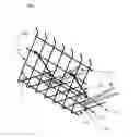
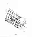
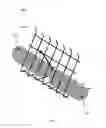
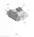
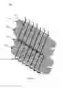
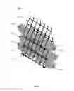
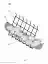
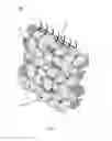
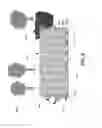
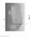
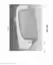
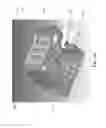
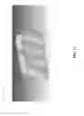

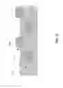
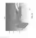
Sources:
- United States Patent and Trademark Office - verify current appl. status at the USPTO↗
Recent applications in this class:
- » 20230295894 2023-09-21
RETAINING WALL STRUCTURE - » 20190234042 2019-08-01
Bag For Shoring Bank Of Body of Water - » 20170298589 2017-10-19
Compressed netting sleeve for in situ manufacture of compost filter socks and method of forming compost filter socks using same - » 20160017566 2016-01-21
Interconnecting member for a sand or soil bag structure - » 20150047298 2015-02-19
METHOD OF FORMING A VACUUM PACKED COMPRESSED NETTING SLEEVE FOR IN SITU MANUFACTURE OF COMPOST FILTER SOCKS AND METHOD OF FORMING COMPOST FILTER SOCKS USING SAME - » 20140270960 2014-09-18
Device for coastal restoration - » 20140050537 2014-02-20
Bag for retaining wall - » 20120195695 2012-08-02
Bag for retaining wall - » 20110110728 2011-05-12
METHOD FOR CONSTRUCTING AN ENVIRONMENTALLY-FRIENDLY RETAINING WALL USING SOIL BAGS FOR VEGETATION AND FIXING MEMBERS, AND INSTALLATION STRUCTURE THEREOF - » 20110103900 2011-05-05
Bag for retaining wall