Lens module
US20170139174A1
2017-05-18
15/082,836
2016-03-28
✅ Patent granted
US 10,114,192 B2
2018-10-30
-
-
Loha Ben
Na Xu | IPro, PLLC
2036-03-28
Abstract:
The present disclosure discloses a lens module. The lens module includes a lens barrel and a lens group. The lens group is installed inside the lens barrel. The lens barrel includes a first barrel wall extended horizontally and a second barrel wall bended and extended from the first barrel wall. The lens module includes also a stop installed inside the lens barrel. The stop is installed inside the lens barrel and clamped between the first barrel wall and the lens group. The stop and the lens group are lined up in turn from object side to image side.
Inventors:
- Jie MA 81 🇨🇳 Shenzhen, China
- Junjie Yan 32 🇨🇳 Shenzhen, China
- Chuandong Wei 78 🇨🇳 Shenzhen, China
- Yuchan Gao 15 🇨🇳 Shenzhen, China
Assignee:
- AAC TECHNOLOGIES PTE. LTD 958 🇸🇬 Singapore, Singapore
- AAC Technologies Pte. Ltd. 343 🇸🇬 Singapore city, Singapore
Applicant:
Interested in similar patents?
Get notified when new applications in this technology area are published.
Classification:
G02B7/026 » CPC main
Mountings, adjusting means, or light-tight connections, for optical elements for lenses using retaining rings or springs
G02B7/003 » CPC further
Mountings, adjusting means, or light-tight connections, for optical elements Alignment of optical elements
G02B7/021 » CPC further
Mountings, adjusting means, or light-tight connections, for optical elements for lenses for more than one lens
G02B9/04 » CPC further
Optical objectives characterised both by the number of the components and their arrangements according to their sign, i.e. + or - having two components only
G02B13/001 » CPC further
Optical objectives specially designed for the purposes specified below Miniaturised objectives for electronic devices, e.g. portable telephones, webcams, PDAs, small digital cameras
G02B13/003 » CPC further
Optical objectives specially designed for the purposes specified below; Miniaturised objectives for electronic devices, e.g. portable telephones, webcams, PDAs, small digital cameras characterised by the lens design having at least one aspherical surface having two lenses
G02B7/02 IPC
Mountings, adjusting means, or light-tight connections, for optical elements for lenses
G02B13/00 IPC
Optical objectives specially designed for the purposes specified below
G02B7/00 IPC
Mountings, adjusting means, or light-tight connections, for optical elements
Description
FIELD OF THE DISCLOSURE
The present disclosure generally relates to the technical field of optical imaging, more particular to a lens module used in camera, video camera, mobile phone, tablet, notebook PC and other electronic devices.
BACKGROUND
As the photographic technology and the electronic products with photographic function are developed in recent years, optical camera lens module is used widely in all kinds of products. In order to follow the current trend that the size of electronic products becomes smaller and smaller, the lens module shall also be miniaturized.
In the existing technology, the lens module comprises a lens barrel, lenses located in the lens barrel, and a stop clamped between lenses. The lens barrel comprises a first barrel wall extended horizontally and a second barrel wall extended from the first barrel wall. A light hole is created on the first barrel wall for the lens. However, the light hole on the first barrel wall requires the barrel wall with a certain thickness, therefore, the wall thickness of the barrel wall is increased. The height and weight of entire lens module is increased. It will be more difficult to produce lens barrel.
For this reason, it is necessary to provide a novel lens module to overcome the shortcomings above.
BRIEF DESCRIPTION OF THE DRAWINGS
Many aspects of the embodiment can be better understood with reference to the following drawings. The components in the drawing are not necessarily drawn to scale, the emphasis instead being placed upon clearly illustrating the principles of the present disclosure. Moreover, in the drawings, like reference numerals designate corresponding parts throughout the several views.
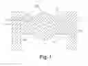
FIG. 1 is a schematic diagram of a lens module in one embodiment of the present disclosure.
DETAILED DESCRIPTION
The present disclosure will be described in detail below with reference to the attached drawings and an exemplary embodiment thereof.
FIG. 1 shows a lens module in one embodiment of the utility model. The lens module comprises a lens barrel 1 and a lens group 2. The lens group 2 is installed inside the lens barrel 1. The lens barrel 1 comprises a first barrel wall 11 extended horizontally and a second barrel wall 12 extended from the first barrel wall 11. The lens module comprises a stop 3 installed inside the lens barrel 1 and clamped between the first barrel wall 11 and the lens group 2. The stop 3 and the lens group 2 are lined up in turn from object side to image side. The stop 3 creates a light hole 4.
The lens group 2 shown in FIG. 1 includes a first lens 21 and a second lens 22. The quantity of the lenses in actual lens group can be changed greatly according to different types and different focal length of lens barrels.
An object side refers to the side of the lens barrel closer to the object. An image side refers to the opposite side of the object side. It can be seen in FIG. 1 that the first barrel wall 11 is closer to object side, and the length of the first barrel wall 11 along the lens barrel center is greater than the second barrel wall 12.
In the lens module in the embodiment, the lens group 2 is provided with the first lens 21. The first lens 21 includes a first optical part 211 and a first bearing part 212 surrounded the first optical part 211. A normal projection of the first optical part 211 along the optical axis is located at least partially on the stop 3.
In the lens module, the first lens 21 is provided with a lug 213 extended from the first bearing part 212 to the first barrel wall 11. The stop 3 is located partially on the lug 213.
In the embodiment, the axis of the lens group 2 and the axis of the light hole 4 are aligned with each other.
The stop 3 is a hollow ring. In this embodiment, the thickness of the stop 3 is 1 mm-5 mm. The main purpose of the stop is to improve the image quality of the lens by reducing the reflective light on the inner wall of the light hole, so that the thickness of the stop cannot exceed the width of the lug molded with the lens barrel along the axial direction of the lens.
The beneficial effects of the lens module of the present disclosure are as follows:
-
- 1. The stop is clamped between the first barrel wall and the lens group. The lens group installed inside the lens barrel presses down the stop on the lug. The stop creates a block structure for installing the lens group and replacing the convex part molded on existing lens barrel. As the thickness of the stop is much smaller than the width of the lug along the axial direction of the lens barrel, the length of the lens barrel is reduced greatly.
- 2. As the thickness of the stop is much smaller than the width of the convex part along the axial direction of the lens barrel, the reflection of the light on the inner surface of the stop is reduced significantly when the light passes though the light hole in the lens group. The glare of imaging is reduced greatly and the image quality of the lens is improved.
- 3. When the lens barrel top has a certain thickness, as the length of the lens barrel is reduced due to the stop, the production difficulty of the lens barrel is reduced and the yield of qualified lens barrel is increased.
It is to be understood, however, that even though numerous characteristics and advantages of the present embodiment have been set forth in the foregoing description, together with details of the structures and functions of the embodiment, the disclosure is illustrative only, and changes may be made in detail, especially in matters of shape, size, and arrangement of parts within the principles of the invention to the full extent indicated by the broad general meaning of the terms in which the appended claims are expressed.
Claims
What is claimed is:1. A lens module comprising:
a lens barrel comprising a first barrel wall extended horizontally and a second barrel wall extended from the first barrel wall;
a lens group installed inside the lens barrel, and comprising a stop installed inside the lens barrel; wherein
the stop is installed inside the lens barrel and clamped between the first barrel wall and the lens group, the stop and the lens group are lined up in turn from an object side to an image side.
2. The lens module according to claim 1, wherein the stop is a hollow ring.
3. The lens module according to claim 2, wherein the lens group is provided with a first lens including a first optical part and a first bearing part surrounded the first optical part, the stop is clamped between the first barrel wall and the first bearing part.
4. The lens module according to claim 3, wherein a normal projection of the first optical part along an optical axis of the lens module is located at least partially on the stop.
5. The lens module according to claim 3, wherein the first lens is provided with a lug extending from the first bearing part to the first barrel wall, the stop is located partially on the lug.
6. The lens module according to claim 1, wherein the stop forms a light hole, and the axis of the lens group and the axis of the light hole are aligned with each other.
Images & Drawings included:
Sources:
- United States Patent and Trademark Office - verify current appl. status at the USPTO↗
Similar patent applications:
- » 20120170125
LENS MODULE, LENS WAFER MODULE, AND METHOD OF MANUFACTURING LENS MODULE - » 20220043233
FIXING RING FOR LENS MODULE, LENS MODULE, AND ELECTRONIC DEVICE - » 20200057240
Lens sealing sleeve, lens module, lens adjustment module, and projection device - » 20240248277
LENS MODULE AND CAMERA MODULE INCLUDING LENS MODULE - » 20200326499
Lens module and lens module control method - » 20210048562
Liquid lens module, lens assembly including the same, and camera module including the lens assembly - » 20080080847
Lens module and camera module using the lens module - » 20200379240
Prism device applied to periscope lens module and periscope lens module - » 20090279186
Movable lens module and optical lens module - » 20150000126
METHOD OF MAKING LENS MODULES AND THE LENS MODULE
Recent applications in this class:
- » 20250277957 2025-09-04
LENS UNIT - » 20250216644 2025-07-03
LENS UNIT - » 20250164736 2025-05-22
MONOCULAR HANDHELD DEVICE AND OBJECTIVE LENS ASSEMBLY - » 20250155666 2025-05-15
MOBILE PHONE LENS PROTECTION COVER - » 20250138272 2025-05-01
LENS MODULE - » 20250138271 2025-05-01
LENS UNIT - » 20250110309 2025-04-03
LENS DRIVING APPARATUS AND CAMERA MODULE - » 20250060558 2025-02-20
OPTICAL IMAGE CAPTURING LENS - » 20250013001 2025-01-09
LENS UNIT - » 20240369803 2024-11-07
LENS APPARATUS AND IMAGE PICKUP APPARATUS
Recent applications for this Assignee:
- » 20250106561 2025-03-27
MICROELECTROMECHANICAL SYSTEM MEMBRANE - » 20250042724 2025-02-06
CAPACITIVE SENSING CIRCUIT AND CAPACITIVE SENSING METHOD - » 20240284120 2024-08-22
Acoustic transducer and method for manufacturing acoustic transducer - » 20240284119 2024-08-22
Acoustic transducer and method for manufacturing acoustic transducer - » 20240236551 2024-07-11
LOUDSPEAKER ASSEMBLY AND HAND-HELD DEVICE - » 20240236550 2024-07-11
Sound reproducing apparatus and method - » 20240223942 2024-07-04
Speaker module - » 20240223941 2024-07-04
Speaker module - » 20240223937 2024-07-04
Speaker module - » 20240214749 2024-06-27
MEMS OPTICAL MICROPHONE