Method for loose joint detection in medium voltage switchgears and medium voltage switchgear itself
US20170146471A1
2017-05-25
15/353,750
2016-11-17
✅ Patent granted
US 10,741,051 B2
2020-08-11
-
-
Lisa M Caputo | Nasir U. Ahmed
Leydig, Voit & Mayer, Ltd.
2037-10-26
Abstract:
A method for loose joint detection in medium voltage switchgears with busbar joints, circuit breaker upper and lower spouts, and cable connection joints, arranged in an air insulated housing, and medium voltage switchgear itself, in order to create an effective loose joint detection with lower operating expense, but with high performance and accuracy, involves measuring actual temperatures at a first phase as a first temperature (T1), at a second phase as a second temperature (T2), at a third phase as a third temperature (T3), at predefined critical points, such as at the busbar joints, and/or at the circuit breaker upper spouts, and/or at the circuit breaker lower spouts, and/or the cable connection; and comparing temperatures in a logical dependency Ti>(Tj+dT), with i≠j, permuted with i from 1, 2, 3, and j from 1, 2, 3, and setting the alarm if the logical dependency is fulfilled.
Inventors:
- Massimo Scarpellini 7 🇮🇹 Dalmine, Italy
- Marcel Stupak 2 🇨🇿 Brno, Czech Republic
- Tomas Kozel 32 🇨🇿 Brno, Czech Republic
- Stefano Magoni 12 🇮🇹 Osio Sotto, Italy
Assignee:
- ABB SCHWEIZ AG 2,771 🇨🇭 Baden, Switzerland
Applicant:
Interested in similar patents?
Get notified when new applications in this technology area are published.
Classification:
G01R31/3274 » CPC further
Arrangements for testing electric properties; Arrangements for locating electric faults; Arrangements for electrical testing characterised by what is being tested not provided for elsewhere; Testing of circuit interrupters, switches or circuit-breakers of high voltage or medium voltage devices; Apparatus, systems or circuits therefor Details related to measuring, e.g. sensing, displaying or computing; Measuring of variables related to the contact pieces, e.g. wear, position or resistance
G01K13/00 » CPC further
Thermometers specially adapted for specific purposes
G08B21/18 IPC
Alarms responsive to a single specified undesired or abnormal condition and not otherwise provided for Status alarms
G08B21/182 » CPC main
Alarms responsive to a single specified undesired or abnormal condition and not otherwise provided for; Status alarms Level alarms, e.g. alarms responsive to variables exceeding a threshold
H02B1/04 » CPC further
Frameworks, boards, panels, desks, casings; Details of substations or switching arrangements; Boards, panels, desks; Parts thereof or accessories therefor Mounting thereon of switches or of other devices in general, the switch or device having, or being without, casing
G01R31/3275 » CPC further
Arrangements for testing electric properties; Arrangements for locating electric faults; Arrangements for electrical testing characterised by what is being tested not provided for elsewhere; Testing of circuit interrupters, switches or circuit-breakers of high voltage or medium voltage devices Fault detection or status indication
H02B11/12 » CPC further
Switchgear having carriage withdrawable for isolation with isolation by horizontal withdrawal
H02B13/065 » CPC further
Arrangements of switchgear in which switches are enclosed in, or structurally associated with, a casing, e.g. cubicle with metal casing; Gas-insulated switchgear Means for detecting or reacting to mechanical or electrical defects
G01R31/327 IPC
Arrangements for testing electric properties; Arrangements for locating electric faults; Arrangements for electrical testing characterised by what is being tested not provided for elsewhere Testing of circuit interrupters, switches or circuit-breakers
H02B1/06 » CPC further
Frameworks, boards, panels, desks, casings; Details of substations or switching arrangements; Boards, panels, desks; Parts thereof or accessories therefor having associated enclosures, e.g. for preventing access to live parts
H02B13/035 » CPC further
Arrangements of switchgear in which switches are enclosed in, or structurally associated with, a casing, e.g. cubicle with metal casing Gas-insulated switchgear
H02B1/24 » CPC further
Frameworks, boards, panels, desks, casings; Details of substations or switching arrangements Circuit arrangements for boards or switchyards
G01N25/72 » CPC main
Investigating or analyzing materials by the use of thermal means Investigating presence of flaws
H02B13/025 » CPC further
Arrangements of switchgear in which switches are enclosed in, or structurally associated with, a casing, e.g. cubicle with metal casing Safety arrangements, e.g. in case of excessive pressure or fire due to electrical defect
H02B1/20 » CPC further
Frameworks, boards, panels, desks, casings; Details of substations or switching arrangements Bus-bar or other wiring layouts, e.g. in cubicles, in switchyards
Description
CROSS-REFERENCE TO RELATED APPLICATIONS
Priority is claimed to European Patent Application No. 15 195 462.5, filed on Nov. 19, 2015, the entire disclosure of which is hereby incorporated by reference herein.
FIELD
The invention relates to a method for loose joint detection in medium voltage switchgears with busbar joints, circuit breaker upper and lower spouts, and cable connection joints, arranged in an air insulated housing, and medium voltage switchgear itself.
BACKGROUND
Loose joints in aforesaid switchgears produce local heat as a consequence of higher transition resistances of such loose joints. Such faults have to be detected, because in dependency of the resulting higher electrical resistance, the produced heat can rise to destructive level, but in any case it produces energy loss in the electrical network. Current practice of loose joint detection involves complex temperatures and currents measurement collected in one point for the whole switchboard, consisting of certain numbers of switchgear panels. In know switchgears, a complex map of the temperatures and currents within the switchboard is created and hot spots are detected by correlating the currents and temperatures. This is expensive because of many measuring points and centralized processing.
A further disadvantage is, that with a centralized system, it is impossible to detect a loose joint in one panel without the measurement from other switchgear panels, and it results in a complex data collection and processing.
SUMMARY
An aspect of the invention provides a method for loose joint detection in a three phase medium voltage switchgear including busbar joints, circuit breaker upper and lower spouts, and cable connection joints, arranged in an air insulated housing, and several temperature measurement points, the method comprising: measuring actual temperatures are measured at a first phase as a first temperature (T1), at a second phase as a second temperature (T2), at a third phase as a third temperature (T3), at one or more predefined critical points; comparing the temperatures in a logical dependency: Ti>(Tj+dT), with i≠j, permuted with i from 1, 2, 3, and j from 1, 2, 3; and setting an alarm if the above condition is fulfilled.
BRIEF DESCRIPTION OF THE DRAWINGS
The present invention will be described in even greater detail below based on the exemplary figures. The invention is not limited to the exemplary embodiments. All features described and/or illustrated herein can be used alone or combined in different combinations in embodiments of the invention. The features and advantages of various embodiments of the present invention will become apparent by reading the following detailed description with reference to the attached drawings which illustrate the following:
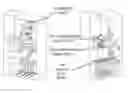
FIG. 1 a logical connection with all needed apparatus; and
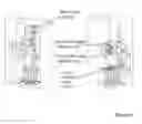
FIG. 2 a perspective view of a switchgear.
DETAILED DESCRIPTION
So it an aspect of the invention, to overcome the disadvantages discussed in the Background by creating an effective loose joint detection with lower operating expense, but with high performance and accuracy.
An aspect of the invention is, that the actual temperatures at the busbar joints (T1), at the circuit breaker upper and lower spouts (T2), and at the cable connection joints (T3) are measured with at least one temperature sensor per phase each, and that the concerning temperature are compared in the following logical dependency,
Ti>(Tj+dT), with I≠j
-
- permutated with i from 1, 2, 3
- and j from 1, 2, 3
and alarm is set if the aforesaid condition is fulfilled.
By this, the loose contacts can be located very quick and easy.
In a further and advantageous embodiment, the method is embellished in such, that alarm is set, if
-
- loose joint in L1 is indicated if T1>(T2+ΔT) or T1>(T3+ΔT)
and/or - loose joint in L2 is indicated if T2>(T1+ΔT) or T2>(T3+ΔT),
and/or - loose joint in L3 is indicated if T3>(T1+ΔT) or T3>(T2+ΔT).
- loose joint in L1 is indicated if T1>(T2+ΔT) or T1>(T3+ΔT)
In a further advantageous embodiment, the value range for ΔT is predefined and stored in a control device, and that all temperatures are read into the control device, in which the evaluation after the rule of claim 1 or claim 2 is proceeded, and which an alarm signal is generated.
In order to have further diagnostic informations, a further embodiment is, that all measured temperature values are stored in a datafile, to enable also retroperspective analysis of historical data.
For that, the datafile is automatically steared and organized as a shift register with an adjustable time frame or time slot.
In order to adapt the system in a kind of self learning strategy, a further advantageous embodiment is, that the time slot is also event triggered, and/or that the retrospective time slot is also event triggered.
According to a medium voltage switchgear with loose joint detection means at busbar joints, circuit breaker upper and lower spouts, and cable connection joints, arranged in an air insulated housing, to proceed the method according to one of the method claims, the invention is, that temperature sensors are arranged at the following joint points of the switchgear, at the busbar joints, at the circuit breaker upper spouts, at the circuit breaker lower spouts, at the cable connection joints, and that such temperature sensors are arranged at all three phases of the aforesaid joints and spouts each, and that a central evaluation unit feed with all the aforesaid temperature sensors values is provided, in order to calculate the aforesaid conditions, mentioned in the claims 1 to 7.
FIG. 1 shows the distributive arrangement of temperature sensors and their a logical connection to a central evaluation unit. Each phase at each joint points are provided with a temperature sensor.
The loose joint detection algorithm proposed in this invention uses following assumptions:
-
- Three phase system (phases marked L1, L2, L3);
- The primary circuit is designed with the same copper cross sections in the three phases in each point; and
- Balanced load (i.e. the currents in the three phases are approximately equal in each point of the primary circuit I1≈I2≈I3).
For the algorithm it is need to further divide the temperature measurements within one panel to groups of three temperature readings. The group always contain reading from L1, L2 and L3 from joints with the same position in the overall system:
-
- Group 1—busbar joints L1, L2, L3;
- Group 2—upper CB spouts L1, L2, L3;
- Group 3—lower CB spouts L1, L2, L3; and
- Group 4—cable connection joints L1, L2, L3,
wherein group 4 is a further grouped area of temperature relevance.
Temperatures are measured on each joint in the group. The measurements do not have to be real time, sufficient reading period is once in one minute, however all three temperatures should be read in short interval of max. 5 seconds:
-
- Joint L1—temperature T1;
- Joint L2—temperature T2; and
- Joint L3—temperature T3.
It is set a threshold of ΔT for giving alarm of loose joint (the threshold value depends on the temperature measurement accuracy and the unbalance expected in the system).
The loose joint detection algorithm is then as follows:
-
- Set alarm loose joint in L1 if T1>(T2+ΔT) or T1>(T3+ΔT);
- Set alarm loose joint in L2 if T2>(T1+ΔT) or T2>(T3+ΔT); and
- Set alarm loose joint in L3 if T3>(T1+ΔT) or T3>(T2+ΔT).
Alternatively the algorithm might be as follows:
-
- Set alarm loose joint in L1 if T1>(T2+ΔT) and T1>(T3+ΔT);
- Set alarm loose joint in L2 if T2>(T1+ΔT) and T2>(T3+ΔT); and
- Set alarm loose joint in L3 if T3>(T1+ΔT) and T3>(T2+ΔT).
The temperature values at the aforesaid joints are measured in the aforesaid groups. The groups 1 to 4 correspond with the central data collection and processing unit for one switchgear panel. In this unit is implemented the aforesaid algorithm, in order to observe the real temperatures versus temperature limits, and to generate alarm if the aforesaid conditions are fulfilled.
FIG. 2 shows one panel form different side views. The aforesaid temperature sensors are distributed in the three phase arrangement and considered as groups for each phase and each joint.
While the invention has been illustrated and described in detail in the drawings and foregoing description, such illustration and description are to be considered illustrative or exemplary and not restrictive. It will be understood that changes and modifications may be made by those of ordinary skill within the scope of the following claims. In particular, the present invention covers further embodiments with any combination of features from different embodiments described above and below. Additionally, statements made herein characterizing the invention refer to an embodiment of the invention and not necessarily all embodiments.
The terms used in the claims should be construed to have the broadest reasonable interpretation consistent with the foregoing description. For example, the use of the article “a” or “the” in introducing an element should not be interpreted as being exclusive of a plurality of elements. Likewise, the recitation of “or” should be interpreted as being inclusive, such that the recitation of “A or B” is not exclusive of “A and B,” unless it is clear from the context or the foregoing description that only one of A and B is intended. Further, the recitation of “at least one of A, B, and C” should be interpreted as one or more of a group of elements consisting of A, B, and C, and should not be interpreted as requiring at least one of each of the listed elements A, B, and C, regardless of whether A, B, and C are related as categories or otherwise. Moreover, the recitation of “A, B, and/or C” or “at least one of A, B, or C” should be interpreted as including any singular entity from the listed elements, e.g., A, any subset from the listed elements, e.g., A and B, or the entire list of elements A, B, and C.
Claims
1. A method for loose joint detection in a three phase medium voltage switchgear including busbar joints, circuit breaker upper and lower spouts, and cable connection joints, arranged in an air insulated housing, and several temperature measurement points, the method comprising:
measuring actual temperatures are measured at a first phase as a first temperature (T1), at a second phase as a second temperature (T2), at a third phase as a third temperature (T3), at one or more predefined critical points;
comparing the temperatures in a logical dependency:
Ti>(Tj+dT), with i≠j,
permuted with i from 1, 2, 3
and j from 1, 2, 3; and
setting an alarm if the above condition is fulfilled.
2. The method of claim 1, wherein the critical points include a busbar joint, a circuit breaker upper spout, a circuit breaker lower spout, a cable connection, or a combination of two or more of any of these.
3. The method of claim 1, wherein the critical points include a busbar joint.
4. The method of claim 1, wherein the critical points include a circuit breaker upper spout.
5. The method of claim 1, wherein the critical points include a circuit breaker lower spout.
6. The method of claim 1, wherein the critical points include a cable connection,
7. The method of claim 1, wherein the alarm is set, based on an indication condition, if:
a loose joint in the first phase is indicated, wherein T1>(T2+ΔT) or T1>(T3+ΔT);
and/or
a loose joint in the second phase is indicated, wherein T2>(T1+ΔT) or T2>(T3+ΔT);
and/or
a loose joint in the third phase is indicated, wherein T3>(T1+ΔT) or T3>(T2+ΔT).
8. The method of claim 7, wherein the indication condition includes the loose joint in the first phase being indicated, wherein T1>(T2+ΔT).
9. The method of claim 7, wherein the indication condition includes the loose joint in the first phase being indicated, wherein T1>(T3+ΔT).
10. The method of claim 7, wherein the indication condition includes the loose joint in the second phase being indicated, wherein T2>(T1+ΔT).
11. The method of claim 7, wherein the indication condition includes the loose joint in the second phase being indicated, wherein T2>(T3+ΔT).
12. The method of claim 7, wherein the indication condition includes the loose joint in the third phase being indicated, wherein T3>(T1+ΔT).
13. The method of claim 7, wherein the indication condition includes the loose joint in the third phase being indicated, wherein T3>(T2+ΔT).
14. The method of claim 1, further comprising:
predefining a value range for ΔT;
storing the value range in a control device; and
reading all temperatures into the control device, the control device evaluating according to the logical dependency or if a loose joint in the first phase is indicated, wherein T1>(T2+ΔT) or T1>(T3+ΔT), and/or a loose joint in the second phase is indicated, wherein T2>(T1+ΔT) or T2>(T3+ΔT), and/or a loose joint in the third phase is indicated, wherein T3>(T1+ΔT) or T3>(T2+ΔT), thereby generating an alarm signal.
15. The method of claim 1, comprising:
storing all measured temperature values in a datafile, thereby enabling retrospective analysis of historical data.
16. The method of claim 15, further comprising:
automatically stearing and organizing the datafile as a shift register including an adjustable time frame or time slot.
17. The method of claim 16, wherein the time slot is also event triggered.
18. The method of claim 17, wherein a retrospective time slot is also event triggered.
19. A medium voltage switchgear, comprising:
a loose joint detector at one or more busbar joints, circuit breaker upper sprouts, circuit breaker lower spouts, and/or cable connection joints, arranged in an air insulated housing, carrying out the method of claim 1;
temperature sensors arranged at joint points of the switchgear, at the busbar joints, at the circuit breaker upper spouts, at the circuit breaker lower spouts, at the cable connection joints, the temperature sensors being arranged at all three phases of the joint points and spouts each; and
a central evaluation unit feed receiving all temperature sensors values, in order to calculate the logical dependency.
Images & Drawings included:
Sources:
- United States Patent and Trademark Office - verify current appl. status at the USPTO↗
Similar patent applications:
Recent applications in this class:
- » 20250271375 2025-08-28
AIRCRAFT FUEL TANK FASTENER INSPECTION - » 20250271374 2025-08-28
IN-SITU VARIABLE TEMPERATURE BOW METROLOGY - » 20250244272 2025-07-31
METHOD FOR DETECTING SURFACE DEFECT OF THERMAL CUP, SYSTEM THEREOF, DEVICE AND MEDIUM - » 20250189472 2025-06-12
DEVICE FOR DETECTING SWITCH DAMAGE USING TEMPERATURE SENSING AND METHOD OF OPERATING THE SAME - » 20250155394 2025-05-15
DETERIORATION DISCRIMINATING DEVICE AND DETERIORATION DISCRIMINATING METHOD - » 20250146964 2025-05-08
THERMAL IMAGING METHOD FOR CRACK AND HOLE DETECTION IN SEMICONDUCTOR DEVICES - » 20250137954 2025-05-01
System and Method for Inspection of Low Emissivity Surfaces Using a Pulsed Light Emitting Diode Heat Source for Thermal Nondestructive Evaluation - » 20250130188 2025-04-24
IMAGE ACQUISITION APPARATUS, INSPECTION APPARATUS, AND IMAGE ACQUISITION METHOD - » 20250076232 2025-03-06
Inspection Apparatus and Mounting Base - » 20250076231 2025-03-06
MONITORING DEVICE
Recent applications for this Assignee:
- » 20250293491 2025-09-18
Switchgear Tank - » 20250291340 2025-09-18
Generating Control Code for an Industrial Plant - » 20250291337 2025-09-18
System and a Method for Mitigating Data Drift in an Industrial Plant - » 20250291331 2025-09-18
System and Method for Anomaly Remediation in an Industrial Process - » 20250290832 2025-09-18
Fault State Detection Apparatus - » 20250290315 2025-09-18
LAYERED PANEL AND METHOD OF CONSTRUCTION THEREOF - » 20250289662 2025-09-18
Vehicle System and Vehicles Therefore - » 20250285824 2025-09-11
Tripping Mechanism - » 20250284268 2025-09-11
Automatic Control Code Generation for Industrial Assets - » 20250283943 2025-09-11
Method of Synchronization of Sensors, Computer Program Product and Computer-Readable Storage Medium