Motor control device, and method for correcting torque constant in such motor control device
US20170163194A1
2017-06-08
15/325,309
2016-01-26
✅ Patent granted
US 10,270,377 B2
2019-04-23
WO; PCT/JP2016/000363; 20160126
WO; WO2016/121373; 20160804
Jorge L Carrasquillo
McDermott Will & Emery LLP
2036-01-26
Abstract:
A motor control device at least includes a speed control part for controlling a motor rotation speed. The motor control device includes a torque correction means for suppressing variation in torque constant due to individual differences of motors. In addition, the motor control device corrects the torque constant by using a correction torque coefficient calculated based on an unloaded speed when a fixed voltage is applied. Alternatively, the torque constant is corrected using the correction torque coefficient calculated based on the motor applied voltage when the motor speed is fixed.
Inventors:
- Ryuta Sasaki 12 🇯🇵 Osaka, Japan
- Daisuke SONODA 6 🇯🇵 Osaka, Japan
- Yasuyuki YOKOUCHI 9 🇯🇵 Osaka, Japan
- Mitsuhiro SAKAMOTO 8 🇯🇵 Osaka, Japan
Assignee:
- Panasonic Intellectual Property Management Co., Ltd. 13,392 🇯🇵 Osaka, Japan
Applicant:
Interested in similar patents?
Get notified when new applications in this technology area are published.
Classification:
H02P21/0025 » CPC main
Arrangements or methods for the control of electric machines by vector control, e.g. by control of field orientation; Control strategies in general, e.g. linear type, e.g. P, PI, PID, using robust control implementing a off line learning phase to determine and store useful data for on-line control
H02P27/06 » CPC further
Arrangements or methods for the control of AC motors characterised by the kind of supply voltage using variable-frequency supply voltage, e.g. inverter or converter supply voltage using dc to ac converters or inverters
H02P6/08 » CPC further
Arrangements for controlling synchronous motors or other dynamo-electric motors using electronic commutation dependent on the rotor position; Electronic commutators therefor Arrangements for controlling the speed or torque of a single motor
H02P21/00 » CPC further
Arrangements or methods for the control of electric machines by vector control, e.g. by control of field orientation
H02P23/0031 » CPC further
Arrangements or methods for the control of AC motors characterised by a control method other than vector control; Control strategies in general, e.g. linear type, e.g. P, PI, PID, using robust control implementing a off line learning phase to determine and store useful data for on-line control
H02P2205/05 » CPC further
Indexing scheme relating to controlling arrangements characterised by the control loops Torque loop, i.e. comparison of the motor torque with a torque reference
H02P23/00 IPC
Arrangements or methods for the control of AC motors characterised by a control method other than vector control
H02P21/20 » CPC further
Arrangements or methods for the control of electric machines by vector control, e.g. by control of field orientation; Estimation or adaptation of machine parameters, e.g. flux, current or voltage Estimation of torque
Description
TECHNICAL FIELD
The present invention relates to motor control devices for controlling a synchronous motor and methods of calculating a correction torque coefficient in the motor control devices.
BACKGROUND ART
In a speed control of a synchronous motor, a conversion coefficient that expresses a relationship between a torque command and actual torque that is actually output from the motor is generally called a torque constant. In general, the torque constant is a fixed value that does not change with speed or current and configures a speed control system. However, the actual torque constant is not always fixed. The torque constant may not be fixed due to an influence of current flowing in the motor and a current control circuit.
PTL1 discloses a conventional method as a technical measure to cope with it. PTL1 has a means to measure actual output torque relative to the torque command by actually driving the motor, and correct the torque command, PTL1 controls the motor using this corrected torque command, so as to keep a fixed torque constant.
However, the above conventional method can correct the torque constant according to motor specifications, but cannot correct an influence of individual differences, such as variation in motor production and variation in characteristic of electronic components in a drive circuit.
CITATION LIST
Patent Literature
PTL1 Japanese Patent Unexamined Publication No. H11-191990
SUMMARY OF THE INVENTION
A motor control device of the present invention includes a speed control part for controlling a motor rotation speed, and a torque correction means for suppressing variation in torque constant due to individual differences of motors. This eliminates influence of torque variation in individual motors and thus achieves high-precision torque control.
BRIEF DESCRIPTION OF DRAWINGS
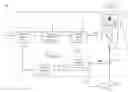
FIG. 1 is a block diagram of a brushless motor equipped with a motor control device in accordance with a first exemplary embodiment of the present invention.
FIG. 2 is an example of structure of a synchronous motor in the brushless motor in accordance with the first exemplary embodiment of the present invention.
FIG. 3 illustrates a relationship between speed and torque of the brushless motor.
FIG. 4A is an example of a configuration of a torque command corrector in the brushless motor in accordance with the first exemplary embodiment of the present invention.
FIG. 4B is an example of another configuration of the torque command corrector in the brushless motor in accordance with the first exemplary embodiment of the present invention.
FIG. 5 is a block diagram of a brushless motor equipped with a motor control device in accordance with a second exemplary embodiment of the present invention.
DESCRIPTION OF EMBODIMENTS
Exemplary embodiments of the present invention are described below with reference to drawings. The exemplary embodiments described herein are illustrative and not restrictive, and the scope of the present invention is not limited thereto.
First Exemplary Embodiment
FIG. 1 is a block diagram of brushless motor 100 equipped with motor control device 10 in the first exemplary embodiment of the present invention.
As shown in. FIG. 1., brushless motor 100 in the exemplary embodiment includes motor control device 10 and synchronous motor 40. Synchronous motor 40, which is a motor in the exemplary embodiment, rotates by applying current and driving synchronous motor 40 with motor control device 10,
In motor control device 10 shown in FIG. 1., rectifying circuit 21 rectifies AC voltage from AC power source 20 to DC voltage. This is then smoothed by smoothing capacitor 22. Then, the DC voltage is supplied to three-phase inverter 23 in motor control device 10. Three-phase inverter 23 converts supplied DV voltage to required AC voltage. A drive voltage of this AC voltage is supplied to synchronous motor 40 including a permanent magnet. In this way, three-phase synchronous motor 40 having U phase, V phase, and W phase shifted by 120 degrees to each other is driven in the exemplary embodiment.
FIG. 2 is an example of a structure of synchronous motor 40 in the exemplary embodiment. As shown in FIG. 2, synchronous motor 40 includes rotor 41 and stator 45. Rotor 41 holds permanent magnet 43 centering on shaft 42. Stator 45 is configured by winding motor coil 40 around stator core 46.
In addition, in the exemplary embodiment, brushless motor 100 has built-in circuit components 48p that function as motor control device 10 in synchronous motor 40. These circuit components 48p are mounted on circuit board 48b. For example, a switching element configuring inverter 23 is mounted on circuit board 48b. Still more, position detector 51 for detecting a rotating position of rotor 41 is disposed facing permanent magnet 43 of rotor 41. In this structure, three-phase AC voltage from inverter 23 is applied to motor coil 47 of each phase to energizing and drive motor coils 47, and rotor 41 rotates while being rotatably supported by bearing 44.
In brushless motor 100 as configured above, motor control device 10 includes current detector 31, torque converter 32, speed operation part 52, speed control part 53, torque command corrector 54, and current control part 55 in the exemplary embodiment shown in FIG. 1, in addition to inverter 23 described above, so as to control the rotation of rotor 41 Still more, motor control device 10 receives rotor position information Pr indicating the rotor position from position detector 51. Furthermore, motor control device 10 receives speed command ω* for controlling the rotation speed typically from an external controller, as a command for controlling the rotation of synchronous motor 40.
Next, in motor control device 10 in FIG. 1, speed operation part 52 calculates a motor speed based on rotor position information Pr detected by position detector 51 typically by differential operation. This is informed to speed control part 53 as detected speed ω. Speed control part 53 calculates and outputs torque command iq* that makes deviation between speed command ω* and detected speed ω zero. In other words, the speed control part calculates torque command iq* based on the deviation between speed command ω* and detected speed a Torque command corrector 54 corrects the torque command by multiplying torque command iq* output from speed control part 53 by correction torque coefficient C(err), and sends corrected torque command iq*(err) obtained to current control part 55. In the exemplary embodiment, torque command corrector 54 is provided to further correct the torque command based on speed deviation, so as to keep a fixed torque constant. In other words, the exemplary embodiment includes this torque command corrector 54 as a torque correction means for making corrections to suppress variation in torque constant due to individual differences of motors.
Current detector 31 detects current flowing when drive voltage Vdr, which is AC drive voltage, is applied to motor coil 47, and outputs it as motor current Idet to torque converter 32. Torque converter 32 performs unit conversion of motor current Idet detected by current detector 31 to torque, and outputs it as detected torque iq to current control part 55. Current control part 55 calculates voltage command Vc such that deviation between torque command iq*(err) after correction and detected torque iq becomes zero, and outputs it to three-phase inverter 23. In other words, current control part 55 generates voltage command Vc for driving motor coils 47 of synchronous motor 40 based on corrected torque command iq*(err) and detected motor current Idet. Then, inverter 23 generates drive voltage Vdr based on voltage command Vc, and generated drive voltage Vdr is applied to motor coil 47.
Next, the structure and operation of aforementioned torque command corrector 54 are further detailed.
As is known by a d-q axis in motor vector control, the d axis is an axis in a magnetic flux direction of permanent magnet 43 of rotor 41 in brushless motor 100, and the q axis is an axis whose phase is advanced for 90 degrees in the rotating direction from the d axis. When current in the d axis is d-axis current id, current in the q axis is q-axis current iq, d-axis inductance of motor coil 47 is Ld, q-axis inductance is Lq, induced voltage constant of synchronous motor is Ke, and the number of pole pairs is Pn; torque T of brushless motor 100 is expressed with Formula 1 below.
Formula 1
T=Pn{Keiq+(Ld−Lq)idiq} (1)
One of the most popular control methods that have been employed in brushless motors is the id=0 control to keep the d-axis current at 0. In this case, a current vector moves on the q axis according to the load state. It is apparent from Formula 1 that reluctance torque Tr=0 when d-axis current id=0. Generated torque thus becomes only magnet torque Tm. In this case, Formula 1 is transformed to Formula 2 below. It is apparent from Formula 2 that the torque is proportional only to q-axis current iq. Accordingly, linear control of torque becomes easy.
Formula 2
Tm=PnKeiq (2)
FIG. 3 shows relationship of speed and torque of brushless motor 100. When applied voltage V is applied to motor coil 47 of brushless motor 100, motor speed ωo in the unloaded state is expressed with Formula 3 below.
Formula 3 ω 0 = V K e ( 3 )
Formula 3 can be transformed to obtain induced voltage constant Ke in Formula 4 below.
Formula 4 K e = V ω 0 ( 4 )
On the other hand, torque Tstd of a reference motor whose induced voltage constant Kstd is already known is expressed with Formula 5 below based on Formula 2.
Formula 5
Tstd=PnKstdiq (5)
When torque Tsmpl and induced voltage constant Ksmpl of a mass-produced motor are assigned to Formula 5, Formula 6 below is obtained.
Formula 6 T std = P n K smpl i q K std K smpl = T smpl K std K smpl ( 6 )
Based on Formula 4, when ωstd is unloaded speed on applying voltage Va to the reference motor, induced voltage constant Kstd is expressed with Formula 7 below.
Formula 7 K std = V a ω std ( 7 )
When ωsmpl is unloaded speed on applying voltage Va to a mass-produced motor under the same conditions, induced voltage constant Ksmpl is expressed with Formula 8 below.
Formula 8 K smpl = V a ω smpl ( 8 )
Following Formula 9 is obtained by assigning Formulae 7 and 8 to Formula 6.
Formula 9 T std = T smpl ω smpl ω std = P n K smpl i q ω smpl ω std ( 9 )
It is apparent from the above that a torque value same as that of the reference motor is obtained by multiplying q-axis current iq by ωsmpl/ωstd in the mass-produced motor. Here, correction torque coefficient C(err) of torque command corrector 54 is this ωsmpl/ωstd, which is a ratio between unloaded speed ωsmpl of the mass-produced motor and unloaded speed ωstd of the reference motor.
FIG. 4A is an example of a configuration of torque command corrector 54 executing the above correction. As shown in FIG. 4A, torque command corrector 54 includes multiplier 54x, and multiplies input torque command iq* by correction torque coefficient C(err)=ωsmpl/ωstd to output a multiplication result as corrected torque command iq*(err).
As described above, torque command corrector 54 is provided as a torque correction means in the exemplary embodiment to correct torque command iq* output from speed controller 53, using correction torque coefficient C(err). This correction of torque command (q-axis current command) eliminates torque variation due to individual differences of motors and enables to keep a fixed torque constant.
More specifically, the maximum speed in the unloaded state is measured in advance by applying a predetermined voltage to a motor coil of the reference motor with known torque constant as a standard motor. Then, the maximum speed in the unloaded state of all motors is measured under the same conditions in a mass production process. Correction torque coefficient C(err) for correcting torque is then calculated based on that speed and the speed of the standard motor, i.e., ωsmpl/ωstd, which is a ratio between unloaded speed ωstd on applying a predetermined voltage to the motor coil of the standard motor in the unloaded state and unloaded speed ωsmpl on applying predetermined voltage to motor coil 47 of synchronous motor 40 in the unloaded state. Torque command iq* is multiplied by correction torque coefficient C(err) to correct the torque constant. This method for correcting torque constant in the exemplary embodiment can improve variation in motor torque. As for specific example, correction torque coefficient C(err) based on the maximum unloaded speed measured in the mass production process may be stored in a storage part, such as a memory, for correction by torque command corrector 54.
The above description refers to a correction method using correction torque coefficient C(err) based on unloaded speed when an applied voltage to the motor coil is fixed to be constant. However, correction torque coefficient Cv(err) based on an applied voltage value when the motor speed is fixed to be constant may be used for correction as the torque correction means.
In this case, correction torque coefficient Cv(err) is calculated as follows.
From Formula 4, induced voltage constant Kstd is expressed with Formula 10 below on applying voltage Vstd to rotate the reference motor at predetermined speed ωa.
Formula 10 K std = V std ω a ( 10 )
On applying voltage Vsmpl to rotate the mass-produced motor at predetermined speed ωa under the same conditions, induced voltage constant Ksmpl is expressed with Formula 11 below
Formula 11 K smpl = V smpl ω a ( 11 )
By assigning Formulae 10 and 11 to Formula 6, Formula 12 below is obtained.
Formula 12 T std = T smpl V std V smpl = P n K smpl i q V std V smpl ( 12 )
As described above, torque variation due to individual differences of motors can be corrected by multiplying torque command (q-axis current command) iq* of the mass-produced motor by correction torque coefficient Cv(err), which is Vstd/Vsmpl. In other words, correction torque coefficient Cv(err) may be Vstd/Vsmpl, which is a ratio between voltage Vstd applied to the motor coil when the reference motor with known torque constant is rotated at a predetermined speed and voltage Vsmpl applied to motor coil 47 when each brushless motor 100 is rotated at the same predetermined speed in the unloaded state,
FIG. 4B shows a configuration of torque command corrector 54 when the above correction is executed. As shown in FIG. 4B, torque command corrector 54 includes multiplier 54x and multiplies input torque command iq* by correction torque coefficient Cv(err)=Vstd/Vsmpl to output a multiplication result as corrected torque command iq*(err).
In the exemplary embodiment, corrected torque command iq*(err), which is corrected torque, is used only in current control part 55. However, it may be used in other controller or arithmetic operation.
Second Exemplary Embodiment
FIG. 5 is a block diagram of brushless motor 101 equipped with motor control device 11 in the second exemplary embodiment of the present invention. Motor control device 11 includes detected torque corrector 33 for correcting detected torque iq in addition to correction of torque command iq*, compared to the first exemplary embodiment in FIG. 1. In FIG. 5, same reference marks are given to components same as those in FIG. 1, and detailed description of these components are omitted.
In FIG. 5, speed operation part 52 calculates a motor speed based on rotor position information Pr detected by position detector 51. This is sent to speed control part 53 as detected speed ω. Speed control part 53 calculates and outputs torque command iq* such that a deviation between speed command ω* and detected speed ω becomes 0.
On the other hand, torque converter 32 performs unit conversion of motor current Idet detected by current detector 31 to torque, and outputs it as detected torque iq. Detected torque corrector 33 corrects detected torque iq, using correction torque coefficient Cd(err), and sends corrected torque iq(err) obtained to current control part 55. In the exemplary embodiment, detected torque corrector 33 is provided to further correct the detected torque based on detected motor current Idet, so as to keep a fixed torque constant.
Current control part 55 calculates voltage command Vc that achieves zero deviation between torque command iq* and corrected torque iq(err), and outputs it to three-phase inverter 23.
Here, with respect to correction by detected torque corrector 33, a torque value same as that of the reference motor is achieved by multiplying detected torque (detected q-axis current) by correction torque coefficient C(err)=ωsmpl/ωstd, as in Formula 9 in the first exemplary embodiment. In the exemplary embodiment, detected torque iq is corrected to eliminate torque variation due to individual differences of motors and keep a fixed torque constant.
In the exemplary embodiment, torque variation due to individual differences of motors can also be corrected by multiplying detected torque (detected q-axis current) by corrected torque coefficient Cdv(err)=Vstd/Vsmpl, as in Formula 12 in the first exemplary embodiment.
INDUSTRIAL APPLICABILITY
As described above, the motor control device of the present invention can solve torque variation due to individual differences of motors, and is thus applicable to general motor control devices having a speed control part (including current minor loop), such as of a servo motor.
REFERENCE MARKS IN THE DRAWINGS
10, 11 Motor control device
20 AC power source
21 Rectifying circuit
22 Smoothing capacitor
23 Inverter
31 Current detector
32 Torque converter
33 Detected torque corrector
40 Synchronous motor
41 Rotor
42 Shaft
43 Permanent magnet
44 Bearing
45 Stator
46 Stator core
47 Motor coil
48b Circuit board
48p Circuit component
51 Position detector
52 Speed operation part
58 Speed control part
54 Torque command corrector
54x Multiplier
55 Current control part
100, 101 Brushless motor
Claims
1. A motor control device at least including a speed control part for controlling a rotation speed of a motor, comprising a torque correction means for making a correction to suppress a variation in a torque constant due to an individual difference of the motor.
2. The motor control device of claim 1, wherein the torque correction means corrects the torque constant based on a maximum unloaded speed when an applied voltage is fixed.
3. The motor control device of claim 1, wherein the torque correction means corrects the torque constant based on a motor applied voltage when a speed of the motor is fixed.
4. The motor control device of claim 2, wherein the torque correction means is used for correcting a torque command output from the speed control part.
5. The motor control device of claim 2, wherein the torque correction means is used for correcting a detected current or a detected torque of the motor.
6. The motor control device of claim 1, comprising:
the speed control part for calculating a torque command based on a deviation between a speed command and a detected speed;
a torque command corrector as the torque correction means for making a correction by multiplying the torque command by a correction torque coefficient and outputting a result of the multiplication as a corrected torque command;
a current control part for generating a voltage command for driving a motor coil of the motor based on the corrected torque command and a detected motor current; and
an inverter for generating a drive voltage for energizing and driving the motor coil based on the voltage command from the current control part.
7. The motor control device of claim 6, wherein the correction torque coefficient is a ratio in an unloaded state between an unloaded speed when a predetermined voltage is applied to a motor coil of a reference motor with a known torque constant and an unloaded speed when the predetermined voltage is applied to the motor coil of the motor.
8. The motor control device of claim 6, wherein the correction torque coefficient is a ratio in an unloaded state between a voltage applied to a motor coil when a reference motor with a known torque constant is rotated at a predetermined speed and a voltage applied to the motor coil when the motor is rotated at the predetermined speed.
9. A method for correcting torque constant in the motor control device of claim 6, comprising:
measuring a maximum unloaded speed of a reference motor with the torque constant already known as a standard motor when a predetermined voltage is applied to a motor coil;
measuring a maximum unloaded speed of all motors in a mass production process under a same condition;
calculating a ratio between an unloaded speed when the predetermined voltage is applied to the motor coil of the reference motor in the unloaded state and an unloaded speed when the predetermined voltage is applied to the motor coil of the motor in the unloaded state, and setting the ratio as the correction torque coefficient; and
making a correction by multiplying the torque command by the correction torque coefficient.
10. The motor control device of claim 3, wherein the torque correction means is used for correcting a torque command output from the speed control part.
11. The motor control device of claim 3, wherein the torque correction means is used for correcting a detected current or a detected torque of the motor.
Images & Drawings included:


Sources:
- United States Patent and Trademark Office - verify current appl. status at the USPTO↗
Similar patent applications:
Recent applications in this class:
- » 20190199257 2019-06-27
Motor control device, and method for correcting torque constant in such motor control device - » 20120217916 2012-08-30
Device and method for generating an initial controller lookup table for an IPM machine
Recent applications for this Assignee:
- » 20250291148 2025-09-18
LENS BARREL AND CAMERA EQUIPPED WITH SAME - » 20250290210 2025-09-18
METHOD FOR CLEAVING DISULFIDE BOND IN PROTEIN AND DEVICE FOR CLEAVING DISULFIDE BOND IN PROTEIN - » 20250289467 2025-09-18
INFORMATION PROCESSING METHOD, COMPUTER PROGRAM PRODUCT, AND INFORMATION PROCESSING APPARATUS - » 20250286901 2025-09-11
DETECTION SYSTEM, DETECTION METHOD, AND RECORDING MEDIUM - » 20250282444 2025-09-11
DRIVE UNIT AND ELECTRIC VEHICLE - » 20250280188 2025-09-04
FILTER MODULE FOR IMAGING APPARATUS - » 20250277834 2025-09-04
INSULATION RESISTANCE DETECTION DEVICE AND INSULATION RESISTANCE DETECTION METHOD - » 20250274653 2025-08-28
ELECTRONIC DEVICE AND SHOOTING MANAGEMENT METHOD - » 20250273929 2025-08-28
LIGHT-EMITTING SYSTEM - » 20250273056 2025-08-28
PORTABLE PAYMENT TERMINAL