Thermal dissipation system of an electric vehicle
US20170166032A1
2017-06-15
15/436,492
2017-02-17
✅ Patent granted
US 9,895,954 B2
2018-02-20
-
-
John D Walters
Kilpatrick Townsend & Stockton LLP
2037-02-17
Abstract:
The present disclosure relates to a thermal dissipation system of an electric vehicle that includes: a heat exchanger arranged at the front part of the electric vehicle for providing heating or cooling to an air conditioning system of the electric vehicle; a first heat sink and a second heat sink, which are respectively arranged at the two sides of the front part of the heat exchanger; a number of rotatable and adjustable air deflectors for changing the flow direction of the air flowing through the heat dissipation system. Temperature sensors are included within the thermal dissipation system for sensing the working temperatures and the environmental temperatures of a battery pack and a motor of the electric vehicle. Opening and closing states of the air deflectors are adjusted in accordance with data provided by the temperature sensors.
Inventors:
- Yong-Syuan Chen 30 🇹🇼 New Taipei City, Taiwan
- Ming-Hui Ho 13 🇹🇼 Tainan City, Taiwan
- Jen-Chieh Hsiao 27 🇹🇼 Taipei City, Taiwan
- Jen-Chieh Hsiao 28 🇹🇼 Taipei, Taiwan
- Yong-Syuan Chen 29 🇹🇼 New Taipei, Taiwan
- Ming-Hui Ho 12 🇹🇼 Tainan, Taiwan
Assignee:
- Thunder Power Hong Kong Ltd. 75 🇭🇰 Central, Hong Kong
- THUNDER POWER NEW ENERGY VEHICLE DEVELOPMENT COMPANY LIMITED 181 🇭🇰 Central, Hong Kong
Applicant:
Interested in similar patents?
Get notified when new applications in this technology area are published.
Classification:
B60H1/00392 » CPC main
Heating, cooling or ventilating [HVAC] devices; Air-conditioning arrangements specially adapted for particular vehicles for vehicles having an electrical drive, e.g. hybrid or fuel cell for electric vehicles having only electric drive means
B60H1/00021 » CPC further
Heating, cooling or ventilating [HVAC] devices; Combined heating, ventilating, or cooling devices Air flow details of HVAC devices
B60H1/00278 » CPC further
Heating, cooling or ventilating [HVAC] devices; HVAC devices specially adapted for particular vehicle parts or components and being connected to the vehicle HVAC unit for the battery
B60H1/143 » CPC main
Heating, cooling or ventilating [HVAC] devices the heat being derived from the propulsion plant otherwise than from cooling liquid of the plant, e.g. heat from the grease oil, the brakes, the transmission unit the heat being derived from cooling an electric component, e.g. electric motors, electric circuits, fuel cells or batteries
H01M10/6566 » CPC further
Secondary cells; Manufacture thereof; Heating or cooling; Temperature control; Means for temperature control structurally associated with the cells characterised by the type of heat-exchange fluid; Gases Means within the gas flow to guide the flow around one or more cells, e.g. manifolds, baffles or other barriers
B60K11/08 IPC
Arrangement in connection with cooling of propulsion units Air inlets for cooling; Shutters or blinds therefor
B60K11/085 » CPC further
Arrangement in connection with cooling of propulsion units; Air inlets for cooling; Shutters or blinds therefor with adjustable shutters or blinds
H01M10/486 » CPC further
Secondary cells; Manufacture thereof; Methods or arrangements for servicing or maintenance of secondary cells or secondary half-cells; Accumulators combined with arrangements for measuring, testing or indicating the condition of cells, e.g. the level or density of the electrolyte for measuring temperature
H01M10/625 » CPC further
Secondary cells; Manufacture thereof; Heating or cooling; Temperature control specially adapted for specific applications Vehicles
H01M10/48 IPC
Secondary cells; Manufacture thereof; Methods or arrangements for servicing or maintenance of secondary cells or secondary half-cells Accumulators combined with arrangements for measuring, testing or indicating the condition of cells, e.g. the level or density of the electrolyte
B60K1/04 » CPC further
Arrangement or mounting of electrical propulsion units of the electric storage means for propulsion
H01M10/663 » CPC further
Secondary cells; Manufacture thereof; Heating or cooling; Temperature control; Heat-exchange relationships between the cells and other systems, e.g. central heating systems or fuel cells the system being an air-conditioner or an engine
B60H2001/003 » CPC further
Heating, cooling or ventilating [HVAC] devices; HVAC devices specially adapted for particular vehicle parts or components and being connected to the vehicle HVAC unit Component temperature regulation using an air flow
B60H2001/00092 » CPC further
Heating, cooling or ventilating [HVAC] devices; Combined heating, ventilating, or cooling devices; Air flow details of HVAC devices; Assembling, manufacturing or layout details of air deflecting or air directing means inside the device
B60K2001/005 » CPC further
Arrangement or mounting of electrical propulsion units with means for cooling the electrical propulsion units the electric storage means
B60H1/00 IPC
Heating, cooling or ventilating [HVAC] devices
B60K11/04 » CPC further
Arrangement in connection with cooling of propulsion units with liquid cooling Arrangement or mounting of radiators, radiator shutters, or radiator blinds
B60H1/14 IPC
Heating, cooling or ventilating [HVAC] devices the heat being derived from the propulsion plant otherwise than from cooling liquid of the plant, e.g. heat from the grease oil, the brakes, the transmission unit
H01M10/613 » CPC further
Secondary cells; Manufacture thereof; Heating or cooling; Temperature control; Types of temperature control Cooling or keeping cold
F16B11/00 » CPC further
Connecting constructional elements or machine parts by sticking or pressing them together, e.g. cold pressure welding
C09J5/00 » CPC further
Adhesive processes in general; Adhesive processes not provided for elsewhere, e.g. relating to primers
G06F3/005 » CPC further
Input arrangements for transferring data to be processed into a form capable of being handled by the computer; Output arrangements for transferring data from processing unit to output unit, e.g. interface arrangements; Specific input/output arrangements not covered by - Input arrangements through a video camera
B60H1/22 IPC
Heating, cooling or ventilating [HVAC] devices the heat being derived otherwise than from the propulsion plant
F16B3/005 » CPC further
Key-type connections; Keys the key being formed by solidification of injected material
H01M10/6563 » CPC further
Secondary cells; Manufacture thereof; Heating or cooling; Temperature control; Means for temperature control structurally associated with the cells characterised by the type of heat-exchange fluid; Gases with forced flow, e.g. by blowers
F25B29/00 » CPC further
Combined heating and refrigeration systems, e.g. operating alternately or simultaneously
H02J7/0019 » CPC further
Circuit arrangements for charging or depolarising batteries or for supplying loads from batteries acting upon several batteries simultaneously or sequentially; Circuits for equalisation of charge between batteries using switched or multiplexed charge circuits
H02J7/0021 » CPC further
Circuit arrangements for charging or depolarising batteries or for supplying loads from batteries acting upon several batteries simultaneously or sequentially Monitoring or indicating circuits
F16B3/00 IPC
Key-type connections; Keys
B60H1/00321 » CPC further
Heating, cooling or ventilating [HVAC] devices Heat exchangers for air-conditioning devices
H01M10/63 » CPC further
Secondary cells; Manufacture thereof; Heating or cooling; Temperature control Control systems
B60K1/00 IPC
Arrangement or mounting of electrical propulsion units
B60K1/00 IPC
Arrangement or mounting of propulsion units in vehicles
G06F3/04842 » CPC further
Input arrangements for transferring data to be processed into a form capable of being handled by the computer; Output arrangements for transferring data from processing unit to output unit, e.g. interface arrangements; Input arrangements or combined input and output arrangements for interaction between user and computer; Interaction techniques based on graphical user interfaces [GUI] for the control of specific functions or operations, e.g. selecting or manipulating an object, an image or a displayed text element, setting a parameter value or selecting a range Selection of displayed objects or displayed text elements
B29C65/002 » CPC further
Joining of preformed parts ; Apparatus therefor Joining methods not otherwise provided for
B32B3/266 » CPC further
Layered products comprising a layer with external or internal discontinuities or unevennesses, or a layer of non-planar form ; Layered products having particular features of form characterised by a particular shape of the outline of the cross-section of a continuous layer; characterised by a layer with cavities or internal voids ; characterised by an apertured layer characterised by an apertured layer, the apertures going through the whole thickness of the layer, e.g. expanded metal, perforated layer, slit layer regular cells
B60L1/02 » CPC further
Supplying electric power to auxiliary equipment of vehicles to electric heating circuits
B32B15/01 » CPC further
Layered products comprising a layer of metal all layers being exclusively metallic
B60H1/00328 » CPC further
Heating, cooling or ventilating [HVAC] devices; Heat exchangers for air-conditioning devices of the liquid-air type
B60H1/00428 » CPC further
Heating, cooling or ventilating [HVAC] devices; Driving arrangements for parts of a vehicle air-conditioning electric
B60H1/00564 » CPC further
Heating, cooling or ventilating [HVAC] devices; Details, e.g. mounting arrangements, desaeration devices; Details of ducts or cables of air ducts
B60H1/00571 » CPC further
Heating, cooling or ventilating [HVAC] devices; Details, e.g. mounting arrangements, desaeration devices; Details of ducts or cables of liquid ducts, e.g. for coolant liquids or refrigerants
B60H1/00885 » CPC further
Heating, cooling or ventilating [HVAC] devices; Control systems or circuits; Control members or indication devices for heating, cooling or ventilating devices; Control systems or circuits characterised by their output, for controlling particular components of the heating, cooling or ventilating installation the components being temperature regulating devices Controlling the flow of heating or cooling liquid, e.g. valves or pumps
B60H1/2215 » CPC further
Heating, cooling or ventilating [HVAC] devices the heat being derived otherwise than from the propulsion plant the heat being derived from electric heaters
G06F3/00 IPC
Input arrangements for transferring data to be processed into a form capable of being handled by the computer; Output arrangements for transferring data from processing unit to output unit, e.g. interface arrangements
G06F3/0482 » CPC further
Input arrangements for transferring data to be processed into a form capable of being handled by the computer; Output arrangements for transferring data from processing unit to output unit, e.g. interface arrangements; Input arrangements or combined input and output arrangements for interaction between user and computer; Interaction techniques based on graphical user interfaces [GUI] based on specific properties of the displayed interaction object or a metaphor-based environment, e.g. interaction with desktop elements like windows or icons, or assisted by a cursor's changing behaviour or appearance Interaction with lists of selectable items, e.g. menus
G06F3/017 » CPC further
Input arrangements for transferring data to be processed into a form capable of being handled by the computer; Output arrangements for transferring data from processing unit to output unit, e.g. interface arrangements; Input arrangements or combined input and output arrangements for interaction between user and computer Gesture based interaction, e.g. based on a set of recognized hand gestures
G06F3/0416 » CPC further
Input arrangements for transferring data to be processed into a form capable of being handled by the computer; Output arrangements for transferring data from processing unit to output unit, e.g. interface arrangements; Input arrangements or combined input and output arrangements for interaction between user and computer; Arrangements for converting the position or the displacement of a member into a coded form; Digitisers, e.g. for touch screens or touch pads, characterised by the transducing means Control or interface arrangements specially adapted for digitisers
G06F3/0484 IPC
Input arrangements for transferring data to be processed into a form capable of being handled by the computer; Output arrangements for transferring data from processing unit to output unit, e.g. interface arrangements; Input arrangements or combined input and output arrangements for interaction between user and computer; Interaction techniques based on graphical user interfaces [GUI] for the control of specific functions or operations, e.g. selecting or manipulating an object, an image or a displayed text element, setting a parameter value or selecting a range
G06F3/04847 » CPC further
Input arrangements for transferring data to be processed into a form capable of being handled by the computer; Output arrangements for transferring data from processing unit to output unit, e.g. interface arrangements; Input arrangements or combined input and output arrangements for interaction between user and computer; Interaction techniques based on graphical user interfaces [GUI] for the control of specific functions or operations, e.g. selecting or manipulating an object, an image or a displayed text element, setting a parameter value or selecting a range Interaction techniques to control parameter settings, e.g. interaction with sliders or dials
H01M10/482 » CPC further
Secondary cells; Manufacture thereof; Methods or arrangements for servicing or maintenance of secondary cells or secondary half-cells; Accumulators combined with arrangements for measuring, testing or indicating the condition of cells, e.g. the level or density of the electrolyte for several batteries or cells simultaneously or sequentially
H01M10/6568 » CPC further
Secondary cells; Manufacture thereof; Heating or cooling; Temperature control; Means for temperature control structurally associated with the cells characterised by the type of heat-exchange fluid; Liquids characterised by flow circuits, e.g. loops, located externally to the cells or cell casings
B32B2605/00 » CPC further
Vehicles
B32B2605/08 » CPC further
Vehicles Cars
B60H2001/00949 » CPC further
Heating, cooling or ventilating [HVAC] devices; Control systems or circuits; Control members or indication devices for heating, cooling or ventilating devices; Control systems or circuits characterised by their output, for controlling particular components of the heating, cooling or ventilating installation the components being temperature regulating devices comprising additional heating/cooling sources, e.g. second evaporator
B60K2001/006 » CPC further
Arrangement or mounting of electrical propulsion units with means for cooling the electrical propulsion units the electric motors
B60R2300/8006 » CPC further
Details of viewing arrangements using cameras and displays, specially adapted for use in a vehicle characterised by the intended use of the viewing arrangement for monitoring and displaying scenes of vehicle interior, e.g. for monitoring passengers or cargo
B60Y2200/91 » CPC further
Type of vehicle; Vehicles comprising electric prime movers Electric vehicles
B60Y2306/07 » CPC further
Other features of vehicle sub-units Heating of passenger cabins
B60Y2400/112 » CPC further
Special features of vehicle units; Electric energy storages Batteries
F16B11/006 » CPC further
Connecting constructional elements or machine parts by sticking or pressing them together, e.g. cold pressure welding by gluing
H01M2220/20 » CPC further
Batteries for particular applications Batteries in motive systems, e.g. vehicle, ship, plane
Y10T428/24347 » CPC further
Stock material or miscellaneous articles; Structurally defined web or sheet [e.g., overall dimension, etc.] including aperture; Composite web or sheet including nonapertured component; Keyed From both sides
H02J7/00 IPC
Circuit arrangements for charging or depolarising batteries or for supplying loads from batteries
B29C65/00 IPC
Joining of preformed parts ; Apparatus therefor
B32B7/04 » CPC further
Layered products characterised by the relation between layers; Layered products characterised by the relative orientation of features between layers, or by the relative values of a measurable parameter between layers, i.e. products comprising layers having different physical, chemical or physicochemical properties; Layered products characterised by the interconnection of layers Interconnection of layers
G06F3/01 IPC
Input arrangements for transferring data to be processed into a form capable of being handled by the computer; Output arrangements for transferring data from processing unit to output unit, e.g. interface arrangements Input arrangements or combined input and output arrangements for interaction between user and computer
G06F3/041 IPC
Input arrangements for transferring data to be processed into a form capable of being handled by the computer; Output arrangements for transferring data from processing unit to output unit, e.g. interface arrangements; Input arrangements or combined input and output arrangements for interaction between user and computer; Arrangements for converting the position or the displacement of a member into a coded form Digitisers, e.g. for touch screens or touch pads, characterised by the transducing means
H01M10/6557 » CPC further
Secondary cells; Manufacture thereof; Heating or cooling; Temperature control; Means for temperature control structurally associated with the cells; Solid structures for heat exchange or heat conduction; Solid parts with flow channel passages or pipes for heat exchange arranged between the cells
F16B5/04 » CPC further
Joining sheets or plates, e.g. panels, to one another or to strips or bars parallel to them by means of riveting
G06F3/0486 » CPC further
Input arrangements for transferring data to be processed into a form capable of being handled by the computer; Output arrangements for transferring data from processing unit to output unit, e.g. interface arrangements; Input arrangements or combined input and output arrangements for interaction between user and computer; Interaction techniques based on graphical user interfaces [GUI] for the control of specific functions or operations, e.g. selecting or manipulating an object, an image or a displayed text element, setting a parameter value or selecting a range Drag-and-drop
B32B3/26 IPC
Layered products comprising a layer with external or internal discontinuities or unevennesses, or a layer of non-planar form ; Layered products having particular features of form characterised by a particular shape of the outline of the cross-section of a continuous layer; characterised by a layer with cavities or internal voids ; characterised by an apertured layer
H01M10/658 » CPC further
Secondary cells; Manufacture thereof; Heating or cooling; Temperature control; Means for temperature control structurally associated with the cells by thermal insulation or shielding
B32B15/00 » CPC further
Layered products comprising a layer of metal
B60R1/00 » CPC further
Optical viewing arrangements; Real-time viewing arrangements for drivers or passengers using optical image capturing systems, e.g. cameras or video systems specially adapted for use in or on vehicles
G06F3/0488 » CPC further
Input arrangements for transferring data to be processed into a form capable of being handled by the computer; Output arrangements for transferring data from processing unit to output unit, e.g. interface arrangements; Input arrangements or combined input and output arrangements for interaction between user and computer; Interaction techniques based on graphical user interfaces [GUI] using specific features provided by the input device, e.g. functions controlled by the rotation of a mouse with dual sensing arrangements, or of the nature of the input device, e.g. tap gestures based on pressure sensed by a digitiser using a touch-screen or digitiser, e.g. input of commands through traced gestures
B32B2605/18 » CPC further
Vehicles Aircraft
G06K9/00 IPC
Methods or arrangements for recognising patterns
Description
CROSS-REFERENCE TO RELATED APPLICATIONS
The present application is a continuation of U.S. Nonprovisional patent application Ser. No. 14/967,373, filed Dec. 14, 2015, which is a continuation of U.S. Nonprovisional patent application Ser. No. 14/842,803, filed Sep. 1, 2015, which claims priority to U.S. Provisional Patent Application No. 62/133,991, filed on Mar. 16, 2015, and U.S. Patent Application No. 62/150,848, filed on Apr. 22, 2015, the disclosures of which are incorporated by reference in their entireties for all purposes.
BACKGROUND
1. Field
The present disclosure relates to thermal dissipation systems for electric vehicles. In particular, a thermal dissipation system configured to recapture heat dissipated from other operational components of the electric vehicle is discussed.
2. Description of Related Art
The present invention relates to an assembly of a heat exchanger used by an air conditioner of an electric vehicle and heat sinks used by a battery and/or a motor. Based on a new design of the electric vehicle, the heat sinks thereof can be arranged on two sides of a portion of the heat exchanger, in order to enable the heat exchanger to take full advantage of waste heat being dissipated by the heat sinks. There is a need to design particular air to enable the heat source from the heat sinks to be absorbed into the heat exchanger, so as to provide optimal heat source management under various conditions.
SUMMARY
To achieve the above purpose, this disclosure describes a thermal dissipation system of an electric vehicle including: a heat exchanger arranged at an air inlet portion of the vehicle for the heat exchange of an air conditioner of the electric vehicle; a first heat sink and second heat sink, which are respectively arranged at the two sides of the front part of the heat exchanger; and a plurality of rotatable and adjustable air deflectors for redirecting air as it flows through the heat exchanger, the first heat sink and the second heat sink.
According to the invention, a number of sensors are arranged for sensing the working temperatures and the environmental temperatures of a battery pack and a motor. Opening and closing states of the air deflectors can be adjusted under different operating states of the air conditioner and different temperatures of the battery pack and the motor, thereby enabling the heat energy dissipated from the first heat sink and the second heat sink to be utilized in an efficient manner
BRIEF DESCRIPTION OF THE DRAWINGS
FIG. 1 is a control module diagram of a heat dissipation system in accordance with an exemplary embodiment of the present disclosure;
FIG. 2A is a schematic diagram of a working mode I of air deflectors in accordance with an exemplary embodiment of the present disclosure;
FIG. 2B is a schematic diagram of a working mode II of the air deflectors in accordance with an exemplary embodiment of the present disclosure;
FIG. 2C is a schematic diagram of a working mode III of the air deflectors in accordance with an exemplary embodiment of the present disclosure;
FIG. 2D is a schematic diagram of a working mode IV of the air deflectors in accordance with an exemplary embodiment of the present disclosure; and
FIG. 3 is a schematic diagram of a control flow of the heat dissipation system in accordance with an exemplary embodiment of the present disclosure.
DETAILED DESCRIPTION
Various embodiments of the present invention will be described below with reference to accompanying drawings constituting a part of the description. It should be understood that, although terms, such as “front”, “rear”, “upper”, “lower”, “left”, “right” and the like, representing directions are used in the present invention for describing various exemplary structural parts and elements of the present invention, these terms are used herein only for the purpose of convenience of explanation and are determined based on the exemplary orientations shown in the accompanying drawings. Since the embodiments disclosed by the present invention can be arranged according to different directions, these terms representing directions are merely used for illustration and should not be regarded as limitation. Wherever possible, the same or similar reference marks used in the present invention refer to the same components.
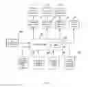
FIG. 1 is a control module diagram of a heat dissipation system in accordance with an exemplary embodiment of the present disclosure.
As shown in FIG. 1, the control system of the heat dissipation system in the present invention at least includes: a controller 101 (provided with a CPU 102 therein), an air conditioner state input 103, a battery pack temperature monitor 104, motor temperature 105, a battery pack environment temperature sensor 110, a motor environment temperature sensor 112, a first air deflector drive 106, a second air deflector drive 107, a third air deflector drive 108, a battery pack heater 109, a first air deflector 111, second air deflectors 121, third deflectors 131 and so on.
The air conditioner state input 103 can be used for inputting the working states of a vehicle cabin air conditioner, which include the following three states: refrigerating, heating and turned off. The air conditioner state input 103 can take many forms including for a multi-position switch allowing a user to manually select one of the states. In some embodiments, the air conditioner state input 103 can take the form of a controller that varies vehicle cabin air conditioner between states to maintain a desired cabin air temperature. The battery pack temperature monitor 104 is arranged in the battery pack for sensing a Tb in the battery pack; the battery pack temperature monitor 104 is made up of multiple temperature sensors 105 arranged at positions having the highest temperatures in the driving parts of the motor, which can include for example a motor drive, a gear box and the like. A motor working temperature Tm is defined as the average value of the highest temperature readings of these parts. The battery pack environment temperature sensor 110 is arranged at the outside of the battery pack for sensing an environment temperature T3 at the outside of battery pack. The motor environment temperature sensor 112 is arranged at the outside of the driving parts of the motor, the motor drive, the gear box and the like for sensing the environment temperature T4 at the outside of the driving parts. All of the temperature sensors mentioned above are connected to the controller 101 and can periodically or continuously the sensed temperatures to the controller 101.
The first air deflector 111, the second air deflectors 121 and the third air deflectors 131 are respectively arranged behind an air inlet portion of the vehicle (specifically as shown in FIG. 2A to FIG. 2D). As an embodiment, the air deflector can be of a louver structure, and the air deflector can be in an open, half-open or closed state by virtue of a rotation of the blades of the louver. In the present invention, the embodiments of the present invention are illustrated just by taking the open and closed states as examples; however, the half-open state of the air deflector is also encompassed in the conception of the present invention and can provide various embodiments in which air flow is even further fine-tuned or adjusted to accomplish a desired cooling or heating configuration. For example, in some embodiments, individual vents or subsets of vents of an air deflector could be turned at different angles to customize a flow of air through the air deflector.
When the vehicle is in operation, air can pass through the opened air deflectors. Each of the air deflectors is provided with a drive, namely the first air deflector drive 106, the second air deflector drive 107 and the third air deflector drive 108. The drives can be electric motors (omitted from the figure) for respectively driving the first air deflector 111, the second air deflectors 121 and the third air deflectors 131. The first air deflector drive 106, the second air deflector drive 107 and the third air deflector drive 108 are also connected to the controller 101. The controller 101 respectively sends a control signal to the above-mentioned drives, and the drives control the opening and closing of the air deflectors when at work.
When the temperature of the battery pack is too low, the controller 101 sends a control signal to the battery pack heater 109, and the battery pack heater 109 works to raise the temperature of the battery pack.
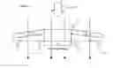
As shown in FIGS. 2A-2D, a first heat sink 220, a heat exchanger 210 and a second heat sink 230 are arranged at the front of the vehicle body or in any portion of the vehicle configured to receive incoming air. The first heat sink 220 and the second heat sink 230 are respectively arranged at two sides of the front part of the heat exchanger 210. The heat exchanger 210 can be a heat exchanger associated with the cabin air conditioner. When the air conditioner is refrigerating, the heat exchanger 210 is configured to dissipate heat, and when the air conditioner is heating, the heat exchanger is configured to absorb heat. When the heat exchanger 210 transitions between heating and cooling configurations, various heating and/or cooling system components can adjust a temperature of cooling/heating elements of the heat exchanger 210. The first heat sink 220 and the second heat sink 230 can be respectively the heat sinks of the motor and the battery pack.
The first air deflector 111, the second air deflectors 121 and the third air deflectors 131 are respectively arranged between two of the first heat sink 220, the heat exchanger 210 and the second heat sink 230. Specifically, the first air deflector 111 is arranged in front of the heat exchanger 210, and the two ends of the first air deflector 111 are respectively connected with the right end of the first heat sink 220 and the left end of the second heat sink 230. In some embodiments, a central portion of the first air deflector 111 can include a protrusion that helps to smoothly split air contacting the central portion of the first air deflector 111 when the first air deflector 111 is closed. The second air deflectors 121 includes two deflectors, a left second air deflector 121.1 and a right second air deflector 121.2, the two ends of the left second air deflector 121.1 are respectively connected with the right end of the first heat sink 220 and the left end of the heat exchanger 210, and the two ends of the right second air deflector 121.2 are respectively connected with the right end of the heat exchanger 210 and the left end of the second heat sink 230; the third air deflectors 131 includes two deflectors, a left third air deflector 131.1 and a right third air deflector 131.2, the left third air deflector 131.1 is arranged behind the first heat sink 220, and the two ends of the left third air deflector are respectively connected with the left end of the first heat sink 220 and the left end of the heat exchanger 210; the right third air deflector 131.2 is arranged behind the second heat sink 230, and the two ends of the right third air deflector are respectively connected with the right end of the second heat sink 230 and the right end of the heat exchanger 210.
When the vehicle is in operation, air 250 enters into the vehicle and when the first air deflector 111 is open (indicated by a dotted line as depicted in FIGS. 2A-2B), the air can through air deflector 111 to flow directly through the heat exchanger 210. When the second air deflectors 121 are closed (indicated by solid lines), the air exiting the first heat sink 220 and the second heat sink 230 cannot flow into the heat exchanger 210. When the third air deflectors 131 are closed and the second air deflectors 121 are open (as depicted in FIG. 2B), the air can flow from the first heat sink 220 and the second heat sink 230 to the heat 210, thereby substantially increasing an average temperature of the air entering the heat exchanger 210.
According to the temperatures of the motor and the battery pack and different states of the cabin air conditioner, the opening and closing of the air deflectors can be adjusted to optimally distribute the heat dissipated by the first heat sink 220 and the second heat sink In some states, at least some of the heat dissipated by the first heat sink 220 and the second sink 230 can be transferred to the heat exchanger 210. The following figures will depict four different working modes that can be assumed by fully opening or closing the air deflectors air deflectors of the thermal dissipation system.
FIG. 2A shows the working mode I of the air deflectors and how the air deflectors affect the incoming air flow.
In mode I, the first air deflector 111 and the third air deflectors 131 are open, the second air deflectors 121 are closed causing the air 250 entering the vehicle to pass through first heat sink 220, the heat exchanger 210 and the second heat sink 230 at the same time. Because the second air deflectors 121 are closed, the portion of air 250 passing through the heat sink 220 and the second heat sink 230 is prevented from passing through the heat exchanger 210. This mode is mainly applicable to the condition that the cabin air conditioner refrigerating. By means of such an arrangement of the air deflectors in this mode, the heat dissipation of the battery pack and the motor has no influence on the refrigeration of the cabin air conditioner while ensuring the heat dissipation effect of the battery pack and the motor.
FIG. 2B shows the working mode II of the air deflectors and how the air deflectors affect the incoming air flow.
In this mode, the first air deflector 111 and the second air deflectors 121 are open, and the third air deflectors 131 are closed. A part of the air 250 passes through the first heat sink 220 and the second heat sink 230 first and then flows through the heat exchanger 210 after being heated by the first heat sink 220 and the second heat sink 230. A portion of the air 250 passes directly through the heat exchanger 210. This mode is mainly applicable to the condition that the cabin air conditioner is turned off and the temperatures of the battery pack and the motor are relatively low. By means of such an arrangement of the air deflectors, a portion of the air 250 passes through the first air deflector 111 to reduce the volume of inlet air passing through the first heat sink 220 and the second heat sink 230. Such a configuration can be beneficial when the battery pack and engine do not require a maximum amount of heat dissipation. This volume of inlet air can ensure the heat dissipation effect of the battery pack and the motor while also allowing an amount of air 250 to engage heat exchanger 210 having been preheated by either of the heat sinks.
FIG. 2C is a schematic diagram of the working mode III of the air deflectors in the present invention.
In this mode, the first air deflector 111 and the second air deflectors 121 are closed, while the third air deflectors 131 are open. In this mode, all the air entering the vehicle only flows through the first heat sink 220 and the second heat sink 230 without passing through heat exchanger 210. This mode is mainly applicable to the condition that the cabin air conditioner is turned off and the temperatures of the battery pack and the motor are relatively high. Under this condition, by closing the first air deflector 111 and the second air deflectors 121 and opening the third air deflectors 131, all the air passes through the first heat sink 220 and the second heat sink 230, so that the volume of the inlet air passing through the first heat sink 220 and the second heat sink 230 is increased compared with the condition that the first deflector is open, and this volume of inlet air can increase the heat dissipation effect on the battery pack and the motor when the battery pack and motor are operating at higher temperatures. Such a configuration can also be advantageous as it reduces any backpressure introduced by the thermal dissipation system associated with directing the air through heat exchanger 210. In this way cooling provided to the battery pack and the engine can be maximized.
FIG. 2D shows the working mode IV of the air deflectors and how the air deflectors affect the incoming air flow.
In this mode, the first air deflector 111 and the third air deflectors 131 are closed, the second air deflectors 121 are open, and all the air entering the vehicle flows through the first heat sink 220 and the second heat sink 230 first and then flows through the heat exchanger 210 after being heated. This mode is mainly applicable to the condition that the cabin air conditioner is heating. Under this condition, by closing the first air deflector in front of the heat exchanger 210, the air firstly flows through the first heat sink 220 and the second heat sink 230 to absorb the heat dissipated from the battery pack and the motor and then transfers some of the absorbed heat to the heat exchanger 210, such that the heat exchanger 210 can effectively utilize the heat dissipated from the battery pack and the motor to provide warm air to the cabin.
FIG. 3 shows one manner in which a controller can be configured to switch between each of the four working modes in accordance with an operating state of the air conditioner and various temperature sensor readings.
FIG. 3 is a schematic diagram of the control flow of the thermal dissipation system in the present invention. The controller 101 executes the steps as shown in FIG. 3. At Step 301, the thermal dissipation system of the electric vehicle is started. Step 302 includes receiving a state signal of the air conditioner inputted via the air conditioner state input 103. At step 303, the following operations are executed in accordance with the state signal of the air conditioner received in step 302.
Heating State:
At step 304, a battery pack temperature Tb is received by a signal transmitted by a battery pack temperature sensor 104.
At step 305: judging whether the battery pack temperature Tb is lower than the lower limit T1 (the first preferable temperature of T1 is 8° C., and the second preferable temperature T1 is 0° C.) of a preferable temperature range of the battery pack according to the temperature signal received in step 304; if yes, executing step 306; if no, executing step 317.
At step 306, sending a control signal to the battery pack heater 109 to drive the battery pack heater 109 to work in order to increase the battery pack temperature Tb, and then repeating step 304.
At step 317, sending a control signal to the first air deflector drive 106, the second air deflector drive 107 and the third air deflector drive 108 to make the air deflectors (111, 121, 131) operate in mode IV.
Turned Off State:
At step 307, receiving a battery pack temperature Tb signal inputted by the battery pack temperature sensor 104.
At step 308 determining whether the battery pack temperature Tb is between the upper limit T2 (the first preferable temperature of T2 is 25° C., the second preferable temperature of T2 is 35° C. and the third preferable temperature of T2 is 45° C.) and the lower limit T1 of the preferable temperature range of the battery pack according to the battery pack temperature signal received in step 307. When Tb≦T1 indicating the battery is operating below the preferable temperature range, executing step 309. When T1<Tb<T2 indicating the battery is operating within the preferable temperature range, executing step 310. When Tb≧T2 indicating the battery is operating above the preferable temperature range executing step 316.
At step 309, sending a control signal to the battery pack heater 109 to drive the battery pack heater 109 to work in order to raise the battery pack temperature Tb up towards T1, and then repeating step 308.
At step 310, receiving a battery pack environment temperature T3 signal inputted by a battery pack environment temperature sensor 110;
At step 311, judging whether the battery pack temperature Tb is higher than the battery pack environment temperature T3 according to the battery pack temperature Tb signal received in step 307 and the battery pack environment temperature T3 signal received in step 310; if yes, executing step 316, if no, executing step 312;
At step 312, receiving a motor working temperature Tm signal and a motor environment temperature T4 signal inputted by the motor temperature sensor 105 and the motor environment temperature sensor 112;
At step 313: judging whether the motor working temperature Tm is higher than the motor environment temperature T4 according to the motor working temperature Tm signal the motor environment temperature T4 signal received in step 312; if yes, executing step 316, no, executing step 315;
At step 315: sending a control signal to the first air deflector drive 106, the second air deflector drive 107 and the third air deflector drive 108 to make the air deflectors (111, 121, 131) be in mode II;
At step 316: sending a control signal to the first air deflector drive 106, the second air deflector drive 107 and the third air deflector drive 108 to make the air deflectors (111, 121, 131) be in mode III; and
Refrigerating State:
At step 314, sending a control signal to the first air deflector drive 106, the second air deflector drive 107 and the third air deflector drive 108 to arrange the air deflectors (111, 121, 131) in accordance with mode I;
The flowcharts of determining different modes of the air deflectors (111, 121, 131) are described above, in order to achieve the comprehensive utilization of energy sources among the first heat sink 220, the second heat sink 230 and the heat exchanger 210 to optimally manage the energy sources.
Although the present invention has been described with reference to the specific embodiments shown in the accompanying drawings, it should be understood that the thermal dissipation system of electric vehicles provided by the present invention can have a variety of variations without departing from the spirit, scope and background of the present invention. Those of ordinary skill in the art should be still aware that, parameters in the embodiments disclosed by the present invention can be changed in different manners, and these changes fall within the spirit and scope of the present invention and the claims.
Claims
What is claimed is:1. A thermal dissipation system suitable for placement within a channel defined by a vehicle that draws ambient air through the channel during operation of the vehicle, the thermal dissipation system comprising:
a heat exchanger configured to provide cooling and heating for an air conditioning system of the vehicle;
a first heat sink and a second heat sink arranged proximately to the heat exchanger, each of the heat sinks being configured to be in thermal contact with a heat emitting component of the vehicle; and
a plurality of air deflectors including a first set of air deflectors configured to alter a flow of the ambient air by transitioning between two configurations of the air deflectors, wherein
in a first configuration, the first set of air deflectors are arranged to direct all the ambient air to one of the first and second heat sinks and rejoin the ambient air after the ambient airflows through the heat exchanger, and
in a second configuration, the first set of air deflectors are arranged to allow a portion of the ambient air to flow directly to the heat exchanger through a gap between the first heat sink and the second heat sink.
2. The thermal dissipation system as recited in claim 1, wherein the first configuration is a heating configuration for the air conditioning system and the second configuration is a cooling configuration for the air conditioning system.
3. The thermal dissipation system as recited in claim 1, wherein the plurality of air deflectors comprises a second set of air deflectors arranged to prevent air flowing through the first and second heat sinks from flowing into the heat exchanger.
4. The thermal dissipation system of claim 3, wherein the plurality of air deflectors further comprises a third set of air deflectors arranged to redirect air exiting the first and second heat sinks into an air intake of the heat exchanger.
5. The thermal dissipation system of claim 4, wherein in the first configuration the first set of deflectors and the second set of deflectors are closed while the first set of deflectors are left open.
6. The thermal dissipation system of claim 4, wherein in the second configuration the first set of deflectors and the third set of deflectors are left open while the second set of deflectors are closed.
7. The thermal dissipation system of claim 1, wherein the heat emitting components of the vehicle are a motor and a battery pack.
8. The thermal dissipation system of claim 7, further comprising:
a controller for adjusting the closing and opening of the plurality of air deflectors in accordance with an operating state of the heat exchanger and the temperatures of the motor and the battery pack.
9. The thermal dissipation system of claim 8, further comprising:
a first temperature sensor disposed within the battery pack; and
a second temperature sensor disposed within the motor,
wherein the first and second temperature sensors periodically send signals to the controller indicating temperature changes in the motor and the battery pack.
10. An electric vehicle, comprising:
a vehicle chassis defining an air inlet;
an air conditioning system configured to govern a temperature within the electric vehicle;
a motor;
a battery pack configured to provide energy to the motor; and
a thermal dissipation system positioned proximate the air inlet and configured to receive air entering the air inlet, the thermal dissipation system comprising:
a heat exchanger configured to provide cooling and heating for an air conditioning system of the vehicle;
a first heat sink and a second heat sink arranged proximately to the heat exchanger, each of the heat sinks being configured to be in thermal contact with a heat emitting component of the vehicle; and
a plurality of air deflectors configured to alter a flow of the ambient air by transitioning between two configurations of the air deflectors, and
a controller configured to direct configuration changes of the plurality of air deflectors, wherein
in a first configuration, the first set of air deflectors are arranged to direct all the ambient air to one of the first and second heat sinks and rejoin the ambient air after the ambient airflows through the heat exchanger, and
in a second configuration, the first set of air deflectors are arranged to allow a portion of the ambient air to flow directly to the heat exchanger through a gap between the first heat sink and the second heat sink.
11. The electric vehicle of claim 10, further comprising:
a battery pack heater in communication with the controller and configured to supply heating to the battery pack when the thermal dissipation system is in a heating mode.
12. The electric vehicle of claim 10, further comprising:
a battery pack temperature sensor arranged in the battery pack and connected to the controller for sensing a working temperature of the battery pack and sending a temperature signal to the controller;
a motor temperature sensor arranged in the motor and connected to the controller for sensing a working temperature of the motor and sending a temperature signal to the controller;
an air conditioner state input connected to the controller for sending a working state of the air conditioner to the controller;
a battery pack environment temperature sensor arranged at the outside of the battery pack and connected to the controller for sensing the environment temperature of the battery pack and sending a temperature signal to the controller; and
a motor environment temperature sensor arranged at the outside of the motor and connected to the controller for sensing the environment temperature of the motor and sending a temperature signal to the controller.
13. The electric vehicle of claim 10, further comprising:
a first air deflector drive, a second air deflector drive and a third air deflector drive, which are used for receiving the control signals of the controller and respectively controlling the opening and closing of a first air deflector, a second air deflector and a third air deflector of the plurality of air deflectors.
14. The electric vehicle of claim 13, wherein the operating modes of the air deflectors comprise at least four modes:
mode I: the first air deflector and the third air deflector are open, the second air deflector are closed, and the air passes through the first heat sink, the heat exchanger and the second heat sink at the same time;
mode II: the first air deflector and the second air deflector are open, the third air deflector is closed, part of the air first passes through the first heat sink and the second heat sink and then flows through the heat exchanger after being heated, and part of the air directly passes through the heat exchanger;
mode III: the first air deflector and the second air deflector are closed, the third air deflector is open, the air only flows through the first heat sink and the second heat sink without passing through the heat exchanger;
mode IV: the first air deflector and the third air deflector are closed, the second air deflectors is open, and the air firstly flows through the first heat sink and the second heat sink and then flows through the heat exchanger after being heated.
15. A thermal dissipation system suitable for use within a vehicle, the thermal dissipation system comprising:
a heat exchanger;
a first heat sink and a second heat sink arranged proximately to the heat exchanger;
a plurality of sensors configured to determine temperatures associated with operational components of the vehicle;
a plurality of air deflectors including a first set of air deflectors configured to alter a flow of the ambient air by transitioning between two configurations of the air deflectors; and
a controller configured to direct a configuration of the plurality of air deflects to be changed in accordance with signals received from the plurality of sensors, the configuration change altering a flow of air through the thermal dissipation system, wherein
in a first configuration, the first set of air deflectors are arranged to direct all the ambient air to one of the first and second heat sinks and rejoin the ambient air after the ambient airflows through the heat exchanger, and
in a second configuration, the first set of air deflectors are arranged to allow a portion of the ambient air to flow directly to the heat exchanger through a gap between the first heat sink and the second heat sink.
16. The thermal dissipation system of claim 15, wherein in a second configuration the air deflectors are arranged to allow a portion of the ambient air to flow directly to the heat exchanger through a gap between the first heat sink and the second heat sink.
17. The thermal dissipation system of claim 15, wherein the first heat sink is configured to be in thermal contact with a motor of the vehicle and the second heat sink is configured to be in thermal contact with a battery of the vehicle.
18. The thermal dissipation system of claim 15, wherein the heat exchanger is associated with an air temperature system of the vehicle.
Images & Drawings included:


Sources:
- United States Patent and Trademark Office - verify current appl. status at the USPTO↗
Similar patent applications:
- » 20160272036
Thermal dissipation system of an electric vehicle - » 20160272045
Thermal dissipation system of an electric vehicle - » 20170113509
Thermal dissipation system of an electric vehicle - » 20180126818
Thermal dissipation system of an electric vehicle
Recent applications in this class:
- » 20250236157 2025-07-24
THERMAL MANAGEMENT SYSTEM AND VEHICLE - » 20250196582 2025-06-19
COMPUTER SYSTEM AND METHOD FOR HEAT GENERATION - » 20250153542 2025-05-15
VEHICLE THERMAL MANAGEMENT SYSTEM - » 20250144975 2025-05-08
THERMAL MANAGEMENT SYSTEM FOR A VEHICLE - » 20240375484 2024-11-14
INTEGRATED THERMAL MANAGEMENT SYSTEM - » 20240367485 2024-11-07
THERMAL MANAGEMENT SYSTEMS AND METHODS FOR RECREATIONAL VEHICLES - » 20240294053 2024-09-05
VEHICLE AIR CONDITIONING SYSTEM AND VEHICLE AIR CONDITIONING METHOD - » 20230373271 2023-11-23
Heat management system - » 20230173887 2023-06-08
Heat pump system for vehicle - » 20230102528 2023-03-30
VEHICLE ENERGY MANAGEMENT SYSTEM, VEHICLE COMPRISING SUCH VEHICLE ENERGY MANAGEMENT SYSTEM, AND METHOD OF CONTROLLING VEHICLE ENERGY MANAGEMENT SYSTEM
Recent applications for this Assignee:
- » 20200395791 2020-12-17
LASER WIRELESS PATH SEGMENTATION CHARGING SYSTEM - » 20190355349 2019-11-21
Voice control system with dialect recognition - » 20190351786 2019-11-21
SEAT RAIL - » 20190315306 2019-10-17
PEDESTRIAN AND VEHICLE PROTECTION SYSTEM - » 20190225200 2019-07-25
Vehicle hazard detection and warning system - » 20190102048 2019-04-04
Interchangeable display of information panels on a dashboard - » 20180331346 2018-11-15
Integrated busbar and battery connection for electric vehicle battery packs - » 20180323409 2018-11-08
Offset vehicle crash elements - » 20180304854 2018-10-25
PLATFORM FOR WIRELESS INTERACTION WITH VEHICLE - » 20180277817 2018-09-27
Battery system assembly press