Auto release safety spear for preassurized beverage containers
US20170190557A1
2017-07-06
15/370,340
2016-12-06
Abstract:
The invention relates to a modified valve apparatus that resides on/in a pressurized vessel/container in which automatically releases pressure upon removal using a specialized tool, thus reducing the possibility for bodily/property damage as well as allowing access into the vessel/container.
Interested in similar patents?
Get notified when new applications in this technology area are published.
Classification:
B67D1/0809 » CPC main
Apparatus or devices for dispensing beverages on draught; Details of beverage containers, e.g. casks, kegs Opening means, e.g. means for assisting the opening
B67D2001/0822 » CPC further
Apparatus or devices for dispensing beverages on draught; Details of beverage containers, e.g. casks, kegs Pressurised rigid containers, e.g. kegs, figals
F16L15/006 » CPC further
Screw-threaded joints ; Forms of screw-threads for such joints with straight threads
B67D1/08 IPC
Apparatus or devices for dispensing beverages on draught Details
B25B13/50 » CPC further
Spanners; Wrenches for special purposes for operating on work of special profile, e.g. pipes
B25B27/24 » CPC further
Hand tools, specially adapted for fitting together or separating parts or objects whether or not involving some deformation, not otherwise provided for for assembling objects other than by press fit or detaching same mounting or demounting valves
Description
BACKGROUND OF THE INVENTION
Field of the Invention
The invention relates generally to an automated pressure relief system for the safe removal of threaded tube/coupler systems in/on the pressurized beverage containers. More specifically, the invention relates to a modified beverage expulsion/valve apparatus that will automatically release any interior pressure upon the removal of the apparatus with a specific tool—which reduces the possibility of premature ejection of the said apparatus and thus bodily harm.
Description of the Related Art
It is perilous and difficult to remove any threaded ‘stopper device’ and/or valve from a pressurized container. If the person attempts to remove a threaded device and/or valve while the contents of the container is under pressure the device and/or valve may (and can) eject out of the container in which it resides and can cause bodily harm as well as property destruction. This is especially problematic with containers classified as ‘kegs’ which can hold all types of liquids and other material.
This problem exists because the current available apparatus/valve systems do not allow for a fail-safe system for removing the apparatus/valve to gain access to the inside of the container.
SUMMARY OF THE INVENTION AND ADVANTAGES
The subject invention comprises a method and apparatus for automatically releasing any interior pressure of a container upon the removal of the apparatus while allowing for normal apparatus operation.
Using a specific tool, the user can remove the threaded valve apparatus from the container and if there is any pressure inside the vessel/container the threaded valve apparatus will release an audible sound (which is caused by the release of pressure).
The release of the pressure allows for the safe removal of the threaded valve apparatus and gain access to the interior of the pressurized container.
BRIEF DESCRIPTION OF THE DRAWINGS
These and other features and advantages of the present invention will become more readily appreciated as the same becomes better understood by reference to the following detailed description when considered in connection with the accompanying drawings wherein:
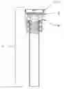
FIG. 1 is a cross-section perspective view showing the valve apparatus that is in common use and is of standard form (free of any vessel/container) with the pressure relief ports.
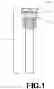
FIG. 2 is a cross-section perspective view representing the valve apparatus that is in common use and is of standard form in which is inserted (threaded) into a vessel/container (including pressure relief ports) to represent the apparatus in use.
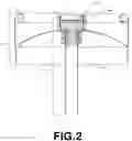
FIG. 3 is a drawing representing the specialized tool used to remove the valve apparatus and how it fits onto a standard socket wrench.
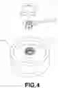
FIG. 4 is a drawing representing an angled, top view, of the specialized tool and a properly installed valve apparatus showing how the end user can remove and insert the valve apparatus using the tool.
DETAILED DESCRIPTION OF THE PREFERRED EMBODIMENT
Referring to the Figures, wherein like numerals indicate like or corresponding parts throughout the several views as follows:
FIG. 1 in this cross-section perspective of the valve apparatus 1 that is threaded 2 and modified with pressure relief ports 3 that automatically releases any pressure once the seal 4 is broken.
FIG. 2 in this cross-section perspective the valve apparatus 1 properly threaded 3 into the vessel/container with the seal 5 properly sealing the pressure relief ports 4.
FIG. 3 represents a standard socket wrench 1 and the tool 2 with keyway tab cutaways 3 combined to form the manner in which the two items are assembled 4.
FIG. 4 shows an elevated side view of a vessel/container 2 with a properly installed valve apparatus 3 and the specialized tool assembly 1 and the motion in which the valve apparatus 3 is inserted (clockwise rotation) and removed (counter-clockwise rotation).
Claims
1. A safety valve apparatus that resides in a pressurized container that automatically relatives any pressure (from inside the vessel/container) when removed using the described tool assembly is substantially shown and described herein.
Images & Drawings included:
Sources:
- United States Patent and Trademark Office - verify current appl. status at the USPTO↗
Recent applications in this class:
- » 20230044330 2023-02-09
Packet opening and discharging device and method of using - » 20160340168 2016-11-24
Apparatus for storing and dispensing liquid from a liquid retaining bag - » 20160060089 2016-03-03
FLUID DISPENSER - » 20140367415 2014-12-18
Method and apparatus for beverage extraction with improved gas cylinder access