Hub member and supporting arms for a pole mounted assembly
US20170191606A1
2017-07-06
15/330,903
2016-11-14
✅ Patent granted
US 10,422,470 B2
2019-09-24
-
-
Alfred J Wujciak
Eric Fincham
2036-11-14
Abstract:
A hub and arm assembly for mounting on a pole, the assembly including a hub having an inner wall and an outer wall with at least one reinforced area formed thereon, the inner wall having a bottom surface, a plurality of transversely extending walls extending between the outer wall and the inner wall with at least one channel being defined therebetween, a supporting member having a vertical segment sized to fit within the channel, and a support arm extending outwardly from the vertical segment, the support arm having a downwardly extending segment designed to abut the reinforced portion of the outer wall.
Applicant:
Interested in similar patents?
Get notified when new applications in this technology area are published.
Classification:
A01G9/12 » CPC further
Cultivation in receptacles, forcing-frames or greenhouses ; Edging for beds, lawn or the like Supports for plants; Trellis for strawberries or the like
E04H12/22 IPC
Towers; Masts or poles; Chimney stacks; Water-towers; Methods of erecting such structures Sockets or holders for poles or posts
A01K39/012 » CPC further
Feeding or drinking appliances for poultry or other birds; Feeding devices, e.g. chainfeeders filling automatically, e.g. by gravity from a reserve
A01K39/014 » CPC further
Feeding or drinking appliances for poultry or other birds; Feeding devices, e.g. chainfeeders Feed troughs; Feed throwers
F16M11/24 » CPC further
Stands or trestles as supports for apparatus or articles placed thereon Stands for scientific apparatus such as gravitational force meters; Undercarriages with or without wheels changeable in height or length of legs, also for transport only, e.g. by means of tubes screwed into each other
E04H12/2223 » CPC further
Towers; Masts or poles; Chimney stacks; Water-towers; Methods of erecting such structures; Sockets or holders for poles or posts not used driven into the ground by screwing
F16M11/041 » CPC further
Stands or trestles as supports for apparatus or articles placed thereon Stands for scientific apparatus such as gravitational force meters; Heads; Means for attachment of apparatus; Means allowing adjustment of the apparatus relatively to the stand Allowing quick release of the apparatus
F16M11/16 » CPC main
Stands or trestles as supports for apparatus or articles placed thereon Stands for scientific apparatus such as gravitational force meters; Heads Details concerning attachment of head-supporting legs, with or without actuation of locking members thereof
F16M2200/066 » CPC further
Details of stands or supports; Arms being part of the head
F16M2200/08 » CPC further
Details of stands or supports Foot or support base
F16M11/04 » CPC further
Stands or trestles as supports for apparatus or articles placed thereon Stands for scientific apparatus such as gravitational force meters; Heads Means for attachment of apparatus; Means allowing adjustment of the apparatus relatively to the stand
A47G7/041 » CPC further
Flower holders or the like; Devices for supporting flower-pots or cut flowers; Flower tables; Stands or hangers, e.g. baskets, for flowers Flower tables or stands
E04H12/2238 » CPC further
Towers; Masts or poles; Chimney stacks; Water-towers; Methods of erecting such structures; Sockets or holders for poles or posts to be placed on the ground
E04H12/347 » CPC further
Towers; Masts or poles; Chimney stacks; Water-towers; Methods of erecting such structures; Arrangements for erecting or lowering towers, masts, poles, chimney stacks, or the like Arrangements for setting poles in the ground
E04H12/24 » CPC further
Towers; Masts or poles; Chimney stacks; Water-towers; Methods of erecting such structures Cross arms
A45B2023/0012 » CPC further
Other umbrellas Ground supported umbrellas or sunshades on a single post, e.g. resting in or on a surface there below
F16M2200/028 » CPC further
Details of stands or supports; Locking means for translational movement by positive interaction, e.g. male-female connections
A47G7/04 IPC
Flower holders or the like; Devices for supporting flower-pots or cut flowers Flower tables; Stands or hangers, e.g. baskets, for flowers
E02D5/801 » CPC further
Bulkheads, piles, or other structural elements specially adapted to foundation engineering; Means for anchoring structural elements or bulkheads; Ground anchors driven by screwing
E04H12/34 IPC
Towers; Masts or poles; Chimney stacks; Water-towers; Methods of erecting such structures Arrangements for erecting or lowering towers, masts, poles, chimney stacks, or the like
F16M11/046 » CPC further
Stands or trestles as supports for apparatus or articles placed thereon Stands for scientific apparatus such as gravitational force meters; Heads; Means for attachment of apparatus; Means allowing adjustment of the apparatus relatively to the stand; Allowing translations adapted to upward-downward translation movement
E02D5/80 IPC
Bulkheads, piles, or other structural elements specially adapted to foundation engineering; Means for anchoring structural elements or bulkheads Ground anchors
A45B23/00 IPC
Other umbrellas
A45F3/44 » CPC further
Travelling or camp articles ; Sacks or packs carried on the body Article supports adapted to be stuck into the ground
A01K39/01 » CPC further
Feeding or drinking appliances for poultry or other birds Feeding devices, e.g. chainfeeders
F16M11/22 » CPC further
Stands or trestles as supports for apparatus or articles placed thereon Stands for scientific apparatus such as gravitational force meters; Undercarriages with or without wheels with approximately constant height, e.g. with constant length of column or of legs
F16M11/08 » CPC further
Stands or trestles as supports for apparatus or articles placed thereon Stands for scientific apparatus such as gravitational force meters; Heads; Means for attachment of apparatus; Means allowing adjustment of the apparatus relatively to the stand allowing pivoting around a vertical axis, e.g. panoramic heads
E04H12/08 » CPC further
Towers; Masts or poles; Chimney stacks; Water-towers; Methods of erecting such structures; Structures made of specified materials of metal
Description
FIELD OF THE INVENTION
The present invention relates to a hub and arm assembly for mounting on a pole.
BACKGROUND OF THE INVENTION
The use of poles for mounting other objects thereon is well established in the prior art. The poles can either be mounted on a stand or alternatively, may be inserted into the soil by applying a rotational force thereto. Typically, the pole will have a screwthread configuration on the bottom portion thereof and the means for applying a rotational force conventionally comprises a transverse bar through which a rotational force may be applied.
Such pole systems suffer from a lack of stability when a transverse force is applied thereto. Typically, such systems will employ a hub or like member to which arms may be attached. The arms in turn are utilized for supporting other objects such as bird feeders, containers, and the like. The use of such systems is limited as they cannot support a substantial weight.
SUMMARY OF THE INVENTION
It is an object of the present invention to provide a hub and arm assembly for mounting on a pole wherein both the hub and the arms are capable of supporting a substantial weight.
According to one aspect of the present invention, there is provided a hub and arm assembly for mounting on a pole comprising a hub having an inner wall and an outer wall, the outer wall having at least one reinforced area formed thereon, the inner wall having a bottom surface, a plurality of transversely extending walls extending between the outer wall and the inner wall, at least one channel being defined by the inner wall, the outer wall and the transverse walls, a supporting member having a vertical segment, the vertical segment being sized to fit within the channel, a support arm extending outwardly from the vertical segment, the support arm having a downwardly extending segment designed to abut the reinforced portion of the outer wall.
The pole used in the embodiments of the present invention may vary. Thus, the pole may be inserted into the soil, usually by means of a screwthreaded lower portion, or alternatively, may utilize a stand or the like.
The hub utilized in the present invention, and as stated above, generally has an inner wall and an outer wall with a plurality of transversely extending walls extending between the outer wall and the inner wall to thereby define one or more channels between the inner wall, outer wall and transverse walls. The channels can be of varying sizes and the use of projections formed on the transversely extending walls may further reduce the size of the channel if so desired.
Adjacent the channel designed to receive the supporting member is a reinforced area. The reinforced area is formed on the outer wall and is designed to abut the supporting member to provide support therefore.
Generally, the reinforced area will comprise a projection formed on the outer wall to substantially increase the thickness thereof at the point where the supporting member abuts the outer wall. This arrangement permits the formation of a hub which can be aesthetically pleasing and does not require the use of vast amounts of material.
The supporting member, as above mentioned, has a vertical segment which is designed to fit within the channel. A support arm extends outwardly from the vertical segment and has a downwardly extending segment designed to abut the reinforced areas of the outer wall. The supporting member may be formed of any suitable material, but preferably is formed of a metallic or plastic material.
Preferably, the outer wall has a slot formed therein adjacent where the channels are located in order to receive the support arm.
BRIEF DESCRIPTION OF THE DRAWINGS
Having thus generally described the invention, reference will be made to the accompanying drawings illustrating an embodiment thereof, in which:
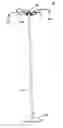
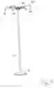
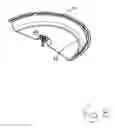
FIG. 1 is a perspective view of a pole mounted hub member with supporting arms;
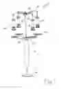
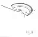
FIG. 2 is a perspective view of a further embodiment thereof;
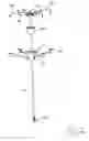
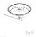
FIG. 3 is a perspective view of the pole and supporting arms;
FIG. 4 is a cross-sectional view of the hub member and arms of FIG. 3;
FIG. 5 is an enlarged perspective view of the upper end of the pole assembly;
FIG. 6 is a cross-sectional view of the hub and arms of FIG. 5;
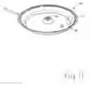
FIG. 7 is an enlarged perspective view of the trays of FIG. 1;
FIG. 8 is cross-sectional view of the tray of FIG. 7;
FIG. 9 is a further cross-sectional view thereof;
FIG. 10 is an exploded view thereof; and
FIG. 11 is a perspective view of the tray in a locked position.
DETAILED DESCRIPTION OF THE INVENTION
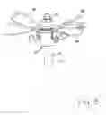
Referring to the drawings in greater detail and by reference characters thereto, there is illustrated in FIG. 1 one embodiment of a pole mounted bird feeding system. This system is generally designated by reference numeral 10.
System 10 includes a central pole 12. Pole 12 may be formed of several sections suitably secured together as may be seen in FIGS. 2 and 3. Surrounding a lower part of pole 12 is a baffle 14 to prevent access to the pole by marauders such as squirrels and raccoons. Pole 12 is also provided with a series of apertures 16 for reasons which will become apparent hereinbelow.
In the embodiment of FIG. 2, pole 12 is provided with a screwthreaded end generally designated by reference numeral 18. Screwthreaded end 18 is conveniently of the type shown in co-pending application Ser. No. 15/330,615 entitled Screwthreaded Pole filed Oct. 19, 2016 in the name of Inventor Paul L. Cote, the teachings thereof are hereby incorporated by reference.
Mounted on pole 12 is an upper hub 22 and a lower hub 24. A plurality of arms 28 extend outwardly from upper hub 22 and each arm carries a bird feeder generally designated by reference numeral 26. Bird feeders 26 may be any suitable; a preferred type of bird feeder is that shown in U.S. Pat. No. 7,191,731 having common inventorship with instant application.
Extending outwardly from lower hub 24 are a plurality of arms 32 each of which support a tray 30. The arrangement is such that there is provided a tray 30 for each bird feeder 26 with the respective tray being located below the bird feeder. This arrangement is advantageous in that many birds when feeding at bird feeder 26 will pick and discard many seeds before they elect to eat one. These discarded seeds would normally be a nuisance as they must be picked up. The discarded seeds also tend to kill vegetation around the bird feeder.
At the top of pole 12 there is provided a finial 34. As shown in the embodiment of FIG. 2, the system may also include containers for plants or the like. In the arrangement shown in FIG. 2, there is provided a central container 38 which is mounted on pole 12. A further container 40 is located therebelow while the arrangement is such that arms 32 support a plurality of smaller containers 42. This provides the user with many options as to how the containers may be used such as utilizing plants which are known to be attractive to birds.
Arms 28, as may be seen in FIG. 2, have a hook 44 formed at the outer most end thereof for hanging bird feeders 26.
As an alternative to the screwthreaded end, a base member 46 may be utilized as shown in FIGS. 1 and 3. Base member 46 will be of a suitable dimension to securely mount pole 12.
Each arm 28 has a downwardly extending segment 48 for reasons which will become apparent hereinbelow.
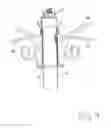
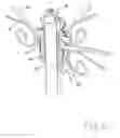
As may be most clearly seen in FIG. 4, upper hub 22 is maintained in position on pole 12 by means of a pin 50 which extends to one of the apertures 16. Pin 50 is utilized to support upper hub 22 and is preferably provided with a structure as shown in co-pending application entitled Pole and Hub filed Nov. 11, 2016 in the name of Inventor Paul L. Cote, the teachings of which are hereby incorporated by reference.
Hub 22 includes an outer wall 54 and an inner wall 56. A plurality of transversely extending walls 58 extend between inner wall 56 and outer wall 54. The outer wall 54, inner wall 56 and transversely extending walls 58 define channels 60. If desired, a pair of projections 62 extending inwardly from transversely extending walls 58 may be used to define channels 60.
Formed on outer wall 54 adjacent channels 60 are reinforced areas 64. Reinforced areas 64 comprise a thickened area which is provided such that downwardly extending segment 48 may abut thereagainst to thereby support arm 28.
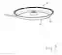
Trays 30, as may be seen in FIGS. 7 to 11, are formed with a central bottom wall 68 with a side wall 70 extending upwardly therefrom. Proximate the point of juncture of bottom wall 68 and side wall 70 are drainage apertures 72 to prevent water to drain therefrom.
Each tray 30 further includes a center structure generally designated by reference numeral 74 and which includes a side wall 76 and a top wall 78. A pair of crisscrossing 80, 82 are formed in top wall 78.
The arrangement is such that a locking structure 84 is provided at the end of each arm 32. Locking structure 84 includes a base 86 and an elongated locking element 88 which is designed to fit within one of slots 80, 82 and the tray is then rotated to lock tray 30 in position as shown in FIG. 11.
Claims
I claim:1. A hub and arm assembly for mounting on a pole comprising:
a hub having an inner wall and an outer wall, said outer wall having at least one reinforced area formed thereon, said inner wall having a bottom surface, a plurality of transversely extending walls extending between said outer wall and said inner wall, at least one channel being defined by said inner wall, said outer wall and said transverse walls;
a supporting member having a vertical segment, said vertical segment being sized to fit within said channel, a support arm extending outwardly from said vertical segment, said support arm having a downwardly extending segment designed to abut said reinforced portion of said outer wall.
2. The hub and arm assembly of claim 1 wherein said reinforced portion formed on said outer wall is located adjacent said at least one channel.
3. The hub and arm assembly of claim 1 wherein said at least one channel is defined by said outer wall, a pair of said transversely extending walls, and first and second projections extending outwardly from said pair of transversely extending walls.
4. The hub and arm assembly of claim 1 wherein said outer wall tapers inwardly from top to bottom.
5. The hub and arm assembly of claim 1 wherein said support arm has a hook shape formed at a free end thereof.
6. The hub and arm assembly of claim 1 wherein said pole has a screwthreaded end for insertion into soil.
7. The hub and arm assembly of claim 1 wherein said pole is mounted on a base stand.
8. The hub and arm assembly of claim 1 wherein said hub is formed of a plastic material.
9. The hub and arm assembly of claim 1 wherein said reinforced area comprises a projection formed on said outer wall.
10. The hub and arm assembly of claim 1 comprising a plurality of supporting members, said hub having a plurality of slots formed therein.
Images & Drawings included:
Sources:
- United States Patent and Trademark Office - verify current appl. status at the USPTO↗
Recent applications in this class:
- » 20250237344 2025-07-24
DUAL CLAMPING DEVICE - » 20250164064 2025-05-22
STAND AND DISPLAY APPARATUS HAVING THE SAME - » 20250102105 2025-03-27
SUPPORTING DEVICE AND DISPLAY APPARATUS INCLUDING THE SAME - » 20250035257 2025-01-30
MULTI-LEGGED EQUIPMENT SUPPORT HAVING LEG ANGLE ADJUSTMENT - » 20240377019 2024-11-14
TRIPOD - » 20240301990 2024-09-12
COMPACT STAND - » 20240288113 2024-08-29
Dual clamping device - » 20240102605 2024-03-28
Multi-legged equipment support having leg angle adjustment - » 20230383896 2023-11-30
Adjustable support apparatuses - » 20230323997 2023-10-12
Adjustable display device assembly