Coupling circuits with capacitors
US20170194931A1
2017-07-06
15/396,801
2017-01-02
✅ Patent granted
US 10,135,417 B2
2018-11-20
-
-
Rakesh Patel
Wei Te Chung | Ming Chieh Chang
2037-01-02
Abstract:
The network filtering circuit includes a cable side for connection with a network cable, a physical side for connection with a mother board, and a plurality of transmission channels connected between the cable side and the physical side. Each of the transmission channels includes a first transmission line and a second transmission line with a CMC linked therebetween. Two filtering (Y type) capacitors are further linked between the first transmission line and the second transmission line with a middle line connected between the two filtering capacitors and having an extension line wherein in such an extension line there are a resistor and an optional adjusting capacitor to a ground node at the end in series connection
Assignee:
- FOXCONN INTERCONNECT TECHNOLOGY LIMITED 922 Grand Cayman, Cayman Islands
Applicant:
Interested in similar patents?
Get notified when new applications in this technology area are published.
Classification:
H03H7/0138 » CPC further
Multiple-port networks comprising only passive electrical elements as network components; Frequency selective two-port networks Electrical filters or coupling circuits
H03H7/1708 » CPC further
Multiple-port networks comprising only passive electrical elements as network components; Frequency selective two-port networks; Structural details of sub-circuits of frequency selective networks Comprising bridging elements, i.e. elements in a series path without own reference to ground and spanning branching nodes of another series path
H03H7/1766 » CPC further
Multiple-port networks comprising only passive electrical elements as network components; Frequency selective two-port networks; Structural details of sub-circuits of frequency selective networks; Comprising typical LC combinations, irrespective of presence and location of additional resistors Parallel LC in series path
H03H7/06 » CPC further
Multiple-port networks comprising only passive electrical elements as network components; Frequency selective two-port networks including resistors
H03H7/427 » CPC main
Multiple-port networks comprising only passive electrical elements as network components; Balance/unbalance networks; Balance-balance networks Common-mode filters
H03H7/482 » CPC further
Multiple-port networks comprising only passive electrical elements as network components; Networks for connecting several sources or loads, working on the same frequency or frequency band, to a common load or source particularly adapted for use in common antenna systems
H03H1/0007 » CPC further
Constructional details of impedance networks whose electrical mode of operation is not specified or applicable to more than one type of network of radio frequency interference filters
H03H7/42 IPC
Multiple-port networks comprising only passive electrical elements as network components Balance/unbalance networks
H03H7/01 IPC
Multiple-port networks comprising only passive electrical elements as network components Frequency selective two-port networks
H03H7/38 » CPC main
Multiple-port networks comprising only passive electrical elements as network components Impedance-matching networks
H03H7/48 IPC
Multiple-port networks comprising only passive electrical elements as network components Networks for connecting several sources or loads, working on the same frequency or frequency band, to a common load or source
H03H1/00 IPC
Constructional details of impedance networks whose electrical mode of operation is not specified or applicable to more than one type of network
Description
BACKGROUND OF THE INVENTION
1. Field of the Invention
The present invention relates to a network filtering circuit, and more particularly to a preferable Electromagnetic Compatibility (EMC) and impedance matching circuit network.
2. Description of Related Arts
Chinese Patent No. CN204733134U issued on Dec. 25, 2013, discloses a network filtering circuit including a cable side, a physical side, and a plurality of differential pair transmission channels connected therebetween. Each of the transmission channels includes a CMC (Common Mode Choke) and two Y type capacitors. Each differential pair transmission channel includes a first transmission line and a second transmission line with the aforementioned two Y type capacitors respectively connected within the first transmission line and the second transmission line in series connection. The CMC includes a first coil and a second coil coupled with each other wherein the CMC is closer to the physical side while the two Y type capacitors are closer to the cable side and directly directed to the ground node. The Electro Magnetic Interference (EMI) is derived from the ground line which performs reference potential, If the ground line is improperly designed, the ground potential will be unstable that have the whole network circuits malfunction. The ground line is used for stabilizing the ground potential, thus eliminating the interference. The prior art shows the Y type capacitor is directly linked to the ground node, thus having the first transmission line and the second transmission line tend to receive the EMI from the ground node and affecting the signal transmission.
SUMMARY OF THE INVENTION
Accordingly, an object of the present invention is to provide network filtering circuit with preferable Electro Magnetic compatibility and impedance matching. The invention includes a cable side for connection with a network cable, a physical side for connection with a mother board, and a plurality of differential pair transmission channels connected between the cable side and the physical side. Each of the transmission channels includes a first transmission line, the second transmission line, two first capacitors linked between the first transmission line and the second transmission line in series connection with a middle line linked to a position of a connection line between these two first capacitors wherein a resistor has one end linked to the middle line and the other end eventually linked to a ground node.
Accordingly, another object of the present invention is to provide network filtering circuit with preferable Electro Magnetic compatibility and impedance matching. The invention includes a cable side for connection with a network cable, a physical side for connection with a mother board, and a plurality of differential pair transmission channels connected between the cable side and the physical side. Each of the transmission channels includes a first transmission line and a second transmission line with a CMC and two coupling capacitors connected thereto in series connection wherein the CMC includes a first coil and a second coil respectively connected to the first transmission line and the second transmission line, the CMC is closer to the physical side while and the two coupling capacitors are closer to the cable side. The network circuit further includes two filtering (Y type) capacitors linked between the first transmission line and the second transmission line, a middle line connected between the two filtering capacitors and having an extension line wherein in such an extension line there are a resistor and an optional adjusting capacitor to a ground node at the end in series connection.
Compared with the prior arts, the invention provides the middle line with an additional resistor before reaching the ground node so as to achieved an efficient grounding effect and the better EMC and corresponding impedance matching.
Other objects, advantages and novel features of the invention will become more apparent from the following detailed description when taken in conjunction with the accompanying drawings.
BRIEF DESCRIPTION OF THE DRAWING
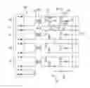
FIG. 1 is a network filtering circuit according to the invention.
DETAILED DESCRIPTION OF THE PREFERRED EMBODIMENT
Reference will now be made in detail to some preferred embodiments of the present invention.
Referring to FIG. 1, a network filtering circuit 100 according to the invention. The network filtering circuit 100 includes a cable side 10 for connection with a network cable, a physical side 30 for connection with a mother board, and a plurality of transmission channels 20 connected between the cable side 10 and the physical side 30.
Each of the transmission channels 60 includes a first (differential) transmission line 201, the second (differential) transmission line 202, and a CMC 40 and two filtering/first capacitors 60 linked, in series connection, between the first transmission line 201 and the second transmission line 202. The CMC 40 includes a first coil 401 and a second coil 402 coupled with each other and respectively connected with the corresponding first transmission line 201 and the second transmission line 202. Two coupling/second capacitors 50 are respectively connected with the corresponding first transmission line 201 and the second transmission line 202 and linked to the corresponding first coil 401 and second coil 402 in series connection. Notably, the CMC is closer to the physical side while the second capacitors 50 are closer to the cable side 10.
A middle line 601 is between the two first capacitors 60 with an extension line (not labeled), and in such an extension line there are a resistor 70 and an adjusting/third capacitor 80 and a ground node 90 at the end in series connection sequentially wherein the resistor 70 is connected between the middle line 601 and the third capacitor 80.
Notably, the second capacitors 50 are located between the CMC and the first capacitors 40. Each of the first transmission line 201 and the second transmission line 202 further includes a fourth capacitor 95 located between the CMC and the corresponding second capacitor 50, and is further directly connected to another ground node 90. Under this arrangement, the first capacitor 60 and the fourth capacitor 95 are respectively linked to two opposite ends of the corresponding second capacitor 50. In this design, the resistor 70 is of 75Ω, the third capacitor 80 is of 1000 pF.
Compared with the prior arts, the invention provides the middle line 601 with an additional resistor 70 and an optional third capacitor 80 before reaching the ground node 90 so as to achieve an efficient grounding effect and the better EMC and corresponding impedance matching.
It is to be understood, however, that even though numerous characteristics and advantages of the present invention have been set forth in the foregoing description, together with details of the structure and function of the invention, the disclosure is illustrative only, and changes may be made in detail, especially in matters of shape, size, and arrangement of parts within the principles of the invention to the full extent indicated by the broad general meaning of the terms in which the appended claims are expressed.
Claims
What is claimed is:1. A network filtering circuit comprising:
a cable side for connection to a network cable;
a physical side for connection to a mother board; and
a plurality of transmission channels connected between the cable side and the physical side, each transmission channel comprising:
a first transmission line and a second transmission line,
a common mode choke having a first coil and a second coil respectively connected to the corresponding first transmission line and second transmission line, respectively;
two first capacitors respectively connected between the corresponding first transmission line and the corresponding second transmission line in series connection, wherein the common mode choke is closer to the physical side while the two first capacitors are closer to the cable side;
a middle line linked between the first two capacitors with an extension line having a distal end connected to a ground node; and
two second capacitors respective connected with the corresponding first transmission line and the corresponding second transmission line; wherein
there is at least a resistor positioned in the extension line for enhancing EMC (Electro Magnetic compatibility).
2. The network filtering circuit as claimed in claim 1, further including a third capacitor linked between the ground node and the first capacitor in the extension line of each transmission channel
3. The network filtering circuit as claimed in claim 2, wherein all transmission channels share the same third capacitor and the same ground node.
4. The network filtering circuit as claimed in claim 2, further including two fourth capacitors respectively connected to the corresponding fist transmission line the corresponding second transmission line in each transmission channel, wherein each fourth capacitor is further linked to another ground node.
5. The network filtering circuit as claimed in claim 4, wherein said fourth capacitors are located between the second capacitors and the common mode choke.
6. The network filtering circuit as claimed in claim 4, wherein in each transmission channel, the two fourth capacitors share the same another ground node.
7. The network filtering circuit as claimed in claim 4, wherein in each of the first transmission line and the second transmission line, the corresponding fourth capacitor and the corresponding first capacitor are respectively linked to two opposite ends of the corresponding second capacitor.
8. The network filtering circuit as claimed in claim 1, wherein said two second capacitors are located between the common mode choke and the two first capacitors.
9. The network filtering circuit as claimed in claim 8, wherein all transmission channels share the same third capacitor and the same ground node.
10. A network filtering circuit comprising:
a cable side for connection to a network cable;
a physical side for connection to a mother board; and
a plurality of transmission channels connected between the cable side and the physical side, each transmission channel comprising:
a first transmission line and a second transmission line,
a common mode choke having a first coil and a second coil respectively connected to the corresponding first transmission line and second transmission line, respectively;
two first capacitors respectively connected between the corresponding first transmission line and the corresponding second transmission line in series connection, wherein the common mode choke is closer to the physical side while the two first capacitors are closer to the cable side;
a middle line linked between the first two capacitors with an extension line having a distal end connected to a ground node; and
two second capacitors respective connected with the corresponding first transmission line and the corresponding second transmission line; wherein
said two second capacitors are located between the common mode choke and the two first capacitors.
11. The network filtering circuit as claimed in claim 10, further including two additional capacitors respectively connected to the corresponding fist transmission line the corresponding second transmission line in each transmission channel, wherein each additional capacitor is further linked to another ground node.
12. The network filtering circuit as claimed in claim 11, wherein said additional capacitors are located between the second capacitors and the common mode choke.
13. The network filtering circuit as claimed in claim 11, wherein in each of the first transmission line and the second transmission line, the corresponding additional capacitor and the corresponding first capacitor are respectively linked to two opposite ends of the corresponding second capacitor.
14. The network filtering circuit as claimed in claim 10, wherein there is at least a resistor positioned in the extension line for enhancing EMC (Electro Magnetic compatibility).
15. The network filtering circuit as claimed in claim 14, further including a third capacitor linked between the ground node and the first capacitor in the extension line of each transmission channel
16. The network filtering circuit as claimed in claim 15, wherein all transmission channels share the same third capacitor and the same ground node.
Images & Drawings included:
Sources:
- United States Patent and Trademark Office - verify current appl. status at the USPTO↗
Similar patent applications:
- » 20050201025
Capacitor coupling circuits - » 20080303703
Cross-coupled switched capacitor circuit with a plurality of branches - » 20190006104
Surface mount multilayer coupling capacitor and circuit board containing the same - » 20200303127
Surface mount multilayer coupling capacitor and circuit board containing the same - » 20140339618
Circuit having capacitor coupled with memory element - » 20050231277
Multistage amplifier circuit without interstage coupling capacitor - » 20150076575
Memory cell array including a write-assist circuit and embedded coupling capacitor and method of forming same - » 20070145528
Power dissipation-optimized high-frequency coupling capacitor and rectifier circuit - » 20090059451
ESD PROTECTION CIRCUIT WITH IMPROVED COUPLING CAPACITOR - » 20080238548
Differential feedback amplifier circuit with cross coupled capacitors
Recent applications in this class:
- » 20250293658 2025-09-18
AFE DEVICES INCLUDING SAMPLER ARRAY AND CLOCK BIAS CIRCUIT - » 20250274094 2025-08-28
RING-BASED MATCHING NETWORKS AND METHODS - » 20250253822 2025-08-07
ELECTRONIC DEVICE - » 20250167751 2025-05-22
MICROWAVE HEAT TREATMENT APPARATUS AND IMPEDANCE MATCHING METHOD - » 20250119113 2025-04-10
SINGLE LADDER DUPLEXER WITH IMPEDANCE GRADIENT - » 20250112611 2025-04-03
DUAL-BAND IMPEDANCE MATCHING CIRCUIT AND METHOD OF IMPEDANCE MATCHING - » 20250105815 2025-03-27
BALUNS WITH INTEGRATED MATCHING NETWORKS - » 20250080077 2025-03-06
PARALLEL-TYPE TX/RX CONCURRENT IMPEDANCE MATCHING UTILIZING RX MUTUAL INDUCTANCE MATCHING - » 20250030394 2025-01-23
ELECTRONIC DEVICE COMPRISING ANTENNA - » 20240421792 2024-12-19
APPARATUSES AND METHODS INVOLVING FREQUENCY-TUNING MATCHING NETWORK
Recent applications for this Assignee:
- » 20240199157 2024-06-20
METHOD OF CONTROLLING STATE OF ELECTRIC ASSIST BICYCLE, CONTROL SYSTEM, AND ELECTRONIC DEVICE - » 20240177887 2024-05-30
CORE WIRE AND METHOD OF MAKING SAME AND CABLE INCLUDING THE CORE WIRE - » 20240072477 2024-02-29
ELECTRICAL CONNECTOR WITH IMPROVED CONTACTS - » 20240055792 2024-02-15
Electrical connector having an angled part and a U-shaped plate together defining a tubular structure - » 20230352880 2023-11-02
ELECTRICAL CONNECTOR WITH IMPROVED INSERTING MEMBER - » 20230335934 2023-10-19
ELECTRICAL CONNECTOR - » 20230307870 2023-09-28
Electrical connector assembly having improved locking elements - » 20230283018 2023-09-07
ELECTRICAL CONNECTOR ASSEMBLY WITH IMPROVED TERMINALS - » 20230268679 2023-08-24
Electrical connector assembly - » 20230238732 2023-07-27
ELECTRICAL CONNECTOR ASSEMBLY HAVING A METAL PLATE FOR MOUNTING A CONNECTOR TO A HOUSING