Ceramic tile fan blade containment
US20170198714A1
2017-07-13
14/991,817
2016-01-08
✅ Patent granted
US 10,125,788 B2
2018-11-13
-
-
Dwayne J White | Adam W Brown
General Electric Company | Brian Overbeck
2037-02-28
Abstract:
Fan blade containment system includes circular tile layer of annular ceramic tiles attached to and extending radially inwardly from a shell, radially inner and outer annular surfaces of ceramic tiles bonded to a radially inner composite layer and the shell respectively with elastomeric inner and outer adhesive layers respectively. Elastomeric adhesive layers between circumferentially adjacent overlapped or scarfed edges along circumferential edges of the ceramic tiles overlap and mate along oppositely facing surfaces of adjacent ones of the ceramic tiles. Inner and outer adhesive layers and elastomeric adhesive layer may be a double-sided adhesive foam tape. Scarfed edges may be bevels or rabbets. Shell may be made of a metal or composite material. Fan blade containment system may be bonded to and extend inwardly from fan case circumscribing fan blades of a fan. Inner composite layer and composite outer shell may be co-cured with ceramic tiles therebetween.
Inventors:
- Benjamin James Roby 5 🇺🇸 Fairfield, OH, United States
- Wendy Wen-Ling Lin 10 🇺🇸 Montgomery, OH, United States
- David Sujay Kingsley 1 🇺🇸 Cincinnati, OH, United States
Assignee:
- GENERAL ELECTRIC COMPANY 28,775 🇺🇸 Schenectady, NY, United States
Applicant:
Interested in similar patents?
Get notified when new applications in this technology area are published.
Classification:
F04D29/526 » CPC main
Details, component parts, or accessories; Casings; Connections of working fluid for axial pumps especially adapted for elastic fluid pumps Details of the casing section radially opposing blade tips
B29C65/4805 » CPC further
Joining of preformed parts ; Apparatus therefor using adhesives, i.e. using supplementary joining material; solvent bonding characterised by the type of adhesives
B29C66/1286 » CPC further
General aspects of processes or apparatus for joining preformed parts; General aspects dealing with the joint area or with the area to be joined; Particular design of joint configurations particular design of the joint cross-sections; Joint cross-sections combining only two joint-segments; Tongue and groove joints; Tenon and mortise joints; Stepped joint cross-sections; Stepped joint cross-sections comprising at least one bevelled joint-segment
F04D29/02 IPC
Details, component parts, or accessories Selection of particular materials
B29C70/70 » CPC further
Shaping composites, i.e. plastics material comprising reinforcements, fillers or preformed parts, e.g. inserts by incorporating or moulding on preformed parts, e.g. inserts or layers, e.g. foam blocks Completely encapsulating inserts
B32B5/245 » CPC further
Layered products characterised by the non- homogeneity or physical structure, i.e. comprising a fibrous, filamentary, particulate or foam layer; Layered products characterised by having a layer differing constitutionally or physically in different parts characterised by the presence of two or more layers which are next to each other and are fibrous, filamentary, formed of particles or foamed one layer being a fibrous or filamentary layer another layer next to it being a foam layer
B32B9/005 » CPC further
Layered products comprising a layer of a particular substance not covered by groups - comprising one layer of ceramic material, e.g. porcelain, ceramic tile
B32B9/043 » CPC further
Layered products comprising a layer of a particular substance not covered by groups - comprising such substance as the main or only constituent of a layer, next to another layer of a of natural rubber or synthetic rubber
B32B9/046 » CPC further
Layered products comprising a layer of a particular substance not covered by groups - comprising such substance as the main or only constituent of a layer, next to another layer of a of foam
B32B15/046 » CPC further
Layered products comprising a layer of metal comprising metal as the main or only constituent of a layer, next to another layer of a of foam
B32B25/20 » CPC further
Layered products comprising natural or synthetic rubber comprising silicone rubber
C04B37/008 » CPC further
Joining burned ceramic articles with other burned ceramic articles or other articles by heating by means of an interlayer consisting of an organic adhesive, e.g. phenol resin or pitch
C04B37/028 » CPC further
Joining burned ceramic articles with other burned ceramic articles or other articles by heating with metallic articles by means of an interlayer consisting of an organic adhesive, e.g. phenol resin or pitch
F01D21/045 » CPC further
Shutting-down of machines or engines, e.g. in emergency; Regulating, controlling, or safety means not otherwise provided for responsive to undesired position of rotor relative to stator or to breaking-off of a part of the rotor , e.g. indicating such position special arrangements in stators or in rotors dealing with breaking-off of part of rotor
F04D29/023 » CPC further
Details, component parts, or accessories; Selection of particular materials especially adapted for elastic fluid pumps
F04D29/325 » CPC further
Details, component parts, or accessories; Rotors specially for elastic fluids for axial flow pumps for axial flow fans
B29C65/02 » CPC further
Joining of preformed parts ; Apparatus therefor by heating, with or without pressure
B29C65/5057 » CPC further
Joining of preformed parts ; Apparatus therefor using adhesives, i.e. using supplementary joining material; solvent bonding using adhesive tape, e.g. thermoplastic tape; using threads or the like positioned between the surfaces to be joined
B29C66/5326 » CPC further
General aspects of processes or apparatus for joining preformed parts; General aspects of joining tubular articles; General aspects of joining long products, i.e. bars or profiled elements; General aspects of joining single elements to tubular articles, hollow articles or bars; General aspects of joining several hollow-preforms to form hollow or tubular articles; Joining tubular articles, profiled elements or bars; Joining single elements to tubular articles, hollow articles or bars; Joining several hollow-preforms to form hollow or tubular articles; Joining single elements to tubular articles, hollow articles or bars; Joining single elements to the wall of tubular articles, hollow articles or bars said single elements being substantially flat
B29C66/61 » CPC further
General aspects of processes or apparatus for joining preformed parts; General aspects of joining tubular articles; General aspects of joining long products, i.e. bars or profiled elements; General aspects of joining single elements to tubular articles, hollow articles or bars; General aspects of joining several hollow-preforms to form hollow or tubular articles Joining from or joining on the inside
B29C66/721 » CPC further
General aspects of processes or apparatus for joining preformed parts characterised by the composition, physical properties or the structure of the material of the parts to be joined; Joining with non-plastics material characterised by the structure of the material of the parts to be joined Fibre-reinforced materials
B29C66/73751 » CPC further
General aspects of processes or apparatus for joining preformed parts characterised by the composition, physical properties or the structure of the material of the parts to be joined; Joining with non-plastics material characterised by the intensive physical properties of the material of the parts to be joined, by the optical properties of the material of the parts to be joined, by the extensive physical properties of the parts to be joined, by the state of the material of the parts to be joined or by the material of the parts to be joined being a thermoplastic or a thermoset characterised by the state of the material of the parts to be joined uncured, partially cured or fully cured the to-be-joined area of at least one of the parts to be joined being uncured, i.e. non cross-linked, non vulcanized
B29C66/7461 » CPC further
General aspects of processes or apparatus for joining preformed parts characterised by the composition, physical properties or the structure of the material of the parts to be joined; Joining with non-plastics material; Joining plastics material to non-plastics material to inorganic materials not provided for in groups - Ceramics
B29K2709/02 » CPC further
Use of inorganic materials not provided for in groups -, for preformed parts, e.g. for inserts Ceramics
B29L2031/7504 » CPC further
Other particular articles; Machines or parts thereof not otherwise provided for Turbines
B32B2250/05 » CPC further
Layers arrangement 5 or more layers
B32B2262/00 » CPC further
Composition or structural features of fibres which form a fibrous or filamentary layer or are present as additives
B32B2266/0242 » CPC further
Composition of foam; Organic; Materials belonging to Acrylic resin
B32B2307/306 » CPC further
Properties of the layers or laminate having particular thermal properties Resistant to heat
B32B2307/50 » CPC further
Properties of the layers or laminate having particular mechanical properties
B32B2307/51 » CPC further
Properties of the layers or laminate having particular mechanical properties Elastic
B32B2307/542 » CPC further
Properties of the layers or laminate having particular mechanical properties Shear strength
B32B2307/56 » CPC further
Properties of the layers or laminate having particular mechanical properties Damping, energy absorption
B32B2307/732 » CPC further
Properties of the layers or laminate; Other properties Dimensional properties
B32B2603/00 » CPC further
Vanes, blades, propellers, rotors with blades
B32B2605/18 » CPC further
Vehicles Aircraft
C04B2237/32 » CPC further
Aspects relating to ceramic laminates or to joining of ceramic articles with other articles by heating; Composition of layers of ceramic laminates or of ceramic or metallic articles to be joined by heating, e.g. Si substrates Ceramic
C04B2237/38 » CPC further
Aspects relating to ceramic laminates or to joining of ceramic articles with other articles by heating; Composition of layers of ceramic laminates or of ceramic or metallic articles to be joined by heating, e.g. Si substrates; Ceramic Fiber or whisker reinforced
C04B2237/402 » CPC further
Aspects relating to ceramic laminates or to joining of ceramic articles with other articles by heating; Composition of layers of ceramic laminates or of ceramic or metallic articles to be joined by heating, e.g. Si substrates; Metallic Aluminium
C04B2237/403 » CPC further
Aspects relating to ceramic laminates or to joining of ceramic articles with other articles by heating; Composition of layers of ceramic laminates or of ceramic or metallic articles to be joined by heating, e.g. Si substrates; Metallic Refractory metals
C04B2237/406 » CPC further
Aspects relating to ceramic laminates or to joining of ceramic articles with other articles by heating; Composition of layers of ceramic laminates or of ceramic or metallic articles to be joined by heating, e.g. Si substrates; Metallic; Iron metal group, e.g. Co or Ni Iron, e.g. steel
F05D2300/20 » CPC further
Materials; Properties thereof Oxide or non-oxide ceramics
F04D29/52 IPC
Details, component parts, or accessories; Casings; Connections of working fluid for axial pumps
F04D29/32 IPC
Details, component parts, or accessories; Rotors specially for elastic fluids for axial flow pumps
B29C70/30 » CPC further
Shaping composites, i.e. plastics material comprising reinforcements, fillers or preformed parts, e.g. inserts comprising reinforcements only, e.g. self-reinforcing plastics; Shaping operations therefor Shaping by lay-up, i.e. applying fibres, tape or broadsheet on a mould, former or core; Shaping by spray-up, i.e. spraying of fibres on a mould, former or core
B29C65/48 IPC
Joining of preformed parts ; Apparatus therefor using adhesives, i.e. using supplementary joining material; solvent bonding
B32B18/00 » CPC further
Layered products essentially comprising ceramics, e.g. refractory products
B32B3/14 » CPC further
Layered products comprising a layer with external or internal discontinuities or unevennesses, or a layer of non-planar form ; Layered products having particular features of form characterised by a discontinuous layer, i.e. formed of separate pieces of material characterised by a face layer formed of separate pieces of material which are juxtaposed side-by-side
B29C65/00 IPC
Joining of preformed parts ; Apparatus therefor
B32B5/02 » CPC further
Layered products characterised by the non- homogeneity or physical structure, i.e. comprising a fibrous, filamentary, particulate or foam layer; Layered products characterised by having a layer differing constitutionally or physically in different parts characterised by structural features of a layer
B32B5/18 » CPC further
Layered products characterised by the non- homogeneity or physical structure, i.e. comprising a fibrous, filamentary, particulate or foam layer; Layered products characterised by having a layer differing constitutionally or physically in different parts characterised by features of a layer of foamed material
B32B5/24 IPC
Layered products characterised by the non- homogeneity or physical structure, i.e. comprising a fibrous, filamentary, particulate or foam layer; Layered products characterised by having a layer differing constitutionally or physically in different parts characterised by the presence of two or more layers which are next to each other and are fibrous, filamentary, formed of particles or foamed one layer being a fibrous or filamentary layer
B32B7/12 » CPC further
Layered products characterised by the relation between layers; Layered products characterised by the relative orientation of features between layers, or by the relative values of a measurable parameter between layers, i.e. products comprising layers having different physical, chemical or physicochemical properties; Layered products characterised by the interconnection of layers; Interconnection of layers using interposed adhesives or interposed materials with bonding properties
B32B9/00 IPC
Layered products characterised by particular substances used
B32B9/00 IPC
Layered products comprising a layer of a particular substance not covered by groups -
B32B9/04 IPC
Layered products comprising a layer of a particular substance not covered by groups - comprising such substance as the main or only constituent of a layer, next to another layer of a
B32B15/04 IPC
Layered products comprising a layer of metal comprising metal as the main or only constituent of a layer, next to another layer of a
B32B15/06 » CPC further
Layered products comprising a layer of metal comprising metal as the main or only constituent of a layer, next to another layer of a of natural rubber or synthetic rubber
B32B15/18 » CPC further
Layered products comprising a layer of metal comprising iron or steel
B32B15/20 » CPC further
Layered products comprising a layer of metal comprising aluminium or copper
B32B25/04 » CPC further
Layered products comprising natural or synthetic rubber comprising rubber as the main or only constituent of a layer, next to another layer of a
B32B25/10 » CPC further
Layered products comprising natural or synthetic rubber next to a fibrous or filamentary layer
B32B25/14 » CPC further
Layered products comprising natural or synthetic rubber comprising synthetic rubber copolymers
B32B25/16 » CPC further
Layered products comprising natural or synthetic rubber comprising polydienes or poly-halodienes
B32B1/00 » CPC further
Layered products having a general shape other than plane
B32B3/02 » CPC further
Layered products comprising a layer with external or internal discontinuities or unevennesses, or a layer of non-planar form ; Layered products having particular features of form characterised by features of form at particular places, e.g. in edge regions
B32B3/06 » CPC further
Layered products comprising a layer with external or internal discontinuities or unevennesses, or a layer of non-planar form ; Layered products having particular features of form characterised by features of form at particular places, e.g. in edge regions for securing layers together; for attaching the product to another member, e.g. to a support, or to another product, e.g. groove/tongue, interlocking
B32B3/18 » CPC further
Layered products comprising a layer with external or internal discontinuities or unevennesses, or a layer of non-planar form ; Layered products having particular features of form characterised by a discontinuous layer, i.e. formed of separate pieces of material characterised by an internal layer formed of separate pieces of material which are juxtaposed side-by-side
C04B37/00 IPC
Joining burned ceramic articles with other burned ceramic articles or other articles by heating
C04B37/02 IPC
Joining burned ceramic articles with other burned ceramic articles or other articles by heating with metallic articles
F01D21/04 IPC
Shutting-down of machines or engines, e.g. in emergency; Regulating, controlling, or safety means not otherwise provided for responsive to undesired position of rotor relative to stator or to breaking-off of a part of the rotor , e.g. indicating such position
B29C65/50 IPC
Joining of preformed parts ; Apparatus therefor using adhesives, i.e. using supplementary joining material; solvent bonding using adhesive tape, e.g. thermoplastic tape; using threads or the like
Description
BACKGROUND OF THE INVENTION
Technical Field
The present invention relates to gas turbine engine fan blade containment and, more specifically, to fan blade containment using ceramic tiles.
Background Information
Aircraft gas turbine engines include fan blade containment systems for retaining fan blades or fan blade fragments which may break off during engine operation. Fan blade failure can occur for a variety of reasons, but is commonly caused when a bird, hailstone, or any other foreign object strikes the engine fan while the engine is in operation. An uncontained fan blade failure may cause serious damage to the aircraft fuselage because of the high velocity of the fan blade or blade fragments. It is therefore necessary to provide some containment system near the engine fan for retaining any blade or blade fragments which break off the engine fan during operation. Such a containment system should be provided near the point where fan blade failure will cause the blade or blade fragment to travel.
Fan blade containment systems have been previously proposed for use in turbofan engines. These containment systems are designed to provide adequate retention of fan blade fragments without increasing the overall weight of the engine shroud. Certain prior containment systems utilized a metallic honeycomb structure for retaining fan blade fragments. Other systems disclose the use of ceramics as a part of an overall fan blade retention system, such as, in U.S. Pat. Nos. 4,289,447; 4,547,122; 4,646,810; and 4,818,176.
U.S. Pat. No. 5,447,411, issued to Curley et al. Sep. 5, 1995, and entitled “Light Weight Fan Blade Containment System” discloses a hard faced fan blade containment system for turbofan aircraft engines. The product combines a hard facing material, a high-strength fiber, and an elastomeric binder to form a fan blade containment system which is lightweight and effectively retains fan blade fragments. A hard material, such as ceramic or metal, is encapsulated in an elastomer and bonded to the impact face of the containment system to blunt sharp edges of failed blade fragments and to absorb some of the impact energy of the blade fragments.
Ceramic tiles offer additional energy absorption for a fan blade containment within a fan casing. However, the attachment of the ceramic tiles can be challenging because thermal expansion mismatch and high modulus will cause disbonds between the ceramic and containment structure. A rubber or elastomeric layer (typically RTV or sealant materials such as polysulfide) between the ceramic and structure can abate a Coefficient of Thermal Expansion (CTE) mismatch between the ceramic tiles and structure supporting the ceramic tiles. However, the RTV produces inconsistent bondline and gaps between the ceramic tiles which can allow the fan blade or blade fragments to penetrate and become the weak link during blade out. RTV also requires several hours to a few days to cure before subsequent process steps can be continued leading to long cycle times. The RTV and sealants are also not typically compatible with subsequent high temperature cure cycles.
It is highly desirable to have a fan containment system with ceramic tiles that has consistent and thin bondline and no gaps between the ceramic tiles. It is also desirable to have a fan containment system which abates a Coefficient of Thermal Expansion (CTE) mismatch between the ceramic tiles and structure supporting the ceramic tiles. It is also desirable to have a fan containment system with ceramic tiles that has short bond times and is compatible with subsequent high temperature cure cycles.
SUMMARY OF THE INVENTION
A fan blade containment system includes annular ceramic tiles arranged in at least one circular tile layer attached to and extending radially inwardly from a shell, radially inner and outer annular surfaces of the ceramic tiles bonded to a radially inner composite layer and the shell respectively with elastomeric inner and outer adhesive layers respectively, circumferentially and radially facing overlapped or scarfed edges along circumferential edges of the ceramic tiles, elastomeric adhesive layers between circumferentially adjacent ones of the overlapped or scarfed edges, and the overlapped or scarfed edges of the circumferentially adjacent ones of the ceramic tiles in the tile layer overlap and mate along oppositely facing surfaces of the adjacent ones of the ceramic tiles.
The inner and outer adhesive layers and the elastomeric adhesive layer may include a double-sided adhesive foam tape. The scarfed edges may be bevels or rabbets. The shell may be made of a metal or composite material. The inner composite layer and the composite outer shell may be co-cured with the ceramic tiles therebetween.
A gas turbine engine fan section may include a fan case circumscribing fan blades of a fan, and the fan blade containment system circumscribing the fan blades and bonded to and extending radially inwardly from the fan case.
Methods of forming a fan blade containment system for a turbofan gas turbine engine include forming a lay-up for co-curing by laying up an inner composite layer on a mold or tool, applying an elastomeric adhesive layer on radially inner annular surfaces of a plurality of ceramic tiles and forming a circular row or layer tile layer of the ceramic tiles on the inner composite layer, applying another elastomeric adhesive layer on outer annular surfaces of the ceramic tiles, laying up a composite outer shell on the elastomeric adhesive layer on the outer annular surfaces of the ceramic tiles. Then curing the lay-up by co-curing the inner composite layer, composite outer shell, and the circular row or tile layer of the ceramic tiles disposed therebetween. The elastomeric adhesive layer may also be applied on circumferentially facing overlapped or scarfed edges, of the ceramic tiles. The elastomeric adhesive layer may be foam tape including a flexible foam core with adhesive on two opposite sides of the foam tape.
BRIEF DESCRIPTION OF THE DRAWINGS
The invention, in accordance with preferred and exemplary embodiments, is more particularly described in the following detailed description taken in conjunction with the accompanying drawings in which:
FIG. 1 is a cross-sectional illustration of an exemplary aircraft turbofan gas turbine engine including a fan containment system with a circular row of ceramic tiles.
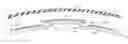
FIG. 2 is a schematical cross-sectional view illustration of adjacent ceramic tiles in the row of ceramic tiles illustrated and through 2-2 in FIG. 1.
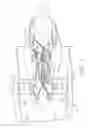
FIG. 3 is a schematical perspective view illustration of adjacent ceramic tiles in the row of ceramic tiles illustrated in FIG. 2.
FIG. 4 is a forward looking aft schematical perspective view illustration of the adjacent ceramic tiles illustrated in FIG. 3.
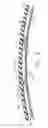
FIG. 5 is a cross-sectional schematical view illustration of one of the adjacent ceramic tiles through 5-5 in FIG. 3.
FIG. 6 is an enlarged cross-sectional schematical illustration of the fan containment system illustrated in FIG. 1 configured when with a composite fan blade casing co-cured with the fan containment system.
FIG. 7 is cross-sectional schematical flow chart illustration of an alternative fan containment system configured when the ceramic tiles are bonded into the fan blade casing after a composite fan blade casing is cured or a non-cured fan blade casing is used.
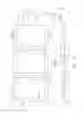
FIG. 8 is a flow chart illustration of a lay-up sequence for the fan containment system illustrated in FIG. 6.
FIG. 9 is a flow chart illustration of a lay-up sequence for the fan containment system illustrated in FIG. 7.
FIG. 10 is a schematical cross sectional view illustration of adjacent alternative ceramic tiles with shiplapped circumferential overlapped ends in the row of ceramic tiles illustrated in FIG. 2.
FIG. 11 is a schematical cross sectional view illustration of an alternative fan containment system with more than one circular row of ceramic tiles.
DESCRIPTION
Illustrated schematically in FIG. 1 is an exemplary turbofan gas turbine engine 10 circumscribed about a centerline axis 8. The engine 10 includes in downstream flow relationship, a fan 12 which receives ambient air 14, a low pressure or booster compressor 16, a high pressure compressor (HPC) 18, a combustor 20 which mixes fuel with the air 14 pressurized by the HPC 18 for generating combustion gases 22 which flow downstream through a high pressure turbine (HPT) 24, and a low pressure turbine (LPT) 26 from which the combustion gases 22 are discharged from the engine 10. A first or high pressure shaft 28 joins the HPT 24 to the HPC 18, and a second or low pressure shaft 30 joins the LPT 26 to both the fan 12 and the low pressure compressor 16.
A fan section 46 of the engine 10 includes a fan case 42 manufactured from, e.g., steel, aluminum, titanium, a composite or any other high-strength material. The fan case 42 circumscribes and surrounds fan blades 44 of the fan 12. A fan blade containment system 40 circumscribes and surrounds the fan 12 and the fan blades 44 to retain any fan blades 44 or fan blade fragments dislodged from the engine fan 12. The fan blade containment system 40 is bonded to and extends radially inwardly from the fan case 42. The fan blade containment system 40 includes a composite or metal outer shell 49 attached to a fan blade casing 48 manufactured of, e.g., steel, aluminum, titanium, or a composite which is a lightweight and high-strength material.
Illustrated in FIG. 2 is the fan blade containment system 40 including at least one circular row or tile layer 52 attached to and located radially inwardly of the shell 49. The circular row or tile layer 52 includes annular ceramic tiles 50 arranged in the circular row or tile layer 52. FIGS. 2-10 illustrate a single circular row or tile layer 52 and FIG. 11 illustrates an alternative fan containment system with more than one circular row of ceramic tiles. The fan containment system illustrated in FIG. 11 includes axially and radially adjacent circular rows 84, 86 of ceramic tiles 50.
Radially inner and outer annular surfaces 56, 58 of the ceramic tiles 50 are bonded to a radially inner composite layer 60 and the shell 49 respectively with elastomeric inner and outer adhesive layers 63, 65 respectively. The inner and outer annular surfaces 56, 58 are cylindrical as indicated in FIGS. 4 and 5. FIG. 4 is an axial view of three of the ceramic tiles 50 illustrating the circular inner and outer annular surfaces 56, 58 as viewed axially. FIG. 5 is a circumferential view taken through 5-5 of the ceramic tile 50 illustrated in FIG. 3 as viewed in the circumferential as indicated by the arrows in FIG. 3. Thus, illustrating the ceramic tiles 50 are cylindrical and curved about the centerline axis 8 illustrated in FIG. 1.
The ceramic tiles 50 illustrated in FIGS. 2-5 have overlapped edges 61. The overlapped edges 61 are illustrated herein as circumferentially and radially facing scarfed edges 62 along circumferential edges 83 of the ceramic tiles 50. The scarfed edges 62 are illustrated herein as bevels 64 in FIGS. 2-5 and as rabbets 66 in FIG. 10. The bevels 64 and the rabbets 66 of circumferentially adjacent ceramic tiles 50 in the tile layer 52 overlap and are shaped to mate along oppositely facing surfaces 70. A scarf may be either of the chamfered or cutaway ends that fit together to form a scarf joint. Scarf is a term that may also be an in-line joint made by chamfering, halving, or notching two pieces to correspond and lapping them such as a shiplap joint with rabbets. The scarfed edges 62 of the ceramic tiles 50 help prevent released fan blades 44 or fan blade fragments dislodged from the engine fan 12 from penetrating between the ceramic tiles 50 directly into the shell 49. The ceramic tiles 50 also have axially forward and aft facing bevels 67, 69 as illustrated in FIG. 5.
The inner and outer adhesive layers 63, 65 may be elastomeric adhesive layers 72 which may be made from thin foam tape or elastomeric layer or film of controlled thickness (e.g. variance ±0.002 inches) covered on at least one side with a pressure sensitive adhesive compatible with the mating structure. The elastomeric adhesive layer 72 is applied to the ceramic tiles 50 for attaching the radially inner and outer annular surfaces 56, 58 of the ceramic tiles 50 to the radially inner composite layer 60 and the shell 49 respectively. Edge adhesive layers 76 which may be in the form of an elastomeric adhesive layer 72 is also applied to cover the overlapped edges 61, such as the scarfed edges 62, of the ceramic tiles 50. Alternatively, the inner and outer adhesive layers 63, 65 and the edge adhesive layers 76 may be made from thin silicone (or other elastomer capable of handling high temperatures and pressures) sheet with pressure sensitive film adhesive. Non-exclusive examples of other elastomers are nitrile rubber, EPDM, fluorinated elastomers, and polyurethanes. Elastomeric adhesive layers may be disposed between the axially and radially adjacent circular rows 84, 86 of ceramic tiles 50 In the fan containment system illustrated in FIG. 11.
One suggested material for the elastomeric adhesive layers 72 is a double-sided adhesive foam tape also referred to as an elastomeric adhesive tape such as VHB (4646 or 4611) sold by and a trademark of 3M which is typically used in automotive, construction or wind energy applications. Elastomeric polyurethane tape such as 3M's Polyurethane Protective Tape (e.g. 8734NA or 8730NA) designed as an erosion film may also be used. A thin silicone sheeting (or other elastomer capable of handling autoclave temperatures and pressures) with pressure sensitive film adhesive may be another alternative elastomeric adhesive layer 72.
The foam tape includes a flexible foam core with adhesive on two opposite sides of the foam tape. The foam tape is a double-sided adhesive bonding tape used to bond glass, wood, steel, concrete, foam, and plastic together with strength and speed needed for permanent, structural and repositionable applications. VHB tape is known for providing shear strength, conformality, surface adhesion and temperature resistance. 3M VHB tapes are known for their use as high-strength bonding tape which “permanently” adheres one substrate to another while spreading the stress load across the entire length of the joint. 3M VHB tapes are made with acrylic foam which is viscoelastic in nature. This gives the foam energy absorbing and stress relaxing properties which provides these tapes with their unique characteristics.
The foam tape is wrapped around the ceramic tiles 50 such that it forms a controlled thin grout line 73 between ceramic tiles 50 when they are assembled in the tile layer 52. The foam tape includes a very compliant foam elastomeric layer or film which reduces interfacial stresses between the ceramic tiles 50 and a containment structure, which is illustrated herein by the outer shell 49. The foam tape has consistent thickness with sufficient compliance to manage tolerance mismatch between the ceramic tiles 50 and the fan blade casing 48. Pressure sensitive adhesive on the foam tape holds the ceramic tiles 50 in place within seconds and allows the next step of the process of making the fan blade containment system 40 without waiting for cure. The foam tape retains its elastomeric characteristic after autoclave or oven curing.
The tile layer 52 of the ceramic tiles 50 may be attached to the fan blade casing 48 either before or after curing the layers of fan blade containment system 40. The autoclave or oven cures the inner composite layer 60 to which the ceramic tiles 50 are bonded. The autoclave or oven may also be used to cure the outer shell 49 if it is made of a composite material and to which the ceramic tiles 50 are bonded. The curing may be performed after the ceramic tiles 50 are bonded to the inner composite layer 60 and the composite outer shell 49 with the foam tape or other elastomeric adhesive layer 72 as illustrated in FIG. 2.
Illustrated in FIGS. 6 and 7 are two different configurations of the fan blade containment system 40. The configuration illustrated in FIG. 6 includes the ceramic tiles 50 bonded to the composite outer shell 49 before curing. The inner composite layer 60 and the composite outer shell 49 are co-cured with the ceramic tiles 50 disposed therebetween. The configuration illustrated in FIG. 7 includes the ceramic tiles 50 bonded to the metallic or composite metal outer shell 49 and to the inner composite layer 60 after the composite outer shell 49 had already been cured. Also illustrated in FIGS. 6 and 7 is a lightweight core 74 made of a material such as honeycomb core extending radially inwardly from and attached to the fan blade containment system 40 including the ceramic tiles 50 between the outer shell 49 and the inner composite layer 60. An abradable layer 78 extending radially inwardly from and attached to the core 74 provides a seal for tips 43 of the fan blades 44.
Illustrated in FIG. 8 are four steps used in an exemplary method for forming a lay-up 80 for co-curing the inner composite layer 60, composite outer shell 49, and the tile layer 52 of the ceramic tiles 50 disposed therebetween to make the fan blade containment system 40 Illustrated in FIGS. 2 and 6. Step 1 includes laying up the inner composite layer 60 on a mold or tool 77. Step 2 includes applying the elastomeric adhesive layer 72 such as a thin foam or elastomeric layer or film containing double-sided adhesive such as a VHB tape on the radially inner annular surfaces 56 and overlapped edges 61 such as the circumferentially facing scarfed edges 62 of the ceramic tiles 50. Step 2 further includes forming the circular row or layer tile layer 52 of the ceramic tiles 50 on the inner composite layer 60. Step 3 includes applying the elastomeric adhesive layer 72 on the outer annular surfaces 58 of the ceramic tiles 50. Step 4 includes laying up the composite outer shell 49 on the elastomeric adhesive layer 72 on the outer annular surfaces 58 of the ceramic tiles 50. The lay-up 80 is then cured such as by autoclaving to form the fan blade containment system 40.
Illustrated in FIG. 9 are three steps used in an exemplary method for forming by bonding together layers of the fan blade containment system 40 illustrated in FIGS. 2 and 7. The fan blade containment system 40 including an inner composite layer 60, a metal or cured composite outer shell 49, and the tile layer 52 of the ceramic tiles 50 disposed therebetween. Step 1 includes applying the elastomeric adhesive layer 72 such as a thin foam or elastomeric layer or film containing double-sided adhesive such as a VHB tape on the radially outer annular surfaces 58 and overlapped edges 61 such as the circumferentially facing scarfed edges 62 of the ceramic tiles 50. Then apply the ceramic tiles 50 to the metal or cured composite outer shell 49 arranged to form the tile layer 52 on and extending radially inwardly from the outer shell 49. Step 2 includes applying the elastomeric adhesive layer 72 on the inner annular surfaces 56 of the ceramic tiles 50. Step 3 includes laying up a composite fabric 82 on the elastomeric adhesive layer 72 covering the inner annular surfaces 56 of the ceramic tiles 50. Another cure step is required to cure the inner composite fabric 82 layer.
While there have been described herein what are considered to be preferred and exemplary embodiments of the present invention, other modifications of the invention shall be apparent to those skilled in the art from the teachings herein and, it is, therefore, desired to be secured in the appended claims all such modifications as fall within the true spirit and scope of the invention.
Accordingly, what is desired to be secured by Letters Patent of the United States is the invention as defined and differentiated in the following claims:
Claims
What is claimed is:1. A fan blade containment system comprising:
annular ceramic tiles arranged in at least one circular tile layer attached to and extending radially inwardly from a shell,
radially outer annular surfaces of the ceramic tiles bonded to the shell with an elastomeric outer adhesive layer,
circumferentially and radially facing overlapped edges along circumferential edges of the ceramic tiles,
elastomeric adhesive layers between circumferentially adjacent ones of the overlapped edges, and
the overlapped edges of the circumferentially adjacent ones of the ceramic tiles in the tile layer overlap and mate along oppositely facing surfaces of the adjacent ones of the ceramic tiles.
2. The system as claimed in claim 1, further comprising radially inner annular surfaces of the ceramic tiles bonded to a radially inner composite layer with an elastomeric inner adhesive layer.
3. The system as claimed in claim 2, further comprising the inner and outer adhesive layers and the elastomeric adhesive layer including a double-sided adhesive foam tape.
4. The system as claimed in claim 2, further comprising the inner and outer adhesive layers and the elastomeric adhesive layer having controlled thicknesses variances of about +0.002 inches.
5. The system as claimed in claim 2, further comprising the overlapped edges including scarfed edges, bevels, or rabbets.
6. The system as claimed in claim 2, further comprising the shell made of a metal or composite material.
7. The system as claimed in claim 2, further comprising the inner composite layer and the composite outer shell co-cured with the ceramic tiles therebetween.
8. The system as claimed in claim 2, further comprising the ceramic tiles having been bonded to the composite outer shell and to the inner composite layer after the composite outer shell had already been cured.
9. A gas turbine engine fan section comprising:
a fan case circumscribing fan blades of a fan,
a fan blade containment system circumscribing the fan blades and bonded to and extending radially inwardly from the fan case,
a fan blade containment system including annular ceramic tiles arranged in at least one circular tile layer attached to and extending radially inwardly from a shell,
radially outer annular surfaces of the ceramic tiles bonded to the shell with an elastomeric outer adhesive layer,
circumferentially and radially facing overlapped edges along circumferential edges of the ceramic tiles,
elastomeric adhesive layers between circumferentially adjacent ones of the overlapped edges, and
the overlapped edges of the circumferentially adjacent ones of the ceramic tiles in the tile layer overlap and mate along oppositely facing surfaces of the adjacent ones of the ceramic tiles.
10. The fan section as claimed in claim 9, further comprising radially inner annular surfaces of the ceramic tiles bonded to a radially inner composite layer with an elastomeric inner adhesive layer.
11. The fan section as claimed in claim 10, further comprising the inner and outer adhesive layers and the elastomeric adhesive layer including a double-sided adhesive foam tape.
12. The fan section as claimed in claim 10, further comprising the overlapped edges including scarfed edges, bevels, or rabbets.
13. The fan section as claimed in claim 10, further comprising the shell made of a metal or composite material.
14. The fan section as claimed in claim 10, further comprising the inner composite layer and the composite outer shell co-cured with the ceramic tiles therebetween.
15. The fan section as claimed in claim 10, further comprising the ceramic tiles having been bonded to the composite outer shell and to the inner composite layer after the composite outer shell had been cured or the ceramic tiles having been bonded to the composite outer shell and to the inner composite layer after the composite outer shell had already been cured.
16. The fan section as claimed in claim 10, further comprising a core extending radially inwardly from and attached to the fan blade containment system and an abradable layer extending radially inwardly from and attached to the core to provide a seal for tips of the fan blades.
17. A method of forming a fan blade containment system for a turbofan gas turbine engine, the method comprising steps of:
1. forming a lay-up for co-curing by laying up an inner composite layer on a mold or tool,
2. forming a circular row or layer tile layer of the ceramic tiles on the inner composite layer,
3. applying an elastomeric adhesive layer on outer annular surfaces of the ceramic tiles,
4. laying up a composite outer shell on the elastomeric adhesive layer on the outer annular surfaces of the ceramic tiles, and
5. curing the lay-up by co-curing the inner composite layer, composite outer shell, and the circular row or tile layer of the ceramic tiles disposed therebetween.
18. The method as claimed in claim 17, further comprising in step 2 applying another elastomeric adhesive layer on radially inner annular surfaces of the ceramic tiles before forming the circular row or layer tile layer of the ceramic tiles on the inner composite layer.
19. The method as claimed in claim 18, further comprising in step 2 applying the elastomeric adhesive layer on circumferentially facing overlapped edges of the ceramic tiles.
20. The method as claimed in claim 19 wherein the elastomeric adhesive layer is foam tape including a flexible foam core with adhesive on two opposite sides of the foam tape.
21. The method as claimed in claim 19, further comprising controlling thicknesses variances of the inner and outer adhesive layers and the elastomeric adhesive layer to about ±0.002 inches when the applying the inner and outer adhesive layers and the elastomeric adhesive layer.
22. A method of forming a fan blade containment system for a turbofan gas turbine engine, the method comprising steps of:
1. applying an elastomeric adhesive layer on radially outer annular surfaces and circumferentially facing overlapped edges of a plurality of ceramic tiles,
2. forming at least one circular row or layer tile layer of the ceramic tiles on and extending radially inwardly from an outer shell, and
3. laying up a composite fabric on the inner annular surfaces of the ceramic tiles.
23. The method as claimed in claim 22, further comprising in step 3 applying another elastomeric adhesive layer on inner annular surfaces of the ceramic tiles before the laying up of the composite fabric on the inner annular surfaces of the ceramic tiles.
24. The method as claimed in claim 23 wherein the elastomeric adhesive layer is foam tape including a flexible foam core with adhesive on two opposite sides of the foam tape.
Images & Drawings included:
Sources:
- United States Patent and Trademark Office - verify current appl. status at the USPTO↗
Recent applications in this class:
- » 20250237233 2025-07-24
IMPELLER CONTAINMENT SYSTEM - » 20250146510 2025-05-08
MOTOR AND AXIAL FAN - » 20240410392 2024-12-12
HYBRID SHROUD IMPELLER - » 20240318665 2024-09-26
Light emitting fan - » 20240271637 2024-08-15
Axial fan - » 20240159247 2024-05-16
Casing Treatment for Gas Turbine Engines - » 20240093699 2024-03-21
Motor and axial fan - » 20240060510 2024-02-22
METHOD AND APPARATUS FOR ENDWALL TREATMENTS - » 20230120451 2023-04-20
Motor and axial fan - » 20220042521 2022-02-10
Fan motor and manufacturing method of the same
Recent applications for this Assignee:
- » 20250250942 2025-08-07
Overall Engine Efficiency Rating for Turbomachine Engines - » 20250243827 2025-07-31
MULTIPLE-FLOW AIRCRAFT TURBINE ENGINE - » 20250229333 2025-07-17
SYSTEMS AND METHODS FOR SMOOTHING A CONTOUR OF AN OBJECT FORMED DURING ADDITIVE MANUFACTURING - » 20250224115 2025-07-10
TURBINE ENGINE HAVING A COMBUSTION SECTION WITH A FUEL SUPPLY ASSEMBLY - » 20250223929 2025-07-10
UNDUCTED PROPELLER GAS TURBINE COMPRISING A COOLING AIR CHANNEL AND A VARIABLE BLEED VALVE EJECTION CHANNEL - » 20250222519 2025-07-10
ADDITIVE MANUFACTURING SUPPORTS AND METHODS FOR USING SAME IN ADDITIVELY MANUFACTURING PARTS - » 20250215830 2025-07-03
SUSPENSION OF A TRIPLE-FLOW AIRCRAFT TURBINE ENGINE - » 20250215826 2025-07-03
GAS TURBINE ENGINE - » 20250215811 2025-07-03
SYSTEMS AND METHODS FOR ATTACHMENT OF MATERIALS HAVING DIFFERENT THERMAL EXPANSION COEFFICIENTS - » 20250207534 2025-06-26
GAS TURBINE ENGINES AND EPICYCLIC GEARBOXES WITH PLANET GEAR CLEARANCES