Method for manufacture and structure of multiple electrochemistries and energy gathering components within a unified structure
US20170250441A1
2017-08-31
15/595,872
2017-05-15
✅ Patent granted
US 11,539,070 B2
2022-12-27
-
-
Kwang Han
Faegre Drinker Biddle & Reath LLP
2037-05-15
Abstract:
A method for using an integrated battery and device structure includes using two or more stacked electrochemical cells integrated with each other formed overlying a surface of a substrate. The two or more stacked electrochemical cells include related two or more different electrochemistries with one or more devices formed using one or more sequential deposition processes. The one or more devices are integrated with the two or more stacked electrochemical cells to form the integrated battery and device structure as a unified structure overlying the surface of the substrate. The one or more stacked electrochemical cells and the one or more devices are integrated as the unified structure using the one or more sequential deposition processes. The integrated battery and device structure is configured such that the two or more stacked electrochemical cells and one or more devices are in electrical, chemical, and thermal conduction with each other.
Inventors:
- Fabio ALBANO 23 🇺🇸 Ann Arbor, MI, United States
- Ann Marie SASTRY 70 🇺🇸 Ann Arbor, MI, United States
- Chia-Wei WANG 35 🇺🇸 Ypsilanti, MI, United States
Assignee:
- Sakti3, Inc. 45 🇺🇸 Ann Arbor, MI, United States
Applicant:
Interested in similar patents?
Get notified when new applications in this technology area are published.
Classification:
H01M4/38 IPC
Electrodes; Electrodes composed of, or comprising, active material; Selection of substances as active materials, active masses, active liquids of elements or alloys
H01L31/1804 » CPC further
Semiconductor devices sensitive to infra-red radiation, light, electromagnetic radiation of shorter wavelength or corpuscular radiation and specially adapted either for the conversion of the energy of such radiation into electrical energy or for the control of electrical energy by such radiation; Processes or apparatus specially adapted for the manufacture or treatment thereof or of parts thereof; Details thereof; Processes or apparatus specially adapted for the manufacture or treatment of these devices or of parts thereof comprising only elements of Group IV of the Periodic System
H01M4/382 » CPC further
Electrodes; Electrodes composed of, or comprising, active material; Selection of substances as active materials, active masses, active liquids of elements or alloys; Alkaline or alkaline earth metals elements Lithium
H01G11/34 » CPC further
Hybrid capacitors, i.e. capacitors having different positive and negative electrodes; Electric double-layer [EDL] capacitors; Processes for the manufacture thereof or of parts thereof; Electrodes characterised by their material; Carbon-based characterised by carbonisation or activation of carbon
H01M10/0436 » CPC further
Secondary cells; Manufacture thereof; Construction or manufacture in general Small-sized flat cells or batteries for portable equipment
H01M10/42 IPC
Secondary cells; Manufacture thereof Methods or arrangements for servicing or maintenance of secondary cells or secondary half-cells
H01L31/022441 » CPC further
Semiconductor devices sensitive to infra-red radiation, light, electromagnetic radiation of shorter wavelength or corpuscular radiation and specially adapted either for the conversion of the energy of such radiation into electrical energy or for the control of electrical energy by such radiation; Processes or apparatus specially adapted for the manufacture or treatment thereof or of parts thereof; Details thereof; Details; Electrodes for devices characterised by at least one potential jump barrier or surface barrier for solar cells Electrode arrangements specially adapted for back-contact solar cells
H01M4/0402 » CPC further
Electrodes; Electrodes composed of, or comprising, active material; Processes of manufacture in general Methods of deposition of the material
H01M4/045 » CPC further
Electrodes; Electrodes composed of, or comprising, active material; Processes of manufacture in general by electrochemical processing Electrochemical coating; Electrochemical impregnation
H01M4/0419 » CPC further
Electrodes; Electrodes composed of, or comprising, active material; Processes of manufacture in general; Methods of deposition of the material involving spraying
H01M4/0421 » CPC further
Electrodes; Electrodes composed of, or comprising, active material; Processes of manufacture in general; Methods of deposition of the material involving vapour deposition
H01M4/0423 » CPC further
Electrodes; Electrodes composed of, or comprising, active material; Processes of manufacture in general; Methods of deposition of the material involving vapour deposition Physical vapour deposition
H01M4/0426 » CPC further
Electrodes; Electrodes composed of, or comprising, active material; Processes of manufacture in general; Methods of deposition of the material involving vapour deposition; Physical vapour deposition Sputtering
H01M4/0428 » CPC further
Electrodes; Electrodes composed of, or comprising, active material; Processes of manufacture in general; Methods of deposition of the material involving vapour deposition Chemical vapour deposition
H01M4/5825 » CPC further
Electrodes; Electrodes composed of, or comprising, active material; Selection of substances as active materials, active masses, active liquids of inorganic compounds other than oxides or hydroxides, e.g. sulfides, selenides, tellurides, halogenides or LiCoF; of polyanionic structures, e.g. phosphates, silicates or borates Oxygenated metallic salts or polyanionic structures, e.g. borates, phosphates, silicates, olivines
H01G11/04 » CPC further
Hybrid capacitors, i.e. capacitors having different positive and negative electrodes; Electric double-layer [EDL] capacitors; Processes for the manufacture thereof or of parts thereof Hybrid capacitors
H01M10/4264 » CPC further
Secondary cells; Manufacture thereof; Methods or arrangements for servicing or maintenance of secondary cells or secondary half-cells; Structural combination with electronic components, e.g. electronic circuits integrated to the outside of the casing with capacitors
H01M10/465 » CPC further
Secondary cells; Manufacture thereof; Methods or arrangements for servicing or maintenance of secondary cells or secondary half-cells; Accumulators structurally combined with charging apparatus with solar battery as charging system
H01M16/003 » CPC further
Structural combinations of different types of electrochemical generators of fuel cells with other electrochemical devices, e.g. capacitors, electrolysers
H01M16/006 » CPC further
Structural combinations of different types of electrochemical generators of fuel cells with other electrochemical devices, e.g. capacitors, electrolysers of fuel cells with rechargeable batteries
H01M2008/1095 » CPC further
Fuel cells; Manufacture thereof; Fuel cells with solid electrolytes Fuel cells with polymeric electrolytes
H01M2300/0068 » CPC further
Electrolytes; Non-aqueous electrolytes; Solid electrolytes inorganic
Y02E60/10 » CPC further
Enabling technologies; Technologies with a potential or indirect contribution to GHG emissions mitigation Energy storage using batteries
Y02E60/10 » CPC further
Enabling technologies; Technologies with a potential or indirect contribution to GHG emissions mitigation Energy storage using batteries
Y10T29/49108 » CPC further
Metal working; Method of mechanical manufacture; Electrical device making Electric battery cell making
Y10T29/49115 » CPC further
Metal working; Method of mechanical manufacture; Electrical device making; Electric battery cell making including coating or impregnating
H01M10/04 IPC
Secondary cells; Manufacture thereof Construction or manufacture in general
H01M4/04 IPC
Electrodes; Electrodes composed of, or comprising, active material Processes of manufacture in general
H01M4/58 IPC
Electrodes; Electrodes composed of, or comprising, active material; Selection of substances as active materials, active masses, active liquids of inorganic compounds other than oxides or hydroxides, e.g. sulfides, selenides, tellurides, halogenides or LiCoF; of polyanionic structures, e.g. phosphates, silicates or borates
H01M6/40 » CPC further
Primary cells; Manufacture thereof Printed batteries, e.g. thin film batteries
H01M16/00 » CPC further
Structural combinations of different types of electrochemical generators
H01M8/10 IPC
Fuel cells; Manufacture thereof Fuel cells with solid electrolytes
H01L31/0224 IPC
Semiconductor devices sensitive to infra-red radiation, light, electromagnetic radiation of shorter wavelength or corpuscular radiation and specially adapted either for the conversion of the energy of such radiation into electrical energy or for the control of electrical energy by such radiation; Processes or apparatus specially adapted for the manufacture or treatment thereof or of parts thereof; Details thereof; Details Electrodes
H01L31/18 IPC
Semiconductor devices sensitive to infra-red radiation, light, electromagnetic radiation of shorter wavelength or corpuscular radiation and specially adapted either for the conversion of the energy of such radiation into electrical energy or for the control of electrical energy by such radiation; Processes or apparatus specially adapted for the manufacture or treatment thereof or of parts thereof; Details thereof Processes or apparatus specially adapted for the manufacture or treatment of these devices or of parts thereof
H01M10/46 IPC
Secondary cells; Manufacture thereof; Methods or arrangements for servicing or maintenance of secondary cells or secondary half-cells Accumulators structurally combined with charging apparatus
H01M10/0562 » CPC main
Secondary cells; Manufacture thereof; Accumulators with non-aqueous electrolyte characterised by the materials used as electrolytes, e.g. mixed inorganic/organic electrolytes the electrolyte being constituted of inorganic materials only Solid materials
H01M4/505 » CPC further
Electrodes; Electrodes composed of, or comprising, active material; Selection of substances as active materials, active masses, active liquids of inorganic oxides or hydroxides of manganese of mixed oxides or hydroxides containing manganese for inserting or intercalating light metals, e.g. LiMnO or LiMnOxFy
H01M12/08 » CPC further
Hybrid cells; Manufacture thereof composed of a half-cell of a fuel-cell type and a half-cell of the secondary-cell type
H02S40/38 » CPC further
Components or accessories in combination with PV modules, not provided for in groups -; Electrical components Energy storage means, e.g. batteries, structurally associated with PV modules
Description
REFERENCE TO RELATED APPLICATIONS
This application is a continuation of U.S. patent application Ser. No. 14/060,387, filed Oct. 22, 2013, which is a continuation of U.S. patent application Ser. No. 13/465,243 filed May 7, 2012, now U.S. Pat. No. 8,597,722, which is a continuation of U.S. patent application Ser. No. 12/614,169 filed Nov. 6, 2009, now U.S. Pat. No. 8,192,789, which claims priority to U.S. Provisional Patent Application No. 61/112,707 filed Nov. 7, 2008, the entire contents of which are incorporated herein by reference.
SUMMARY OF THE INVENTION
According to the present invention, techniques related to energy devices are provided. More particularly, embodiments of the present invention relate to methods to design, manufacture, and structure a multi-component energy device having a unified structure. The individual components can include electrochemical cells, photovoltaic cells, fuel-cells, capacitors, ultracapacitors, thermoelectric, piezoelectric, micro electromechanical turbines, or energy scavengers. The methods and systems described herein are also applicable to a variety of energy systems.
According to an embodiment of the present invention, a method for using an integrated battery and device structure is provided. The method includes using two or more stacked electrochemical cells integrated with each other formed overlying a surface of a substrate. The two or more stacked electrochemical cells include related two or more different electrochemistries with one or more devices formed using one or more sequential deposition processes. The one or more devices are integrated with the two or more stacked electrochemical cells to form the integrated battery and device structure as a unified structure overlying the surface of the substrate. The one or more stacked electrochemical cells and the one or more devices are integrated as the unified structure using the one or more sequential deposition processes. The integrated battery and device structure is configured such that the two or more stacked electrochemical cells and one or more devices are in electrical, chemical, and thermal conduction with each other.
Numerous benefits are achieved by way of the present invention over conventional techniques. For example, electrochemical cells described herein present multiple chemistries to accommodate a wider range of voltage and current compared to individual ones. Additionally, energy-scavenging elements are utilized to collect energy and replenish it to other components within the unified structure. Depending upon the embodiment, one or more of these benefits may be achieved. These and other benefits will be described in more detail throughout the present specification and more particularly below.
These and other objects and features of the present invention and the manner of obtaining them will become apparent to those skilled in the art, and the invention itself will be best understood by reference to the following detailed description read in conjunction with the accompanying drawings.
BRIEF DESCRIPTION OF THE DRAWINGS
FIG. 1—Simplified cross-sectional view of a unified structure including an integrated silicon (Si) solar cell and a thin film battery.
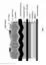
FIG. 2—Simplified cross-sectional view of a unified structure including two integrated thin film batteries having different chemistry.
FIG. 3—Simplified cross-sectional view of a unified structure including an integrated hydrogen/oxygen fuel-cell and a thin film battery.
FIG. 4—Simplified cross sectional view of a unified structure including an integrated ultra-capacitor and a thin film battery.
DETAILED DESCRIPTION OF THE INVENTION
EXAMPLE 1
A Unified Structure Including a Silicon (Si) Solar Cell and a Thin Film Battery and Their Manufacturing Method
Preparing a stacked cell on the back surface of a silicon (Si) solar cell as shown in FIG. 1 can be achieved by forming the cell components using physical vapor deposition. A solar cell exploiting p-type silicon is constructed using traditional Si wafers (Czochralski method). After forming a p-n junction by diffusing phosphorous (P) into the wafer, an aluminum (Al) back contact is created (metal back contact in FIG. 1), onto the p+ doped region (lower side) of the silicon wafer, using physical vapor deposition. The aluminum layer is grown to a thickness of 1-2 μm.
After the back metal contact is created, a separation layer of electrically insulating and thermally conductive aluminum nitride (AlN), having a thickness of 3-5 μm, is fabricated onto the aluminum layer using PVD. This layer has the function of removing heat from the two elements and convey it to a heat sink.
After the cooling element is completed, the battery components are deposited sequentially and conformally by a physical vapor deposition (PVD) process: an aluminum (Al) current collector layer (1-3 μm thick), a lithium manganese oxide (LiMn2O4) cathode layer (3-5 μm thick), a lithium phosphorous oxynitride (UPON) ceramic electrolyte layer (1-3 μm thick), a lithium (Li) metal anode layer (3-5 μm thick), and a copper (Cu) current collector layer (1-3 μm thick), respectively.
EXAMPLE 2
A Unified Structure Including Two Thin Film Batteries Having Different Chemistry and Their Manufacturing Method
Two stacked cells having different electrochemistries are fabricated onto each other by using physical vapor deposition as reported in FIG. 2.
The first battery components are deposited using a PVD process onto an aluminum (Al) metal film used as cathode current collector: a lithium iron phosphate (LiFePO4) cathode layer (3-5 μm thick), a lithium phosphorous oxynitride (LIPON) ceramic electrolyte layer (1-3 μm thick), a lithium (Li) metal anode layer (3-5 μm thick) and a copper (Cu) current collector layer (1-3 μm thick), respectively.
After the copper (Cu) metal current collector is created, a separation layer of electrically insulating and thermally conductive aluminum nitride (AlN), having a thickness of 3-5 μm, is fabricated onto the copper layer using PVD. This layer has the function of removing heat from the two elements and convey it to a heat sink.
After the cooling element is completed, the second battery components are deposited sequentially and conformally by a PVD process: an aluminum (Al) current collector layer (1-3 μm thick), a lithium manganese oxide (LiMn2O4) cathode layer (3-5 μm thick), a lithium phosphorous oxynitride (LIPON) ceramic electrolyte layer (1-3 μm thick), a lithium (Li) metal anode layer (3-5 μm thick) and a copper (Cu) current collector layer (1-3 μm thick), respectively.
EXAMPLE 3
A Unified Structure Including a Fuel-Cell and a Thin Film Battery and Their Manufacturing Method
Preparing a stacked cell on the back surface of a proton-exchange membrane (PEM) fuel-cell as shown in FIG. 3 can be achieved by forming the cell components using physical vapor deposition (PVD). A PEM fuel-cell exploiting proton exchange membranes with high proton conductivity, employing perfluorosulfonate ionomers electrolytes such as Nation®, is constructed using traditional sol-gel methods for fabricating the membrane and wet slurry for the electrodes.
After assembly of the fuel-cell a separation layer of electrically insulating and thermally conductive aluminum nitride (AlN), having a thickness of 3-5 μm, is fabricated onto the fuel-cell current collector using PVD. This layer has the function of removing heat from the two elements and conveying it to a heat sink.
After the cooling element is completed, the battery components are deposited sequentially and conformally by a PVD process. Respectively an aluminum (Al) current collector layer (1-3 μm thick), a lithium manganese oxide (LiMn2O4) cathode layer (3-5 μm thick), a lithium phosphorous oxynitride (UPON) ceramic electrolyte layer (1-3 μm thick), a lithium (Li) metal anode layer (3-5 μm thick) and a copper (Cu) current collector layer (1-3 μm thick).
EXAMPLE 4
A Unified Structure Including an Ultra-Capacitor and a Thin Film Battery and Their Manufacturing Method
Preparing a stacked cell on the back surface of an electrochemical double layer capacitor (EDLC), which is also known as an ultra-capacitor) as shown in FIG. 3 can be achieved by forming the cell components using PVD. In such a hybrid system, the battery provides high energy density while the EDLC enables high power capability in the system.
EDLCs describe a class of energy-storage devices that incorporate active materials including high-surface-area carbons (activated carbons), electroactive polymers, transition metal oxides and nitrides. The separation materials include advanced dielectrics, conventional and advanced polymer electrolytes and ionic conducting materials. Electrodes arrangement can be symmetric or anti-symmetric. In FIG. 4 an anti-symmetric electrode arrangement is presented for the device electrodes. The electrodes of the capacitor can be formed by high-surface-area materials such as activated carbon of high capacitance redox-active materials such as metal oxides (e.g. hydrous ruthenium oxides, RuO2.0.5H2O) prepared by sol-gel methods with capacitance up to 700 F/g. Using anti-symmetric electrodes and different anode and cathode materials resulting in higher working voltages enhances the energy-storage capability of this element.
After assembly of the ultra-capacitor a separation layer of electrically insulating and thermally conductive aluminum nitride (AlN), having a thickness of 3-5 μm, is fabricated onto the dielectric material layer using PVD. This layer has the function of removing heat from the two elements and conveying it to a heat sink.
After the cooling element is completed, the battery components are deposited sequentially and conformally by a PVD process: an aluminum (Al) current collector layer (1-3 μm thick), a lithium manganese oxide (LiMn2O4) cathode layer (3-5 μm thick), a lithium phosphorous oxynitride (LIPON) ceramic electrolyte layer (1-3 μm thick), a lithium (Li) metal anode layer (3-5 μm thick) and a copper (Cu) current collector layer (1-3 μm thick), respectively.
It is also understood that the examples and embodiments described herein are for illustrative purposes only and that various modifications or changes in light thereof will be suggested to persons skilled in the art and are to be included within the spirit and purview of this application and scope of the appended claims.
Claims
1. (canceled)
2. A thin film battery device comprising two or more electro-chemistries, the thin film battery device comprising:
a first thin film battery cell comprising a first cathode layer, a first electrolyte layer, and a first anode layer; and
a second thin film battery cell comprising a second cathode layer, a second electrolyte layer, and a second anode layer,
wherein the second thin film battery cell is deposited on the first thin film battery cell, and the electrochemistry of the first thin film battery cell is different than the electrochemistry of the second thin film battery cell.
3. The thin film battery device of claim 2, comprising a separation layer deposited between the first thin film battery cell and the second thin film battery cell.
4. The thin film battery device of claim 2, wherein the first thin film battery cell comprises a first cathode current collector and a first anode current collector, and wherein the second thin film battery cell comprises a second cathode current collector and a second anode current collector.
5. The thin film battery device of claim 2, wherein the first thin film battery cell and the second thin film battery cell are deposited using a physical vapor deposition (PVD) process.
6. The thin film battery device of claim 2, wherein the first electrolyte layer comprises lithium and the second electrolyte layer comprises lithium.
7. The thin film battery device of claim 2, wherein the first electrolyte layer comprises lithium phosphorous oxynitride (UPON).
8. The thin film battery device of claim 2, wherein the first electrolyte layer is 1-3 μm thick.
9. The thin film battery device of claim 2, wherein the second electrolyte layer comprises lithium phosphorous oxynitride (UPON).
10. The thin film battery device of claim 2, wherein the second electrolyte layer is 1-3 μm thick.
11. The thin film battery device of claim 2, wherein the first cathode layer comprises lithium iron phosphate (LiFePO4).
12. The thin film battery device of claim 2, wherein the first cathode layer is 3-5 μm thick.
13. The thin film battery device of claim 2, wherein the second cathode layer comprises a lithium manganese oxide (LiMn2O4).
14. The thin film battery device of claim 2, wherein the second cathode layer is 3-5 μm thick.
15. The thin film battery device of claim 2, wherein the first anode layer and the second anode layer comprise lithium.
16. The thin film battery device of claim 2, wherein the first anode layer and the second anode layer are 3-5 μm thick.
17. A method of making a thin film battery device comprising two or more electro-chemistries comprising:
forming a first thin film battery cell comprising:
depositing a first cathode layer;
depositing a first electrolyte layer on the first cathode layer; and
depositing a first anode layer on the first electrolyte layer; and
depositing a second thin film battery cell on the first thin film battery cell comprising:
depositing a second cathode layer on a first substrate comprising the first thin film battery cell;
depositing a second electrolyte layer on the second cathode layer;
depositing a second anode layer on the first electrolyte layer,
wherein the electrochemistry of the first thin film battery cell is different than the electrochemistry of the second thin film battery cell.
18. The method of making a thin film battery device of claim 17, wherein the first cathode layer, the first electrolyte layer, the first anode layer, the second cathode layer, the second electrolyte layer, and the second anode layer are deposited using physical vapor deposition processes.
19. The method of making a thin film battery device of claim 17, further comprising depositing separation layer between the first thin film battery cell and the second thin film battery cell.
20. The method of making a thin film battery device of claim 17, wherein the first thin film battery cell comprises a first cathode current collector and a first anode current collector, and wherein the second thin film battery cell comprises a second cathode current collector and a second anode current collector.
21. The method of making a thin film battery device of claim 17, wherein the first electrolyte layer comprises lithium and the second electrolyte layer comprises lithium.
22. The method of making a thin film battery device of claim 17, wherein the first electrolyte layer comprises lithium phosphorous oxynitride (UPON).
23. The method of making a thin film battery device of claim 17, wherein the first electrolyte layer is 1-3 μm thick.
24. The method of making a thin film battery device of claim 17, wherein the second electrolyte layer comprises lithium phosphorous oxynitride (UPON).
25. The method of making a thin film battery device of claim 17, wherein the second electrolyte layer is 1-3 μm thick.
26. The method of making a thin film battery device of claim 17, wherein the first cathode layer comprises lithium iron phosphate (LiFePO4).
27. The method of making a thin film battery device of claim 17, wherein the first cathode layer is 3-5 μm thick.
28. The method of making a thin film battery device of claim 17, wherein the second cathode layer comprises a lithium manganese oxide (LiMn2O4).
29. The method of making a thin film battery device of claim 17, wherein the second cathode layer is 3-5 μm thick.
30. The method of making a thin film battery device of claim 17, wherein the first anode layer and the second anode layer comprise lithium.
31. The method of making a thin film battery device of claim 17, wherein the first anode layer and the second anode layer are 3-5 μm thick.
Images & Drawings included:


Sources:
- United States Patent and Trademark Office - verify current appl. status at the USPTO↗
Similar patent applications:
- » 20100136245
Method for manufacture and structure of multiple electrochemistries and energy gathering components within a unified structure - » 20120219830
Method for manufacture and structure of multiple electrochemistries and energy gathering components within a unified structure - » 20140050857
METHOD FOR MANUFACTURE AND STRUCTURE OF MULTIPLE ELECTROCHEMISTRIES AND ENERGY GATHERING COMPONENTS WITHIN A UNIFIED STRUCTURE
Recent applications in this class:
- » 20250293296 2025-09-18
SOLID-STATE BATTERY - » 20250293295 2025-09-18
SOLID-STATE BATTERY - » 20250293294 2025-09-18
SULFIDE-BASED SOLID ELECTROLYTE WITH IMPROVED DUCTILITY AND FRACTURE STRENGTH - » 20250293293 2025-09-18
SULPHIDE BASED LITHIUM-ION CONDUCTING SOLID ELECTROLYTE AND METHODS FOR THE PRODUCTION THEREOF - » 20250286124 2025-09-11
GARNET MATERIALS FOR LI SECONDARY BATTERIES AND METHODS OF MAKING AND USING GARNET MATERIALS - » 20250286123 2025-09-11
ELECTROLYTE POWDER, SHEET, ELECTROCHEMICAL ELEMENT, AND ELECTRIC POWER STORAGE DEVICE - » 20250286122 2025-09-11
METHODS FOR THE PRODUCTION OF SULPHIDE BASED LITHIUM-ION CONDUCTING SOLID ELECTROLYTE - » 20250286121 2025-09-11
SULPHIDE BASED LITHIUM-ION CONDUCTING SOLID ELECTROLYTE AND METHODS FOR THE PRODUCTION THEREOF - » 20250286120 2025-09-11
STABLE LFP-BASED ALL-SOLID-STATE BATTERY CELL - » 20250286119 2025-09-11
Low-Cost Solid-State Aluminum-Ion Battery
Recent applications for this Assignee:
- » 20180248163 2018-08-30
Barrier for thin film lithium batteries made on flexible substrates and related methods - » 20180138469 2018-05-17
Packaging and termination structure for a solid state battery - » 20180040910 2018-02-08
MANUFACTURE OF HIGH CAPACITY SOLID STATE BATTERIES - » 20170356078 2017-12-14
Thermal evaporation process for manufacture of solid state battery devices - » 20170352922 2017-12-07
Embedded solid-state battery - » 20170352907 2017-12-07
Amorphous cathode material for battery device - » 20170194624 2017-07-06
Phase change material source for physical vapor deposition - » 20160344065 2016-11-24
Electric vehicle propulsion system and method utilizing solid-state rechargeable electrochemical cells - » 20160293907 2016-10-06
Packaging and termination structure for a solid state battery - » 20160240884 2016-08-18
Amorphous cathode material for battery device