Adaptive power display
US20170274487A1
2017-09-28
15/123,941
2015-03-06
✅ Patent granted
US 10,377,005 B2
2019-08-13
WO; PCT/EP2015/054703; 20150306
WO; WO2015/132376; 20150911
Derek D Knight
Davidson, Davidson & Kappel, LLC
2036-01-12
Abstract:
A method to control a power tool, especially a core drill, including a motor as the drive for the power tool, a control unit, a power display, a transmission having at least a first gear and a second gear, a first sensor to detect the rotational speed of at least one component of the transmission and a second sensor to detect the rotational speed of the motor. The method includes the following steps: ascertaining a first rotational speed of the at least one component of the transmission when the transmission has been put into a gear, ascertaining a first rotational speed of the motor when the transmission has been put into a gear, ascertaining the selection of the gear on the basis of a first prescribed ratio of the first rotational speed of the at least one component of the transmission and of the first rotational speed of the motor on the basis of a look-up table, and setting the limit value of the power display on the basis of the look-up table as a function of the gear that has been selected. A power tool for purposes of using the method.
Assignee:
- Hilti Aktiengesellschaft 1,520 Schaan, Liechtenstein
Applicant:
Interested in similar patents?
Get notified when new applications in this technology area are published.
Classification:
B23Q5/142 » CPC main
Driving or feeding mechanisms; Control arrangements therefor; Driving main working members rotary shafts, e.g. working-spindles; Mechanical drives with means for varying the speed ratio step-by-step mechanically-operated
B25F5/001 » CPC further
Details or components of portable power-driven tools not particularly related to the operations performed and not otherwise provided for Gearings, speed selectors, clutches or the like specially adapted for rotary tools
F16H3/005 » CPC further
Toothed gearings for conveying rotary motion with variable gear ratio or for reversing rotary motion the gear-ratio being changed by inversion of torque direction for gearings using gears having orbital motion
H03K5/082 » CPC further
Manipulating of pulses not covered by one of the other main groups of this subclass; Shaping pulses by limiting; by thresholding; by slicing, i.e. combined limiting and thresholding with an adaptive threshold
F16H3/00 IPC
Toothed gearings for conveying rotary motion with variable gear ratio or for reversing rotary motion
B23B35/00 » CPC further
Boring; Drilling
B23B35/00 » CPC further
Methods for boring or drilling, or for working essentially requiring the use of boring or drilling machines; Use of auxiliary equipment in connection with such methods
B28D1/04 IPC
Working stone or stone-like materials, e.g. brick, concrete or glass , not provided for elsewhere; Machines, devices, tools therefor by sawing with circular or cylindrical saw-blades or saw-discs
B28D1/041 » CPC further
Working stone or stone-like materials, e.g. brick, concrete or glass , not provided for elsewhere; Machines, devices, tools therefor by sawing with circular or cylindrical saw-blades or saw-discs with cylinder saws, e.g. trepanning; saw cylinders, e.g. having their cutting rim equipped with abrasive particles
H03K5/08 IPC
Manipulating of pulses not covered by one of the other main groups of this subclass; Shaping pulses by limiting; by thresholding; by slicing, i.e. combined limiting and thresholding
B23B2260/07 » CPC further
Details of constructional elements Gears
B23B2260/128 » CPC further
Details of constructional elements Sensors
B23Q5/14 IPC
Driving or feeding mechanisms; Control arrangements therefor; Driving main working members rotary shafts, e.g. working-spindles; Mechanical drives with means for varying the speed ratio step-by-step
B25F5/00 » CPC further
Details or components of portable power-driven tools not particularly related to the operations performed and not otherwise provided for
B28D7/00 IPC
Accessories specially adapted for use with machines or devices of the preceding groups
F16H3/44 » CPC further
Toothed gearings for conveying rotary motion with variable gear ratio or for reversing rotary motion using gears having orbital motion
G01P3/00 » CPC further
Measuring linear or angular speed; Measuring differences of linear or angular speeds
B28D7/005 » CPC further
Accessories specially adapted for use with machines or devices of the preceding groups Devices for the automatic drive or the program control of the machines
B23B2270/486 » CPC further
Details of turning, boring or drilling machines, processes or tools not otherwise provided for; Measuring or detecting Measurement of rotational speed
Description
The present invention relates to a method to control a power tool, especially a core drill, comprising a motor as the drive for the power tool, a control unit, a power display, a transmission having at least a first gear and a second gear, a first sensor to detect the rotational speed of at least one component of the transmission and a second sensor to detect the rotational speed of the motor.
Moreover, the invention relates to a power tool, especially a core drill, comprising a motor as the drive for the power tool, a control unit, a power display, a transmission having at least a first gear and a second gear, a first sensor to detect the rotational speed of at least one component of the transmission and a second sensor to detect the rotational speed of the motor, for purposes of using the method according to the invention.
BACKGROUND
Power tools such as, for example, core drills, generally serve to drill holes into mineral materials such as for instance, concrete or bricks. In this context, the core drill normally has an electric motor, a transmission, a control unit or control device, a tool socket as well as a tool in the form of a core bit. Via the transmission, the electric motor drives the tool socket together with the tool. The transmission normally has two gears as well as a no-load state, which can be selected or actuated manually by the user of the core drill. By means of the individual gears, the motor speed is stepped up or down to the drive speed in different ways. In this manner, depending on the transmission ratio, either a high rotational speed and a low torque, or else a low rotational speed and a high torque can be available at the core bit. Once the core bit has been made to rotate, it cuts a circular hole into the material by means of its diamond-tipped cutting edge, thereby creating a cylindrical drill core. This drill core is removed from the drilled hole at the end of the drilling or cutting procedure.
A core drill according to the state of the art is disclosed in German patent application DE 10 2011 089 771. This power tool configured as a core drill comprises a drive means with a drive motor and a drive shaft, a driven means with a driven shaft, a transmission with a planetary gear train and an additional gear unit as well as a device for changing between a first and a second gear speed step of the planetary gear train.
SUMMARY OF THE INVENTION
A widespread problem encountered with core drills according to the state of the art is that the limit values for the overload ranges are dimensioned on the basis of the gear that rotates most slowly (that is to say, the highest gear). These limit values, however, are not coordinated with the gears that rotates most quickly (that is to say, the lowest gears). The display of a limit value that is not coordinated with the gear that is currently selected can lead to improper operation of the power tool and to diminished productivity as a result of lower drilling speeds and/or a shortened service life of the power tool.
It is an object of the present invention to solve the above-mentioned problem and provide a method to control a power tool, especially a core drill, as well as to put forward a power tool, especially a core drill, that uses this method, so that greater productivity can be attained when the power tool is used.
For this purpose, a method is shown to control a power tool, especially a core drill, comprising:
-
- a motor as the drive for the power tool;
- a control unit;
- a power display;
- a transmission having at least a first gear and a second gear;
- a first sensor to detect the rotational speed of at least one component of the transmission; and
- a second sensor to detect the rotational speed of the motor.
According to the invention, the following method steps are provided:
-
- ascertaining a first rotational speed of the at least one component of the transmission when the transmission has been put into a gear,
- ascertaining a first rotational speed of the motor when the transmission has been put into a gear,
- ascertaining the selection of the gear on the basis of a first prescribed ratio of the first rotational speed of the at least one component of the transmission and of the first rotational speed of the motor on the basis of a look-up table, and
- setting the limit value of the power display on the basis of the look-up table as a function of the gear that has been selected.
Thanks to the appropriate automatic adaptation of the limit value of the power display to the gear that is currently selected, the user is always able to employ the power tool in the appropriate power range in order to increase the productivity.
Moreover, a power tool is shown, especially a core drill, comprising:
-
- a motor as the drive for the power tool;
- a control unit;
- a power display;
- a transmission having at least a first gear and a second gear;
- a first sensor to detect the rotational speed of at least one component of the transmission; and
- a second sensor to detect the rotational speed of the motor, for purposes of using the method according to the invention.
BRIEF DESCRIPTION OF THE DRAWINGS
Additional advantages can be gleaned from the figure description below. The figures depict various embodiments of the present invention. The figures, the description and the claims contain numerous features in combination. Whenever appropriate, the person skilled in the art will also consider the features individually and unite them to create additional meaningful combinations
The following is shown:
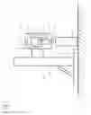
FIG. 1: a power tool configured as a core drill according to the invention, comprising a motor, a control unit, a transmission, a tool configured as a core bit, a first sensor and a second sensor; and
FIG. 2: a first flow chart of the method according to the invention.
DETAILED DESCRIPTION
FIG. 1 shows a power tool 1 configured as a core drill that is attached to a drill stand 2. By means of the drill stand 2, the core drill 1 can be reversibly moved along the double-arrow direction A towards as well as away from the workpiece W that is to be worked. The material W is concrete.
The core drill 1 has a housing 2, a motor 3, a control unit 4, a power display 5, a transmission 6, a driven shaft 7, a tool 8 configured as a core bit, a first sensor 10 to detect the rotational speed of the transmission 6 and a second sensor 20 to detect the rotational speed of the motor 3. Any type of electric motor can be used as the motor 3.
The motor 3 is configured as an electric motor and it serves to drive the core bit 8. The motor 3 has a drive shaft that is detachably connected to the transmission 6. This connection is established by a coupling means. The core bit 8 is made to rotate by means of the transmission 6 and the driven shaft 7. The torque generated in the motor 3 is thus correspondingly transmitted to the core bit 8 in order to cut a hole into the material W.
The transmission 6 has a first gear, a second gear as well as a no-load state, and it is positioned between the drive shaft of the motor 3 and the driven shaft 7. The individual gears can be selected manually by means of a gear-speed selector in order to thus vary the transmission of the rotational speed and of the torque from the motor 3 to the driven shaft 7 or to the core bit 8.
The first sensor 10 is positioned on the transmission 6 in such a way as to detect the rotational speed of at least one component of the transmission 6 relative to the gear that is currently selected. The at least one component of the transmission 6 can be a gear wheel or the like. The second sensor 20, in contrast, is positioned in such a way as to detect that the rotational speed of the motor 3.
The control unit 4 is connected to the first sensor 10 via a first line 11 and to the second sensor 20 via a second line 12, and this is done in such a way that that rotational speed values measured by the sensors 10, 20 are transmitted to the control unit 4. Moreover, the control unit 4 is connected to the motor 3 in such a way that the control unit 4 can vary the rotational speed of the motor 3 directly. Moreover, the control unit 4 is also connected to the power display 5 in such a way that the limit values of the power display 5 can be varied (that is to say, increased or decreased). The control unit 4 has a data memory unit where a look-up table (transmission ratio table) is stored. The gear that is currently selected can be ascertained with this look-up table on the basis of the ratio of the rotational speed of the motor 3 and of the corresponding rotational speed of the transmission 6. Thanks to the connection of the control unit 4 to the motor 3, the control unit 4 can act upon the motor 3, that is to say, it can automatically increase or decrease the rotational speed of the motor 3.
The power display 5 serves to inform the user about the current power level of the core drill 1, that is to say, especially to warn the user against an overload of the core drill 1. For this purpose, the power display 5 is visibly positioned on the housing 2 of the core drill 1 in such a way that the user can see it while working with the core drill 1. The power display 5 comprises a visual scale (graduation) with which the power range and especially the overload range pertaining to the currently selected gear is displayed. As an alternative or in addition to the visual scale, an acoustic display device can be provided which can indicate when the overload range has been reached and especially when it has been exceeded.
FIG. 2 shows the course of the adaptation of the limit value to the selected gear on the basis of the method according to the invention.
Towards this end, in step S1, the first sensor 10 ascertains the rotational speed of the transmission 6.
In step S2, the rotational speed of the motor 3 is ascertained by the second sensor 20.
In step S3, the selected gear is ascertained on the basis of the look-up table stored in the data memory unit as well as on the basis of the ascertained rotational speed of the motor 3 and of the transmission 6.
In step S4, the limit value of the power display 5 is selected on the basis of the look-up table as a function the gear that has been selected.
Claims
What is claimed is:1-2. (canceled)
3. A method to control a power tool including a motor as a drive for the power tool; a controller; a power display; a transmission having a plurality of gears including at least a first gear and a second gear; a first sensor to detect a rotational speed of at least one component of the transmission; and a second sensor to detect a motor rotational speed of the motor, the method comprising the following steps:
ascertaining a first rotational speed of the at least one component of the transmission when the transmission has been put into one of the plurality of gears,
ascertaining a first rotational speed of the motor when the transmission has been put into the one gear,
ascertaining a selection of the one gear as a function of a first prescribed ratio of the first rotational speed of the at least one component of the transmission and of the first rotational speed of the motor on the basis of at least one look-up table, and
setting a limit value of a power display on the basis of the at least one look-up table as a function of the one gear.
4. A method to control a core drill including a motor as a drive for the core drill; a controller; a power display; a transmission having a plurality of gears including at least a first gear and a second gear; a first sensor to detect a rotational speed of at least one component of the transmission; and a second sensor to detect a motor rotational speed of the motor, the method comprising the following steps:
ascertaining a first rotational speed of the at least one component of the transmission when the transmission has been put into one of the plurality of gears,
ascertaining a first rotational speed of the motor when the transmission has been put into the one gear,
ascertaining a selection of the one gear as a function of a first prescribed ratio of the first rotational speed of the at least one component of the transmission and of the first rotational speed of the motor on the basis of at least one look-up table, and
setting a limit value of a power display on the basis of the at least one look-up table as a function of the one gear.
5. A power tool performing the method as recited in claim 2 comprising:
the motor as the drive for the power tool;
the controller;
the power display;
the transmission having at least a first gear and a second gear;
the first sensor to detect the rotational speed of at least one component of the transmission; and
the second sensor to detect the motor rotational speed of the motor.
6. A core drill performing the method as recited in claim 3 comprising:
the motor as the drive for the core drill;
the controller;
the power display;
the transmission having at least a first gear and a second gear;
the first sensor to detect the rotational speed of at least one component of the transmission; and
the second sensor to detect the motor rotational speed of the motor.
Images & Drawings included:

Sources:
- United States Patent and Trademark Office - verify current appl. status at the USPTO↗
Similar patent applications:
- » 20210191489
Content adaptive display power savings systems and methods - » 20200033930
Content adaptive display power savings systems and methods - » 20110244715
Portable display for adaptive power strip - » 20160260409
Integrated circuit for driving adaptable power to display and display device including the same - » 20190259323
Method for adaptively controlling low power display mode and electronic device thereof - » 20140146061
System and method for a wireless display low power managed adapter - » 20130086206
System and method for a wireless display low power managed adapter - » 20160233707
Power Adapter with Charging Data Display - » 20160358526
Load adaptive power management for a display panel - » 20210027722
Adaptive Low Power Touch and Display Device
Recent applications in this class:
- » 20230330798 2023-10-19
MACHINE TOOL - » 20210229230 2021-07-29
Gear Shifting Structure of Power Equipment and Electrically-Driven Tool Comprising Same - » 20210060718 2021-03-04
Tool presetting and/or tool measuring apparatus device, tool presetting and/or tool measuring apparatus and method for operating the tool presetting and/or tool measuring apparatus device - » 20190047102 2019-02-14
Speed change auxiliary device of lathe - » 20170320180 2017-11-09
Machining unit for a machine tool and machine tool with such a machining unit - » 20150122063 2015-05-07
Shifting mechanism for a drill press - » 20140335989 2014-11-13
MACHINE TOOL HAVING A DEVICE FOR SWITCHING BETWEEN A FIRST AND A SECOND TRANSMISSION STAGE BY REVERSING THE DIRECTION OF ROTATION - » 20130047762 2013-02-28
Switchable gear drive for a handheld power tool - » 20050043135 2005-02-24
Multispeed power tool transmission
Recent applications for this Assignee:
- » 20250243117 2025-07-31
Two-component mortar system based on aluminous cement and use thereof - » 20250187982 2025-06-12
USE OF CALCIUM SULFATE IN AN INORGANIC MORTAR SYSTEM BASED ON ALUMINOUS CEMENT AND GROUND-GRANULATED BLAST-FURNACE SLAG TO INCREASE LOAD VALUES - » 20250179346 2025-06-05
TWO-COMPONENT MORTAR SYSTEM BASED ON ALUMINOUS CEMENT AND GROUNDGRANULATED BLAST-FURNACE SLAG AS WELL AS USE THEREOF - » 20250178974 2025-06-05
TWO-COMPONENT MORTAR SYSTEM BASED ON ALUMINOUS CEMENT AND CALCIUM SILICATE AS WELL AS USE THEREOF - » 20250178963 2025-06-05
STABILIZED AQUEOUS COMPOSITION BASED ON BLOCKED CALCIUM SILICATE CEMENT FOR INITIATING SETTING AND HARDENING OF ALUMINOUS CEMENT COMPOSITIONS - » 20250178960 2025-06-05
STABILIZED AQUEOUS COMPOSITION BASED ON BLOCKED GROUND-GRANULATED BLAST-FURNACE SLAG FOR INITIATING SETTING AND HARDENING OF ALUMINOUS CEMENT COMPOSITIONS - » 20250164040 2025-05-22
CAST-IN-PLACE THROUGH-PENETRATION FIRESTOP DEVICE - » 20250115704 2025-04-10
FOAMABLE MULTI-COMPONENT COMPOSITION, AND FOAMED FIRE-PROTECTION PROFILE HAVING TEMPERATURE-REGULATING FILLERS - » 20250090879 2025-03-20
COMPOSITE MATERIAL AND FIRE PROTECTION ELEMENT FOR SEALING PASSAGE OPENINGS AND JOINTS IN COMPONENTS - » 20250088012 2025-03-13
Power tool and method for carrying out charge equalization between accumulators in a power tool