Camera lens
US20170357080A1
2017-12-14
14/913,539
2015-01-07
✅ Patent granted
US 10,254,510 B2
2019-04-09
WO; PCT/CN2015/070301; 20150107
WO; WO2016/109956; 20160714
Alicia M Harrington
Lathrop Gage LLP
2035-01-07
Abstract:
Provided is a camera lens, including a first lens, a second lens, a third lens, a fourth lens, a fifth lens and a sixth lens from an object side of the camera lens to an image side of the camera lens in turn. The first lens is of a positive focal power, an object side surface of the first lens is convex; the second lens is of a negative focal power; the third lens is of a negative focal power, an object side surface of the third lens is concave; the fourth lens is of a positive focal power; the fifth lens is of a positive focal power, an image side surface of the fifth lens is convex; the sixth lens is of a negative focal power, an image side surface of the sixth lens is concave; and the camera lens meets the following formula: 0<f/f4<0.8; 0<T12/T23<0.14.
Inventors:
- Lin Huang 53 🇨🇳 Ningbo, China
- Fujian Dai 157 🇨🇳 Ningbo, China
- Jianke Wenren 58 🇨🇳 Ningbo, China
Assignee:
- ZHEJIANG SUNNY OPTICS CO., LTD. 13 🇨🇳 Ningbo, Zhejiang, China
Applicant:
Interested in similar patents?
Get notified when new applications in this technology area are published.
Classification:
G02B13/0045 » CPC main
Optical objectives specially designed for the purposes specified below; Miniaturised objectives for electronic devices, e.g. portable telephones, webcams, PDAs, small digital cameras characterised by the lens design having at least one aspherical surface having five or more lenses
G02B13/00 IPC
Optical objectives specially designed for the purposes specified below
G02B9/62 » CPC further
Optical objectives characterised both by the number of the components and their arrangements according to their sign, i.e. + or - having six components only
G02B3/02 IPC
Simple or compound lenses with non-spherical faces
G02B13/18 » CPC further
Optical objectives specially designed for the purposes specified below with lenses having one or more non-spherical faces, e.g. for reducing geometrical aberration
Description
FIELD
The present disclosure relates to the field of an imaging technology, in particularly to a camera lens.
BACKGROUND
With the improvements in properties of charge-coupled device (CCD) and complementary metal-oxide semiconductor (CMOS) image sensors, as well as the reduction in size, it requires the corresponding camera lens to meet demands on high imaging quality and miniaturization.
Currently, a common thin camera lens with a high pixel generally encompasses five lenses, for example, an existing camera lens consists of a first lens being of a positive focal power, a second lens being of a negative focal power, a third lens being of a negative focal power, a fourth lens being of a positive focal power and a fifth lens being of a negative focal power from an object side of the camera lens to an image side of the camera lens in turn. Such a system in small aperture of a configuration with a small aperture improves the imaging quality effectively and maintains the miniaturization feature at the same time. However, with the development of portable electronic products, higher demands on features such as the pixel, the imaging quality and the resolution of the miniaturization camera lens are further proposed. In order to meet the demand on the high resolution, a configuration with a large aperture is adopted to meet the demand on the illuminance. However, the known five-lens structure in the configuration with the large aperture cannot further shorten system length to meet the demand on the imaging quality.
SUMMARY
Embodiments of the present disclosure seek to solve at least one of the problems existing in the related art.
An object of the present disclosure is to provide a camera lens, including a first lens, a second lens, a third lens, a fourth lens, a fifth lens and a sixth lens from an object side of the camera lens to an image side of the camera lens in turn, wherein
the first lens is of a positive focal power, an object side surface of the first lens is convex;
the second lens is of a negative focal power;
the third lens is of a negative focal power, an object side surface of the third lens is concave;
the fourth lens is of a positive focal power;
the fifth lens is of a positive focal power, an image side surface of the fifth lens is convex;
the sixth lens is of a negative focal power, an image side of the sixth lens is concave; and
the camera lens meets the following formula:
0<f/f4<0.8;
0<T12/T23<0.14,
wherein f represents an effective focal length of the camera lens,
f4 represents a focal length of the fourth lens,
T12 is a distance between the first lens and the second lens along an axial direction, and
T23 is a distance between the second lens and the third lens along the axial direction.
In some embodiments, an object side surface of the second lens is convex, an image side surface of the second lens is concave; and an object side surface of the fourth lens is convex.
In some embodiments, an object side surface of the sixth lens is concave;
at least one inflection point is present in the object side surface of the sixth lens and the image side surface of the sixth lens; and
the camera lens further includes an aperture stop arranged between a photographed object and the second lens.
In some embodiments, the camera lens meets the following formula:
1<f123/Dr1r6<5.5,
wherein f123 represents a combined focal length of the first lens, the second lens and the third lens, and
Drlr6 represents a distance from the object side surface of the first lens to an image side surface of the third lens along the axial direction.
In some embodiments, the camera lens further meets the following formula:
0.5<f123/f<2.
In some embodiments, the camera lens further meets the following formula:
0<f5/f<1; and
0<(R11+R12)/(R11−R12)<1,
wherein f5 represents a focal length of the fifth lens, and
R11 and R12 represent curvature radiuses of the object side surface and the image side surface of the sixth lens, respectively.
In some embodiments, the first lens, the second lens, the third lens, the fourth lens, the fifth lens and the sixth lens are all made of plastic, and have at least one aspheric shape surface.
In some embodiments, the image side surface of the third lens is convex.
In some embodiments, an image side surface of the first lens is convex, and an object side surface of the fifth lens is convex.
In some embodiments, an image side surface of the fourth lens is concave.
Additional aspects and advantages of embodiments of present disclosure will be given in part in the following descriptions, become apparent in part from the following descriptions, or be learned from the practice of the embodiments of the present disclosure.
BRIEF DESCRIPTION OF THE DRAWINGS
These and other aspects and advantages of embodiments of the present disclosure will become apparent and more readily appreciated from the following descriptions made with reference to the drawings, in which:
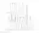
FIG. 1 is a schematic view showing the camera lens according to Example 1 of the present disclosure;
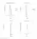
FIG. 2 is a diagram showing a longitudinal aberration curve (mm) of the camera lens in Example 1;
FIG. 3 is a diagram showing an astigmatism curve (mm) of the camera lens in Example 1;
FIG. 4 is a diagram showing a distortion curve (%) of the camera lens in Example 1;
FIG. 5 is a diagram showing a lateral color curve (μm) of the camera lens in Example 1;
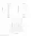
FIG. 6 is a schematic view showing the camera lens according to Example 2 of the present disclosure;
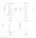
FIG. 7 is a diagram showing a longitudinal aberration curve (mm) of the camera lens in Example 2;
FIG. 8 is a diagram showing an astigmatism curve (mm) of the camera lens in Example 2;
FIG. 9 is a diagram showing a distortion curve (%) of the camera lens in Example 2;
FIG. 10 is a diagram showing a lateral color curve (μm) of the camera lens in Example 2;
FIG. 11 is a schematic view showing the camera lens according to Example 3 of the present disclosure;
FIG. 12 is a diagram showing a longitudinal aberration curve (mm) of the camera lens in Example 3;
FIG. 13 is a diagram showing an astigmatism curve (mm) of the camera lens in Example 3;
FIG. 14 is a diagram showing a distortion curve (%) of the camera lens in Example 3;
FIG. 15 is a diagram showing a lateral color curve (μm) of the camera lens in Example 3;
FIG. 16 is a schematic view showing the camera lens according to Example 4 of the present disclosure;
FIG. 17 is a diagram showing a longitudinal aberration curve (mm) of the camera lens in Example 4;
FIG. 18 is a diagram showing an astigmatism curve (mm) of the camera lens in Example 4;
FIG. 19 is a diagram showing a distortion curve (%) of the camera lens in Example 4;
FIG. 20 is a diagram showing a lateral color curve (μm) of the camera lens in Example 4;
FIG. 21 is a schematic view showing the camera lens according to Example 5 of the present disclosure;
FIG. 22 is a diagram showing a longitudinal aberration curve (mm) of the camera lens in Example 5;
FIG. 23 is a diagram showing an astigmatism curve (mm) of the camera lens in Example 5;
FIG. 24 is a diagram showing a distortion curve (%) of the camera lens in Example 5;
FIG. 25 is a diagram showing a lateral color curve (μm) of the camera lens in Example 5;
FIG. 26 is a schematic view showing the camera lens according to Example 6 of the present disclosure;
FIG. 27 is a diagram showing a longitudinal aberration curve (mm) of the camera lens in Example 6;
FIG. 28 is a diagram showing an astigmatism curve (mm) of the camera lens in Example 6;
FIG. 29 is a diagram showing a distortion curve (%) of the camera lens in Example 6;
FIG. 30 is a diagram showing a lateral color curve (μm) of the camera lens in Example 6;
FIG. 31 is a schematic view showing the camera lens according to Example 7 of the present disclosure;
FIG. 32 is a diagram showing a longitudinal aberration curve (mm) of the camera lens in Example 7;
FIG. 33 is a diagram showing an astigmatism curve (mm) of the camera lens in Example 7;
FIG. 34 is a diagram showing a distortion curve (%) of the camera lens in Example 7;
FIG. 35 is a diagram showing a lateral color curve (μm) of the camera lens in Example 7;
FIG. 36 is a schematic view showing the camera lens according to Example 8 of the present disclosure;
FIG. 37 is a diagram showing a longitudinal aberration curve (mm) of the camera lens in Example 8;
FIG. 38 is a diagram showing an astigmatism curve (mm) of the camera lens in Example 8;
FIG. 39 is a diagram showing a distortion curve (%) of the camera lens in Example 8;
FIG. 40 is a diagram showing a lateral color curve (μm) of the camera lens in Example 8.
DETAILED DESCRIPTION
Embodiments of the present disclosure will be described in detail in the following descriptions, examples of which are shown in the accompanying drawings, in which the same or similar reference numerals represent the same or similar elements or elements having the same or similar functions throughout the descriptions. The embodiments described hereinafter with reference to the accompanying drawings are explanatory and illustrative, which are used to generally understand the present disclosure, but shall not be construed to limit the present invention.
In the description of the present disclosure, it shall be appreciated that, terms “first”, “second” are just used herein for purposes of description and are not intended to indicate or imply relative importance or significance or to imply the number of indicated technical features. Thus, the feature defined with “first” and “second” may explicitly or implicitly include one or more this feature. In the description of the present disclosure, unless specified otherwise, “a plurality of” means two or more than two.
In the description of the present disclosure, it should be noted that, unless otherwise clearly defined and limited, the terms “mounted,” “connected”, “connection” should be broadly understood, and may be, for example, fixed connections, detachable connections, or integral connections; may also be electrical connections or may communicate with each other; may also be direct connections or indirect connections via intermediation; may also be inner communications or interaction relationship of two elements, which can be understood by those ordinary skilled in the art according to specific situations.
Various embodiments and examples are provided in the following descriptions to implement different structures of the present disclosure. In order to simplify the present disclosure, certain elements and settings will be described. However, these elements and settings are only by way of example and are not intended to limit the present disclosure. In addition, reference numerals and/or reference letters may be repeated in different examples in the present disclosure, this repeating is for the purpose of simplification and clarity and does not refer to relations between different embodiments and/or settings. Furthermore, examples of specific processes and materials are provided in the present disclosure, however, it would be appreciated by those ordinary skilled in the art that other processes and/or materials may be also applied.
With reference to FIG. 1, in an embodiment of the present disclosure, a camera lens includes a first lens, a second lens, a third lens, a fourth lens, a fifth lens and a sixth lens from an object side of the camera lens to an image side of the camera lens in turn, in which
the first lens is of a positive focal power, an object side surface of the first lens is convex;
the second lens is of a negative focal power;
the third lens is of a negative focal power, an object side surface of the third lens is concave;
the fourth lens is of a positive focal power;
the fifth lens is of a positive focal power, an image side surface of the fifth lens is convex;
the sixth lens is of a negative focal power, an image side surface of the sixth lens is concave; and
the camera lens meets the following formula:
0<f/f4<0.8;
0<T12/T23<0.14,
in which f represents an effective focal length of the camera lens,
f4 represents a focal length of the fourth lens,
T12 is a distance between the first lens and the second lens along an axial direction, and
T23 is a distance between the second lens and the third lens along the axial direction.
The two formulas above are satisfied to facilitate the miniaturization of the lens and improve the imaging quality.
Specifically, the first lens E1 includes an object side surface S1 and an image side surface S2. The second lens E2 includes an object side surface S3 and an image side surface S4. The third lens E3 includes an object side surface S5 and an image side surface S6. The forth lens E4 includes an object side surface S7 and an image side surface S8. The fifth lens E5 includes an object side surface S9 and an image side surface S10. The sixth lens E6 includes an object side surface S11 and an image side surface S12.
In some embodiments, the object side surface S3 of the second lens E2 is convex, the image side surface S4 of the second lens E2 is concave, and the object side surface S7 of the fourth lens E4 is convex.
In some embodiments, the object side surface S11 of the sixth lens E6 is concave, at least one inflection point is present in the object side surface S11 of the sixth lens E6 and the image side surface S12 of the sixth lens E6. The camera lens further includes an aperture stop STO arranged between a photographed object and the second lens E2.
The focal power and the shape are controlled to further shorten the total length of the camera lens, which is beneficial to features of a high pixel and a big aperture.
In some embodiments, the camera lens meets the following formula:
1<f123/Dr1r6<5.5;
in which f123 represents a combined focal length of the first lens E1, the second lens E2 and the third lens E3, and Drlr6 represents a distance from the object side surface S1 of the first lens E1 to the image side surface S6 of the third lens E3.
The above formula is satisfied to eliminate astigmatism of the lens system, and further to shorten a total length of the camera lens.
In some embodiments, the camera lens further meets the following formula:
0.5<f123/f<2.
By setting like this, it is beneficial to control an aberration of the camera lens, in particularly to an aberration if a field angle is increased.
In some embodiments, the camera lens further meets the following formula:
0<f5/f<1; and
0<(R11+R12)/(R11−R12)<1,
in which f5 represents a focal length of the fifth lens E5, and R11 and R12 represent curvature radiuses of the object side surface S11 and the image side surface S12 of the sixth lens E6, respectively.
It is beneficial to a feature of a high pixel of the camera lens by setting like this, and at the same time an effect on the camera lens caused by a distortion is reduced effectively, thus obtaining a better imaging quality.
In some embodiments, the first lens E1, the second lens E2, the third lens E3, the fourth lens E4, the fifth lens E5 and the sixth lens E6 are all made of plastic. At least one aspheric shape surface is present among surfaces of the first lens E1, the second lens E2, the third lens E3, the fourth lens E4, the fifth lens E5 and the sixth lens E6.
It is beneficial to features of the miniaturization, the high pixel and the big aperture by setting like this.
In some embodiments, the image side surface S6 of the third lens E3 is convex. It is beneficial to features of the miniaturization, the high pixel and the big aperture by setting like this.
In some embodiments, the image side surface S2 of the first lens E1 is convex, and the object side surface S9 of the fifth lens E5 is convex. It is beneficial to features of the miniaturization, the high pixel and the big aperture by setting like this.
In some embodiments, the image side surface S8 of the fourth lens E4 is concave. It is beneficial to features of the miniaturization, the high pixel and the big aperture by setting like this.
During imaging, light is imaged at the imaging side surface S15 after entering the camera lens and passing through a light filter E7 having an object side surface S13 and an image side surface S14.
A surface shape of the aspheric shape is defined by a formula as follows:
x = ch 2 1 + 1 - ( k + 1 ) c 2 h 2 + ∑ Aih i .
in which h is a height from any point on the aspheric shape to an optical axis, c is an apex curvature, k is a conic coefficient, Ai is a coefficient for the i-th order of the aspheric.
Example 1
In example 1, the camera lens meets the conditions of the following tables:
| TABLE 1 | |||||
| No. of | Curvature | Effective | Conic | ||
| surface | radius | Thickness | Material | aperture | coefficient |
| OBJ | infinity | infinity | |||
| STO | infinity | −0.3324 | 1.0900 | ||
| S1 | 1.9605 | 0.6227 | 1.54, 56.1 | 1.1117 | −0.2821 |
| S2 | −17.3662 | 0.0325 | 1.1000 | −92.2311 | |
| S3 | 4.6469 | 0.2350 | 1.64, 23.8 | 1.1156 | −2.0714 |
| S4 | 2.0358 | 0.5160 | 1.1137 | −5.5843 | |
| S5 | −6.2175 | 0.2647 | 1.64, 23.8 | 1.1271 | 12.2934 |
| S6 | −11.5407 | 0.0621 | 1.2510 | −80.9957 | |
| S7 | 8.0645 | 0.5831 | 1.54, 56.1 | 1.5800 | 2.1584 |
| S8 | 58.6245 | 0.6048 | 1.5835 | 7.9412 | |
| S9 | 1345.1085 | 0.7687 | 1.54, 56.1 | 1.8007 | −99.9900 |
| S10 | −1.1583 | 0.2541 | 2.1658 | −5.4343 | |
| S11 | −5.7142 | 0.3000 | 1.54, 56.1 | 2.6954 | −51.5719 |
| S12 | 1.1568 | 0.3462 | 2.9500 | −7.2720 | |
| S13 | infinity | 0.2100 | 1.52, 64.2 | 3.2233 | |
| S14 | infinity | 0.7500 | 3.2734 | ||
| IMA(S15) | infinity | 3.5595 | |||
| TABLE 2 | |||||||
| No. of | |||||||
| surface | A4 | A6 | A8 | A10 | A12 | A14 | A16 |
| S1 | 1.0818E−02 | −6.4976E−03 | 1.0549E−02 | −4.8659E−03 | 0 | 0 | 0 |
| S2 | 2.3066E−02 | 6.9878E−03 | −1.1986E−02 | 2.0364E−03 | 0 | 0 | 0 |
| S3 | −8.0959E−02 | 9.9773E−02 | −6.8419E−02 | 2.0223E−02 | 0 | 0 | 0 |
| S4 | −4.0989E−02 | 5.7701E−02 | −4.1635E−02 | 7.6085E−03 | 0 | 0 | 0 |
| S5 | −1.5831E−02 | −3.0260E−02 | −1.1197E−02 | 9.4919E−03 | 0 | 0 | 0 |
| S6 | −3.2463E−02 | 7.1336E−03 | −6.3854E−03 | 1.0364E−02 | 0 | 0 | 0 |
| S7 | −7.2602E−02 | 2.5670E−02 | 4.1286E−04 | −1.2501E−03 | 0 | 0 | 0 |
| S8 | −5.2592E−02 | −8.1793E−03 | 5.3137E−03 | −9.3209E−04 | 0 | 0 | 0 |
| S9 | 9.4684E−04 | 4.1134E−03 | −2.0592E−02 | 1.0021E−02 | −2.4956E−03 | 2.3502E−04 | 0.0000E+00 |
| S10 | −3.2658E−03 | 1.1061E−02 | −1.4715E−02 | 5.9491E−03 | −9.6925E−04 | 5.4921E−05 | 0.0000E+00 |
| S11 | −6.5651E−02 | −1.8628E−02 | 2.1672E−02 | −6.3017E−03 | 8.9681E−04 | −6.4883E−05 | 1.9145E−06 |
| S12 | −7.0073E−02 | 2.1851E−02 | −4.8135E−03 | 7.1420E−04 | −7.6171E−05 | 5.3094E−06 | −1.6656E−07 |
Furthermore, f1=3.26 mm, f2=−5.86 mm, f3=−21.47 mm, f4=17.06 mm, f5=2.12 mm, f6=−1.74 mm, f=4.5 mm, TTL=5.55 mm and Semi-FOV=38.3°, Fno=2.03.
FIG. 2 is a diagram showing a longitudinal aberration curve (mm) of the camera lens in Example 1, FIG. 3 is a diagram showing an astigmatism curve (mm) of the camera lens in Example 1, FIG. 4 is a diagram showing a distortion curve (%) of the camera lens in Example 1, and FIG. 5 is a diagram showing a lateral color curve (μm) of the camera lens in Example 1. It can be seen that the aberration of the camera lens may be controlled effectively.
Embodiment 2
In example 2, the camera lens meets the conditions of the following tables:
| TABLE 3 | |||||
| No. of | Curvature | Effective | Conic | ||
| surface | radius | Thickness | Material | aperture | coefficient |
| OBJ | infinity | infinity | |||
| STO | infinity | −0.3010 | 1.0900 | ||
| S1 | 1.9670 | 0.5850 | 1.54, 56.1 | 1.1335 | −0.2789 |
| S2 | −18.8334 | 0.0337 | 1.1000 | −94.5154 | |
| S3 | 4.5844 | 0.2124 | 1.64, 23.8 | 1.1157 | −2.2593 |
| S4 | 2.0349 | 0.5073 | 1.1180 | −5.4645 | |
| S5 | −6.2090 | 0.2430 | 1.64, 23.8 | 1.1293 | 10.2488 |
| S6 | −13.4461 | 0.0738 | 1.2422 | −65.5918 | |
| S7 | 7.4945 | 0.5998 | 1.54, 56.1 | 1.5800 | −2.7910 |
| S8 | −200.7876 | 0.6072 | 1.5494 | −625.0000 | |
| S9 | 55.7412 | 0.8605 | 1.54, 56.1 | 1.7645 | −426.3000 |
| S10 | −1.1967 | 0.2221 | 2.1349 | −6.2078 | |
| S11 | −6.6437 | 0.3082 | 1.54, 56.1 | 2.4777 | −43.7739 |
| S12 | 1.1294 | 0.3391 | 2.9500 | −7.1752 | |
| S13 | infinity | 0.3600 | 1.52, 64.2 | 3.1598 | |
| S14 | infinity | 0.7256 | 3.2683 | ||
| IMA(S15) | infinity | 3.6209 | |||
| TABLE 4 | |||||||
| No. of | |||||||
| surface | A4 | A6 | A8 | A10 | A12 | A14 | A16 |
| S1 | 1.1013E−02 | −6.9499E−03 | 1.0546E−02 | −4.3922E−03 | 0 | 0 | 0 |
| S2 | 2.2858E−02 | 6.2778E−03 | −1.1564E−02 | 2.5556E−03 | 0 | 0 | 0 |
| S3 | −8.1212E−02 | 9.9090E−02 | −6.9391E−02 | 2.0400E−02 | 0 | 0 | 0 |
| S4 | −4.0799E−02 | 5.7176E−02 | −4.2512E−02 | 6.0635E−03 | 0 | 0 | 0 |
| S5 | −1.4145E−02 | −2.8131E−02 | −1.2134E−02 | 8.8633E−03 | 0 | 0 | 0 |
| S6 | −3.3677E−02 | 6.8354E−03 | −5.5906E−03 | 1.1006E−02 | 0 | 0 | 0 |
| S7 | −7.4031E−02 | 2.5423E−02 | 2.4193E−04 | −1.2895E−03 | 0 | 0 | 0 |
| S8 | −5.2259E−02 | −8.8900E−03 | 5.0667E−03 | −1.0381E−03 | 0 | 0 | 0 |
| S9 | −8.0583E−04 | 3.1666E−03 | −2.0651E−02 | 9.9927E−03 | −2.5042E−03 | 2.3614E−04 | 0.0000E+00 |
| S10 | −4.1627E−03 | 1.0727E−02 | −1.4752E−02 | 5.9437E−03 | −9.7041E−04 | 5.4646E−05 | 0.0000E+00 |
| S11 | −6.6149E−02 | −1.8680E−02 | 2.1665E−02 | −6.3027E−03 | 8.9669E−04 | −6.4895E−05 | 1.9147E−06 |
| S12 | −6.9323E−02 | 2.1923E−02 | −4.8077E−03 | 7.1439E−04 | −7.6194E−05 | 5.3041E−06 | −1.6731E−07 |
Furthermore, f1=3.29 mm, f2=−5.9 mm, f3=−18.3 mm, f4=13.25 mm, f5=2.16 mm, f6=−1.74 mm, f=4.58 mm, TTL=5.68 mm and Semi-FOV=37.8°, Fno=2.03.
FIG. 7 is a diagram showing a longitudinal aberration curve (mm) of the camera lens in Example 2, FIG. 8 is a diagram showing an astigmatism curve (mm) of the camera lens in Example 2, FIG. 9 is a diagram showing a distortion curve (%) of the camera lens in Example 2, and FIG. 10 is a diagram showing a lateral color curve (μm) of the camera lens in Example 2. It can be seen that the aberration of the camera lens may be controlled effectively.
Embodiment 3
In example 3, the camera lens meets the conditions of the following tables:
| TABLE 5 | |||||
| No. of | Curvature | Effective | Conic | ||
| surface | radius | Thickness | Material | aperture | coefficient |
| OBJ | infinity | infinity | |||
| STO | infinity | −0.3330 | 1.0900 | ||
| S1 | 1.8310 | 0.7667 | 1.54, 56.1 | 1.1690 | −0.2285 |
| S2 | 271.5113 | 0.0573 | 1.1000 | 99.9999 | |
| S3 | 10.0321 | 0.1381 | 1.64, 23.8 | 1.1010 | 9.0407 |
| S4 | 2.7433 | 0.4844 | 1.0981 | −6.5754 | |
| S5 | −7.1772 | 0.3621 | 1.64, 23.8 | 1.1165 | 15.0286 |
| S6 | −8.0994 | 0.0113 | 1.2769 | −35.6031 | |
| S7 | 8.8821 | 0.5467 | 1.54, 56.1 | 1.5800 | 4.1680 |
| S8 | 324.7984 | 0.6737 | 1.5729 | −800.0000 | |
| S9 | −37.5274 | 0.7867 | 1.54, 56.1 | 1.7770 | 232.2126 |
| S10 | −1.2006 | 0.2133 | 2.1323 | −6.1721 | |
| S11 | −5.5464 | 0.2823 | 1.54, 56.1 | 2.4074 | −28.2176 |
| S12 | 1.1203 | 0.3218 | 2.9500 | −7.6142 | |
| S13 | infinity | 0.3257 | 1.52, 64.2 | 3.0271 | |
| S14 | infinity | 0.7285 | 3.1419 | ||
| IMA(S15) | infinity | 3.5781 | |||
| TABLE 6 | |||||||
| No. of | |||||||
| surface | A4 | A6 | A8 | A10 | A12 | A14 | A16 |
| S1 | 1.2636E−02 | −6.5981E−03 | 1.0693E−02 | −4.0026E−03 | 0 | 0 | 0 |
| S2 | 1.2670E−02 | 4.6950E−03 | −1.1752E−02 | 1.1410E−03 | 0 | 0 | 0 |
| S3 | −7.7121E−02 | 9.7487E−02 | −7.0065E−02 | 1.9981E−02 | 0 | 0 | 0 |
| S4 | −3.9451E−02 | 6.3160E−02 | −4.1037E−02 | 9.4658E−03 | 0 | 0 | 0 |
| S5 | −1.6660E−02 | −3.2249E−02 | −1.2175E−02 | 6.6441E−03 | 0 | 0 | 0 |
| S6 | −3.5718E−02 | 5.4354E−03 | −7.2104E−03 | 1.0457E−02 | 0 | 0 | 0 |
| S7 | −7.2268E−02 | 2.6000E−02 | 7.1103E−04 | −1.1308E−03 | 0 | 0 | 0 |
| S8 | −5.2356E−02 | −8.2270E−03 | 4.9264E−03 | −1.0934E−03 | 0 | 0 | 0 |
| S9 | −1.2695E−03 | 3.3404E−03 | −2.0815E−02 | 9.9535E−03 | −2.4841E−03 | 2.4971E−04 | 0.0000E+00 |
| S10 | −1.8648E−03 | 1.0831E−02 | −1.4748E−02 | 5.9386E−03 | −9.7233E−04 | 5.4105E−05 | 0.0000E+00 |
| S11 | −6.5174E−02 | −1.8620E−02 | 2.1668E−02 | −6.3028E−03 | 8.9667E−04 | −6.4898E−05 | 1.9154E−06 |
| S12 | −6.8124E−02 | 2.1942E−02 | −4.8086E−03 | 7.1459E−04 | −7.6129E−05 | 5.3142E−06 | −1.6605E−07 |
Furthermore, f1=3.37 mm, f2=−5.94 mm, f3=−116 mm, f4=16.72 mm, f5=2.25 mm, f6=−1.68 mm, f=4.74 mm, TTL=5.7 mm and Semi-FOV=36.75°, Fno=2.03.
FIG. 12 is a diagram showing a longitudinal aberration curve (mm) of the camera lens in Example 3, FIG. 13 is a diagram showing an astigmatism curve (mm) of the camera lens in Example 3, FIG. 14 is a diagram showing a distortion curve (%) of the camera lens in Example 3, and FIG. 15 is a diagram showing a lateral color curve (μm) of the camera lens in Example 3. It can be seen that the aberration of the camera lens may be controlled effectively.
Embodiment 4
In example 4, the camera lens meets the conditions of the following tables:
| TABLE 7 | |||||
| No. of | Curvature | Effective | Conic | ||
| surface | radius | Thickness | Material | aperture | coefficient |
| OBJ | infinity | infinity | |||
| STO | infinity | −0.3459 | 1.1246 | ||
| S1 | 1.9441 | 0.6659 | 1.54, 56.1 | 1.1497 | −0.3022 |
| S2 | −15.8942 | 0.0181 | 1.1606 | −51.0863 | |
| S3 | 4.5470 | 0.2511 | 1.64, 23.8 | 1.1662 | −1.6395 |
| S4 | 2.0878 | 0.5156 | 1.1491 | −5.7163 | |
| S5 | −6.6206 | 0.2808 | 1.64, 23.8 | 1.1502 | 13.4765 |
| S6 | 300.0215 | 0.0401 | 1.2753 | −769.3265 | |
| S7 | 7.0842 | 0.6422 | 1.54, 56.1 | 1.3363 | −4.7955 |
| S8 | −41.9061 | 0.5504 | 1.5437 | −759.8294 | |
| S9 | −159.2891 | 0.8236 | 1.54, 56.1 | 1.7705 | −694.3210 |
| S10 | −1.1632 | 0.2445 | 2.1398 | −5.6378 | |
| S11 | −5.6199 | 0.2974 | 1.54, 56.1 | 2.5851 | −61.7295 |
| S12 | 1.1792 | 0.3417 | 2.8607 | −7.4725 | |
| S13 | infinity | 0.2389 | 1.52, 64.2 | 3.1257 | |
| S14 | infinity | 0.7297 | 3.1794 | ||
| IMA(S15) | infinity | 3.4364 | |||
| TABLE 8 | |||||||
| No. of | |||||||
| surface | A4 | A6 | A8 | A10 | A12 | A14 | A16 |
| S1 | 1.0304E−02 | −6.6874E−03 | 1.0553E−02 | −4.6245E−03 | 0 | 0 | 0 |
| S2 | 2.2269E−02 | 6.6329E−03 | −1.2166E−02 | 2.0779E−03 | 0 | 0 | 0 |
| S3 | −8.0458E−02 | 9.9609E−02 | −6.8894E−02 | 1.9503E−02 | 0 | 0 | 0 |
| S4 | −4.1923E−02 | 5.6827E−02 | −4.2257E−02 | 7.3493E−03 | 0 | 0 | 0 |
| S5 | −1.6649E−02 | −3.1362E−02 | −1.2189E−02 | 8.8359E−03 | 0 | 0 | 0 |
| S6 | −3.3194E−02 | 6.4154E−03 | −7.0592E−03 | 9.6829E−03 | 0 | 0 | 0 |
| S7 | −7.4594E−02 | 2.5018E−02 | 3.0101E−04 | −1.1201E−03 | 0 | 0 | 0 |
| S8 | −4.9974E−02 | −7.5916E−03 | 5.4694E−03 | −8.8007E−04 | 0 | 0 | 0 |
| S9 | 8.8177E−04 | 3.7185E−03 | −2.0631E−02 | 1.0050E−02 | −2.4783E−03 | 2.4124E−04 | 0.0000E+00 |
| S10 | −3.1393E−03 | 1.1174E−02 | −1.4699E−02 | 5.9504E−03 | −9.6940E−04 | 5.4798E−05 | 0.0000E+00 |
| S11 | −6.5675E−02 | −1.8653E−02 | 2.1669E−02 | −6.3021E−03 | 8.9678E−04 | −6.4884E−05 | 1.9150E−06 |
| S12 | −7.1030E−02 | 2.1827E−02 | −4.8144E−03 | 7.1411E−04 | −7.6184E−05 | 5.3078E−06 | −1.6676E−07 |
Furthermore, f1=3.22 mm, f2=−6.28 mm, f3=−10.11 mm, f4=11.15 mm, f5=2.14 mm, f6=−1.76 mm, f=4.57 mm, TTL=5.64 mm and Semi-FOV=36.51°, Fno=2.03.
FIG. 17 is a diagram showing a longitudinal aberration curve (mm) of the camera lens in Example 4, FIG. 18 is a diagram showing an astigmatism curve (mm) of the camera lens in Example 4, FIG. 19 is a diagram showing a distortion curve (%) of the camera lens in Example 4, and FIG. 20 is a diagram showing a lateral color curve (μm) of the camera lens in Example 4. It can be seen that the aberration of the camera lens may be controlled effectively.
Embodiment 5
In example 5, the camera lens meets the conditions of the following tables:
| TABLE 9 | |||||
| No. of | Curvature | Effective | Conic | ||
| surface | radius | Thickness | Material | aperture | coefficient |
| OBJ | infinity | infinity | |||
| STO | infinity | −0.2461 | 1.1676 | ||
| S1 | 2.0799 | 0.9836 | 1.54, 56.1 | 1.2867 | −0.4674 |
| S2 | −9.8868 | 0.0418 | 1.3470 | 32.8598 | |
| S3 | 5.3833 | 0.1989 | 1.64, 23.8 | 1.3096 | −5.6624 |
| S4 | 2.2726 | 0.6215 | 1.2793 | −6.4538 | |
| S5 | −5.9626 | 0.3240 | 1.64, 23.8 | 1.2858 | 3.9342 |
| S6 | −8.0123 | 0.0295 | 1.4164 | −21.2967 | |
| S7 | 16.9807 | 0.5575 | 1.54, 56.1 | 1.5776 | 12.8037 |
| S8 | −7.5769 | 0.3974 | 1.6262 | −7.6853 | |
| S9 | −6.4450 | 0.8829 | 1.54, 56.1 | 1.6548 | 11.3923 |
| S10 | −1.1596 | 0.1292 | 2.2147 | −5.6550 | |
| S11 | −4.1864 | 0.3974 | 1.54, 56.1 | 2.4386 | −12.7672 |
| S12 | 1.1728 | 0.2965 | 2.9293 | −7.8496 | |
| S13 | infinity | 0.5888 | 1.52, 64.2 | 3.2452 | |
| S14 | infinity | 0.4105 | 3.4039 | ||
| IMA(S15) | infinity | 3.6037 | |||
| TABLE 10 | |||||||
| No. of | |||||||
| surface | A4 | A6 | A8 | A10 | A12 | A14 | A16 |
| S1 | 6.9184E−03 | −8.6675E−03 | 1.0493E−02 | −5.7318E−03 | 0 | 0 | 0 |
| S2 | 1.7321E−02 | 1.0685E−03 | −1.5973E−02 | 2.4497E−03 | 0 | 0 | 0 |
| S3 | −8.4517E−02 | 9.7484E−02 | −6.9952E−02 | 1.7201E−02 | 0 | 0 | 0 |
| S4 | −3.8404E−02 | 6.3771E−02 | −3.8623E−02 | 7.9088E−03 | 0 | 0 | 0 |
| S5 | −8.2746E−03 | −2.7539E−02 | −1.1427E−02 | 8.0280E−03 | 0 | 0 | 0 |
| S6 | −3.5717E−02 | 3.5413E−03 | −1.0700E−02 | 7.3613E−03 | 0 | 0 | 0 |
| S7 | −7.1126E−02 | 2.5434E−02 | 8.2367E−04 | −8.7531E−04 | 0 | 0 | 0 |
| S8 | −4.8948E−02 | −5.1372E−03 | 5.2131E−03 | −9.9362E−04 | 0 | 0 | 0 |
| S9 | −5.9850E−03 | 5.4131E−03 | −2.0910E−02 | 9.7105E−03 | −2.5913E−03 | 2.1951E−04 | 0.0000E+00 |
| S10 | −6.4637E−03 | 1.0836E−02 | −1.4596E−02 | 5.9678E−03 | −9.6707E−04 | 5.5070E−05 | 0.0000E+00 |
| S11 | −6.1515E−02 | −1.8606E−02 | 2.1648E−02 | −6.3054E−03 | 8.9637E−04 | −6.4927E−05 | 1.9119E−06 |
| S12 | −6.6116E−02 | 2.1783E−02 | −4.8440E−03 | 7.1147E−04 | −7.6291E−05 | 5.3109E−06 | −1.6567E−07 |
Furthermore, f1=3.24 mm, f2=−6.3 mm, f3=−38.8 mm, f4=9.67 mm, f5=2.45 mm, f6=−1.64 mm, f=4.75 mm, TTL=5.86 mm and Semi-FOV=36.4°, Fno=2.03.
FIG. 22 is a diagram showing a longitudinal aberration curve (mm) of the camera lens in Example 5, FIG. 23 is a diagram showing an astigmatism curve (mm) of the camera lens in Example 5, FIG. 24 is a diagram showing a distortion curve (%) of the camera lens in Example 5, and FIG. 25 is a diagram showing a lateral color curve (μm) of the camera lens in Example 5. It can be seen that the aberration of the camera lens may be controlled effectively.
Embodiment 6
In example 6, the camera lens meets the conditions of the following tables:
| TABLE 11 | |||||
| No. of | Curvature | Effective | Conic | ||
| surface | radius | Thickness | Material | aperture | coefficient |
| OBJ | infinity | infinity | |||
| STO | infinity | −0.3539 | 0.9831 | ||
| S1 | 1.4700 | 0.6303 | 1.54, 56.1 | 1.0131 | −0.2588 |
| S2 | −54.0206 | 0.0283 | 0.9519 | −14.0669 | |
| S3 | 10.8837 | 0.2100 | 1.64, 23.8 | 0.8961 | −37.5585 |
| S4 | 2.3852 | 0.3734 | 0.9157 | −1.4436 | |
| S5 | −7.8357 | 0.2297 | 1.64, 23.8 | 0.9678 | −311.8102 |
| S6 | −16.1027 | 0.0305 | 1.0789 | −126.3860 | |
| S7 | 5.5386 | 0.3481 | 1.54, 56.1 | 1.1978 | −104.1177 |
| S8 | 8.9498 | 0.4379 | 1.3938 | −53.3858 | |
| S9 | 274.0655 | 0.6503 | 1.54, 56.1 | 1.5167 | −0.9885 |
| S10 | −1.1061 | 0.2223 | 1.7491 | −5.6788 | |
| S11 | −3.1188 | 0.3409 | 1.54, 56.1 | 2.2381 | −35.1393 |
| S12 | 1.2775 | 0.2941 | 2.4800 | −8.4336 | |
| S13 | infinity | 0.1100 | 1.52, 64.2 | 2.8391 | |
| S14 | infinity | 0.5757 | 2.8703 | ||
| IMA(S15) | infinity | 3.1111 | |||
| TABLE 12 | |||||||
| No. of | |||||||
| surface | A4 | A6 | A8 | A10 | A12 | A14 | A16 |
| S1 | 3.5668E−03 | 1.0998E−01 | −4.9243E−01 | 1.3637E+00 | −2.0703E+00 | 1.6113E+00 | −5.0690E−01 |
| S2 | −2.8182E−02 | 2.3918E−01 | −6.0754E−01 | 9.3996E−01 | −9.8519E−01 | 6.6965E−01 | −2.4249E−01 |
| S3 | −9.6141E−02 | 3.4603E−01 | −7.1776E−01 | 1.0228E+00 | −8.7007E−01 | 4.7641E−01 | −1.7087E−01 |
| S4 | −4.9011E−02 | 1.4009E−01 | −1.8806E−01 | 3.7174E−01 | −3.7229E−01 | 3.3317E−01 | −1.1746E−01 |
| S5 | −8.3507E−02 | −5.8127E−02 | −7.0330E−02 | 3.7224E−02 | 2.4310E−01 | −1.8673E−01 | 5.9726E−02 |
| S6 | −9.5175E−02 | 2.0331E−01 | −5.4876E−01 | 5.8262E−01 | 2.0944E−02 | −3.6130E−01 | 1.6283E−01 |
| S7 | −2.0318E−01 | 4.1405E−01 | −7.4568E−01 | 9.7496E−01 | −7.1742E−01 | 2.6199E−01 | −3.8078E−02 |
| S8 | −1.6987E−01 | 9.1722E−02 | −2.2171E−02 | −1.5504E−02 | 3.0749E−02 | −1.3662E−02 | 1.3615E−03 |
| S9 | −5.9420E−03 | −6.1710E−02 | 1.4203E−03 | 1.3246E−02 | −9.9239E−04 | −3.7940E−03 | 1.0870E−03 |
| S10 | −3.9040E−02 | 1.1070E−02 | −6.5342E−02 | 6.4698E−02 | −2.3104E−02 | 3.0555E−03 | −7.9382E−05 |
| S11 | −1.6863E−01 | −2.8478E−02 | 8.8142E−02 | −4.0130E−02 | 8.4712E−03 | −8.8209E−04 | 3.6581E−05 |
| S12 | −1.3251E−01 | 6.9331E−02 | −2.6586E−02 | 6.7626E−03 | −1.1236E−03 | 1.0824E−04 | −4.4065E−06 |
Furthermore, f1=2.63 mm, f2=−4.82 mm, f3=−24.1 mm, f4=25.7 mm, f5=2.02 mm, f6=−1.64 mm, f=3.74 mm, TTL=4.48 mm and Semi-FOV=39.1°, Fno=1.9.
FIG. 27 is a diagram showing a longitudinal aberration curve (mm) of the camera lens in Example 6, FIG. 28 is a diagram showing an astigmatism curve (mm) of the camera lens in Example 6, FIG. 29 is a diagram showing a distortion curve (%) of the camera lens in Example 6, and FIG. 30 is a diagram showing a lateral color curve (μm) of the camera lens in Example 6. It can be seen that the aberration of the camera lens may be controlled effectively.
Embodiment 7
In example 7, the camera lens meets the conditions of the following tables:
| TABLE 13 | |||||
| No. of | Curvature | Effective | Conic | ||
| surface | radius | Thickness | Material | aperture | coefficient |
| OBJ | infinity | infinity | |||
| STO | infinity | −0.3335 | 0.9069 | ||
| S1 | 1.3902 | 0.5463 | 1.54, 56.1 | 0.9069 | −0.1506 |
| S2 | 28.7213 | 0.0250 | 0.8510 | 98.2324 | |
| S3 | 10.0564 | 0.2000 | 1.64, 23.8 | 0.8536 | 67.5039 |
| S4 | 2.5679 | 0.3750 | 0.8311 | 0.8469 | |
| S5 | −7.7963 | 0.2000 | 1.64, 23.8 | 0.8581 | −10.0000 |
| S6 | −21.6677 | 0.0274 | 0.9960 | −10.0000 | |
| S7 | 26.3077 | 0.4233 | 1.54, 56.1 | 1.0956 | −57.3279 |
| S8 | −30.3258 | 0.3765 | 1.2400 | −10.0000 | |
| S9 | 14.3940 | 0.4956 | 1.54, 56.1 | 1.3792 | −53.7508 |
| S10 | −1.4357 | 0.3661 | 1.6508 | −8.7940 | |
| S11 | −4.6085 | 0.2569 | 1.54, 56.1 | 2.3550 | −12.4405 |
| S12 | 1.3631 | 0.3118 | 2.2713 | −9.4692 | |
| S13 | infinity | 0.2100 | 1.52, 64.2 | 3.1181 | |
| S14 | infinity | 0.4659 | 3.1181 | ||
| IMA(S15) | infinity | 2.9424 | |||
| TABLE 14 | |||||||
| No. of | |||||||
| surface | A4 | A6 | A8 | A10 | A12 | A14 | A16 |
| S1 | −4.8590E−05 | 1.9440E−01 | −1.0343E+00 | 3.0308E+00 | −4.8116E+00 | 3.9221E+00 | −1.3126E+00 |
| S2 | −5.0836E−03 | 1.1973E−02 | 6.4602E−02 | −3.5528E−01 | 7.5302E−01 | −8.0567E−01 | 3.0291E−01 |
| S3 | −2.5050E−02 | 1.0243E−02 | 2.8510E−01 | −9.9191E−01 | 1.9638E+00 | −1.9813E+00 | 7.9431E−01 |
| S4 | 1.8436E−02 | −5.7749E−02 | 6.0191E−01 | −1.7235E+00 | 3.2484E+00 | −3.2964E+00 | 1.5217E+00 |
| S5 | −5.8974E−02 | −1.1037E−02 | −1.2725E+00 | 3.9943E+00 | −6.3607E+00 | 5.1327E+00 | −1.5874E+00 |
| S6 | −8.3687E−02 | 1.0178E−01 | −4.0390E−01 | 3.2187E−01 | 4.8008E−01 | −8.6126E−01 | 3.7970E−01 |
| S7 | −2.2682E−01 | 4.1915E−01 | −7.4290E−01 | 1.1188E+00 | −1.0068E+00 | 4.7460E−01 | −9.0274E−02 |
| S8 | −1.7579E−01 | −2.5747E−02 | 1.5407E−01 | −1.6083E−01 | 8.0524E−02 | −5.8945E−03 | −3.8682E−03 |
| S9 | 3.1891E−02 | −1.7161E−01 | 1.2637E−01 | −9.8441E−02 | 6.6041E−02 | −2.8276E−02 | 4.9934E−03 |
| S10 | −4.7064E−02 | 7.3087E−02 | −1.7749E−01 | 1.6692E−01 | −7.2307E−02 | 1.5093E−02 | −1.2509E−03 |
| S11 | −2.8761E−01 | 1.1133E−01 | 1.7878E−02 | −2.0365E−02 | 5.2434E−03 | −5.9703E−04 | 2.6083E−05 |
| S12 | −2.0044E−01 | 1.3605E−01 | −6.2136E−02 | 1.8311E−02 | −3.4177E−03 | 3.6133E−04 | −1.6070E−05 |
Furthermore, f1=2.66 mm, f2=−5.44 mm, f3=−19.1 mm, f4=25.9 mm, f5=2.42 mm, f6=−1.9 mm, f=3.58 mm, TTL=4.28 mm and Semi-FOV=39°, Fno=1.98.
FIG. 32 is a diagram showing a longitudinal aberration curve (mm) of the camera lens in Example 7, FIG. 33 is a diagram showing an astigmatism curve (mm) of the camera lens in Example 7, FIG. 34 is a diagram showing a distortion curve (%) of the camera lens in Example 7, and FIG. 35 is a diagram showing a lateral color curve (μm) of the camera lens in Example 7. It can be seen that the aberration of the camera lens may be controlled effectively.
Embodiment 8
In example 8, the camera lens meets the conditions of the following tables:
| TABLE 15 | |||||
| No. of | Curvature | Effective | Conic | ||
| surface | radius | Thickness | Material | aperture | coefficient |
| OBJ | infinity | infinity | |||
| S1 | 1.9608 | 0.6234 | 1.54, 56.1 | 1.2179 | −0.2898 |
| S2 | −17.3412 | 0.0368 | 1.1000 | −113.3017 | |
| STO | infinity | −0.0296 | 0.9540 | ||
| S3 | 4.6333 | 0.2423 | 1.64, 23.8 | 0.9524 | −2.1318 |
| S4 | 2.0433 | 0.5180 | 0.9815 | −5.5127 | |
| S5 | −6.2547 | 0.2633 | 1.64, 23.8 | 1.0495 | 11.9483 |
| S6 | −11.3413 | 0.0716 | 1.2010 | −79.2005 | |
| S7 | 8.0388 | 0.5458 | 1.54, 56.1 | 1.5800 | 2.0265 |
| S8 | 65.9238 | 0.5943 | 1.5654 | 92.4656 | |
| S9 | −255.1439 | 0.7678 | 1.54, 56.1 | 1.7904 | −501.0938 |
| S10 | −1.1573 | 0.2544 | 2.1397 | −5.3948 | |
| S11 | −5.8654 | 0.2938 | 1.54, 56.1 | 2.6690 | −49.2913 |
| S12 | 1.1701 | 0.3558 | 2.9500 | −7.3293 | |
| S13 | infinity | 0.2120 | 1.52, 64.2 | 3.2219 | |
| S14 | infinity | 0.7596 | 3.2747 | ||
| IMA(S15) | infinity | 3.5735 | |||
| TABLE 16 | |||||||
| No. of | |||||||
| surface | A4 | A6 | A8 | A10 | A12 | A14 | A16 |
| S1 | 1.0612E−02 | −6.5657E−03 | 1.0632E−02 | −4.7954E−03 | 0.0000E+00 | 0.0000E+00 | 0.0000E+00 |
| S2 | 2.3340E−02 | 7.1371E−03 | −1.1644E−02 | 2.7413E−03 | 0.0000E+00 | 0.0000E+00 | 0.0000E+00 |
| S3 | −8.0991E−02 | 1.0023E−01 | −6.7753E−02 | 2.0943E−02 | 0.0000E+00 | 0.0000E+00 | 0.0000E+00 |
| S4 | −4.0889E−02 | 5.7414E−02 | −4.1826E−02 | 7.7110E−03 | 0.0000E+00 | 0.0000E+00 | 0.0000E+00 |
| S5 | −1.5234E−02 | −3.0132E−02 | −1.1400E−02 | 9.0861E−03 | 0.0000E+00 | 0.0000E+00 | 0.0000E+00 |
| S6 | −3.2529E−02 | 7.1065E−03 | −6.3615E−03 | 1.0396E−02 | 0.0000E+00 | 0.0000E+00 | 0.0000E+00 |
| S7 | −7.2652E−02 | 2.5679E−02 | 4.1302E−04 | −1.2469E−03 | 0.0000E+00 | 0.0000E+00 | 0.0000E+00 |
| S8 | −5.2445E−02 | −8.0741E−03 | 5.3160E−03 | −9.3455E−04 | 0.0000E+00 | 0.0000E+00 | 0.0000E+00 |
| S9 | 1.7719E−03 | 4.1500E−03 | −2.0613E−02 | 1.0019E−02 | −2.4942E−03 | 2.3586E−04 | 0.0000E+00 |
| S10 | −3.3392E−03 | 1.1029E−02 | −1.4719E−02 | 5.9485E−03 | −9.6934E−04 | 5.4903E−05 | 0.0000E+00 |
| S11 | −6.5630E−02 | −1.8627E−02 | 2.1672E−02 | −6.3018E−03 | 8.9681E−04 | −6.4883E−05 | 1.9146E−06 |
| S12 | −6.9979E−02 | 2.1849E−02 | −4.8139E−03 | 7.1418E−04 | −7.6173E−05 | 5.3093E−06 | −1.6657E−07 |
Furthermore, f1=3.26 mm, f2=−5.93 mm, f3=−22.23 mm, f4=16.72 mm, f5=2.13 mm, f6=1.76 mm, f=4.43 mm, TTL=5.51 mm and Semi-FOV=39°, Fno=2.03.
FIG. 37 is a diagram showing a longitudinal aberration curve (mm) of the camera lens in Example 8, FIG. 38 is a diagram showing an astigmatism curve (mm) of the camera lens in Example 8, FIG. 39 is a diagram showing a distortion curve (%) of the camera lens in Example 8, and FIG. 40 is a diagram showing a lateral color curve (μm) of the camera lens in Example 8. It can be seen that the aberration of the camera lens may be controlled effectively.
In examples 1 to 8, formulas meets the conditions of the following tables:
| Embodiment |
| 1 | 2 | 3 | 4 | 5 | 6 | 7 | 8 | |
| f/f4 | 0.26 | 0.35 | 0.28 | 0.41 | 0.49 | 0.145 | 0.14 | 0.26 |
| f123/Dr1r6 | 4.43 | 5.1 | 3.62 | 4.97 | 2.73 | 3.6 | 3.84 | 4.43 |
| T12/T23 | 0.063 | 0.066 | 0.118 | 0.035 | 0.067 | 0.08 | 0.07 | 0.07 |
| f123/f | 1.65 | 1.76 | 1.38 | 1.88 | 1.25 | 1.42 | 1.44 | 1.65 |
| f5/f | 0.47 | 0.47 | 0.48 | 0.47 | 0.52 | 0.54 | 0.67 | 0.48 |
| (R11 + R12)/ | 0.66 | 0.71 | 0.66 | 0.65 | 0.56 | 0.42 | 0.54 | 0.67 |
| (R11 − R12) | ||||||||
Reference throughout this specification to terms “an embodiment”, “some embodiments”, “exemplary embodiment”, “an example”, “a specific example” or “some examples” means that a particular feature, structure, refractive index/abbe number, or characteristic described in connection with the embodiment or example is included in at least one embodiment or example of the present disclosure. Thus, the exemplary expressions of terms described above are not necessarily referring to the same embodiment or example of the present disclosure. Furthermore, the particular features, structures, materials, or characteristics may be combined in any suitable manner in one or more embodiments or examples.
Although explanatory embodiments of the present invention have been shown and described, it would be appreciated by those ordinary skilled in the art that various changes, modifications, alternatives and variants can be made in these embodiments without departing from principles and spirits of the present invention, and the scope of the present invention is restricted by claims and their equivalents.
Claims
1. A camera lens, comprising a first lens, a second lens, a third lens, a fourth lens, a fifth lens and a sixth lens from an object side of the camera lens to an image side of the camera lens in turn, wherein
the first lens is of a positive focal power, an object side surface of the first lens is convex;
the second lens is of a negative focal power;
the third lens is of a negative focal power, an object side surface of the third lens is concave;
the fourth lens is of a positive focal power;
the fifth lens is of a positive focal power, an image side surface of the fifth lens is convex;
the sixth lens is of a negative focal power, an image side surface of the sixth lens is concave; and
the camera lens meets the following formula:
0<f/f4<0.8;
0<T12/T23<0.14,
wherein f represents an effective focal length of the camera lens,
f4 represents a focal length of the fourth lens,
T12 is a distance between the first lens and the second lens along an axial direction, and
T23 is a distance between the second lens and the third lens along the axial direction.
2. The camera lens according to claim 1, wherein an object side surface of the second lens is convex, an image side surface of the second lens is concave; and an object side surface of the fourth lens is convex.
3. The camera lens according to claim 1, wherein
an object side surface of the sixth lens is concave;
at least one inflection point is present in the object side surface of the sixth lens and the image side surface of the sixth lens; and
the camera lens further comprises an aperture stop arranged between a photographed object and the second lens.
4. The camera lens according to claim 1, wherein the camera lens meets the following formula:
1<f123/Dr1r6<5.5,
wherein f123 represents a combined focal length of the first lens, the second lens and the third lens, and
Drlr6 represents a distance from the object side surface of the first lens to an image side surface of the third lens along the axial direction.
5. The camera lens according to claim 1, wherein the camera lens further meets the following formula:
0.5<f123/f<2,
wherein f123 represents the combined focal length of the first lens, the second lens and the third lens.
6. The camera lens according to claim 1, wherein the camera lens further meets the following formula:
0<f5/f<1; and
0<(R11+R12)/(R11−R12)<1,
wherein f5 represents a focal length of the fifth lens, and
R11 and R12 represent curvature radiuses of the object side surface and the image side surface of the sixth lens, respectively.
7. The camera lens according to claim 1, wherein the first lens, the second lens, the third lens, the fourth lens, the fifth lens and the sixth lens are all made of plastic, and have at least one aspheric shape surface.
8. The camera lens according to claim 1, wherein the image side surface of the third lens is convex.
9. The camera lens according to claim 1, wherein an image side surface of the first lens is convex, and an object side surface of the fifth lens is convex.
10. The camera lens according to claim 1, wherein an image side surface of the fourth lens is concave.
11. The camera lens according to claim 2, wherein the camera lens meets the following formula:
1<f123/Dr1r6<5.5,
wherein f123 represents a combined focal length of the first lens, the second lens and the third lens, and
Drlr6 represents a distance from the object side surface of the first lens to an image side surface of the third lens along the axial direction.
12. The camera lens according to claim 3, wherein the camera lens meets the following formula:
1<f123/Dr1r6<5.5,
wherein f123 represents a combined focal length of the first lens, the second lens and the third lens, and
Drlr6 represents a distance from the object side surface of the first lens to an image side surface of the third lens along the axial direction.
13. The camera lens according to claim 2, wherein the camera lens further meets the following formula:
0.5<f123/f<2,
wherein f123 represents the combined focal length of the first lens, the second lens and the third lens.
14. The camera lens according to claim 3, wherein the camera lens further meets the following formula:
0.5<f123/f<2,
wherein f123 represents the combined focal length of the first lens, the second lens and the third lens.
15. The camera lens according to claim 2, wherein the camera lens further meets the following formula:
0<f5/f<1; and
0<(R11+R12)/(R11−R12)<1,
wherein f5 represents a focal length of the fifth lens, and
R11 and R12 represent curvature radiuses of the object side surface and the image side surface of the sixth lens, respectively.
16. The camera lens according to claim 3, wherein the camera lens further meets the following formula:
0<f5/f<1; and
0<(R11+R12)/(R11−R12)<1,
wherein f5 represents a focal length of the fifth lens, and
R11 and R12 represent curvature radiuses of the object side surface and the image side surface of the sixth lens, respectively.
17. The camera lens according to claim 3, wherein the first lens, the second lens, the third lens, the fourth lens, the fifth lens and the sixth lens are all made of plastic, and have at least one aspheric shape surface.
18. The camera lens according to claim 3, wherein the image side surface of the third lens is convex.
19. The camera lens according to claim 3, wherein an image side surface of the first lens is convex, and an object side surface of the fifth lens is convex.
20. The camera lens according to claim 3, wherein an image side surface of the fourth lens is concave.
Images & Drawings included:


Sources:
- United States Patent and Trademark Office - verify current appl. status at the USPTO↗
Similar patent applications:
- » 20200150388
Camera lens processing method, camera lens, camera assembly and electronic device - » 20130250109
Multi-lens camera system, vehicle mounting the multi-lens camera system, and range-finding method executed by the multi-lens camera system - » 20210088757
Multi-lens camera lens, camera module, and terminal including a lens providing a diffractive surface concave to the image side plane - » 20240118459
MOTOR FOR DRIVING LIQUID STATE CAMERA LENS, CAMERA LENS ASSEMBLY, AND TERMINAL DEVICE - » 20180231737
Camera lens, camera and method of locking a focus ring in a camera lens - » 20240244309
CAMERA LENS MODULE, CAMERA LENS OPTICAL AXIS ADJUSTING DEVICE, AND BINOCULAR CAMERA - » 20190129073
CAMERA LENS AND CAMERA LENS ASSEMBLY HAVING SAME - » 20210352196
INTEGRATED LENS BARREL, OPTICAL CAMERA LENS, CAMERA MODULE AND ASSEMBLY METHOD THEREOF - » 20190243093
Camera lens assembly and camera device equipped with camera lens assembly - » 20180292628
Camera lens assembly and camera device equipped with camera lens assembly
Recent applications in this class:
- » 20250291158 2025-09-18
IMAGING OPTICAL LENS ASSEMBLY, IMAGING APPARATUS AND ELECTRONIC DEVICE - » 20250291157 2025-09-18
OPTICAL IMAGING LENS ASSEMBLY - » 20250284101 2025-09-11
OPTICAL SYSTEM AND IMAGE PICKUP APPARATUS - » 20250284100 2025-09-11
OPTICAL SYSTEM, IMAGING DEVICE, IN-VEHICLE SYSTEM, AND MOVABLE APPARATUS - » 20250284099 2025-09-11
OPTICAL IMAGING SYSTEM - » 20250284098 2025-09-11
LENS MODULE - » 20250284097 2025-09-11
OPTICAL SYSTEM, CAMERA MODULE, AND ELECTRONIC DEVICE - » 20250284096 2025-09-11
CAMERA OPTICAL LENS - » 20250284095 2025-09-11
CAMERA OPTICAL LENS - » 20250277961 2025-09-04
IMAGING LENS SYSTEM AND CAMERA MODULE
Recent applications for this Assignee:
- » 20180314039 2018-11-01
Wide angle lens - » 20180314036 2018-11-01
Camera lens - » 20180164546 2018-06-14
Image pickup optical lens system - » 20180143406 2018-05-24
Camera lens assembly - » 20180045923 2018-02-15
Telephoto lens - » 20170371130 2017-12-28
Camera lens - » 20170357081 2017-12-14
Camera lens - » 20170307855 2017-10-26
Camera lens assembly and portable electronic device - » 20170235101 2017-08-17
Interactive lens assembly - » 20170227741 2017-08-10
Wide-angle imaging lens