System for detecting a partial or total obstruction of at least one internal pipe of a tool
US20180015583A1
2018-01-18
15/540,621
2016-01-04
✅ Patent granted
US 10,442,049 B2
2019-10-15
WO; PCT/EP2016/050026; 20160104
WO; WO2016/110465; 20160714
Robert R Raevis
Sandberg Phoenix & von Gontard, P.C.
2036-02-21
Abstract:
The invention primarily relates to a system (10) for detecting a total or partial obstruction of at least one internal fluid pipe (11) of a tool (12), characterised in that said system (10) comprises: a pneumatic system (13) that is intended to be connected upstream of said internal pipe (11) of said tool (12), a pressure source (16) that is connected to said pneumatic system (13) by means of a solenoid valve (17), and a control unit (22) that is configured to open said solenoid valve (17) so as to pressurise said pneumatic system (13), and then to close said solenoid valve (17) so as to let said pneumatic system (13) be emptied freely by means of said internal pipe (11), and to detect an obstruction state of said internal pipe (11) depending on an analysis over time of a change in the pressure in said pneumatic system (13).
Assignee:
- SOCIETE DE CONSTRUCTION D'EQUIPMENT DE MECANISATIONS ET DE MACHINES SCEMM 1 🇫🇷 Saint-Etienne, France
Applicant:
Interested in similar patents?
Get notified when new applications in this technology area are published.
Classification:
B23Q11/1053 » CPC main
Accessories fitted to machine tools for keeping tools or parts of the machine in good working condition or for cooling work ; Safety devices specially combined with or arranged in, or specially adapted for use in connection with, machine tools; Arrangements for cooling or lubricating tools or work using cutting liquids with special characteristics, e.g. flow rate, quality using the cutting liquid at specially selected temperatures
B23Q11/1023 » CPC further
Accessories fitted to machine tools for keeping tools or parts of the machine in good working condition or for cooling work ; Safety devices specially combined with or arranged in, or specially adapted for use in connection with, machine tools; Arrangements for cooling or lubricating tools or work by supplying a cutting liquid through the spindle Tool holders, or tools in general specially adapted for receiving the cutting liquid from the spindle
B23Q17/0904 » CPC further
Arrangements for observing, indicating or measuring on machine tools for indicating or measuring cutting pressure or for determining cutting-tool condition, e.g. cutting ability, load on tool before or after machining
B23Q17/0909 » CPC further
Arrangements for observing, indicating or measuring on machine tools for indicating or measuring cutting pressure or for determining cutting-tool condition, e.g. cutting ability, load on tool before or after machining Detection of broken tools
B23Q17/0985 » CPC further
Arrangements for observing, indicating or measuring on machine tools for indicating or measuring cutting pressure or for determining cutting-tool condition, e.g. cutting ability, load on tool during machining by measuring temperature
G01M1/365 » CPC further
Testing static or dynamic balance of machines or structures; Compensating unbalance by adjusting position of masses built-in the body to be tested using balancing liquid
G01N35/1016 » CPC further
Automatic analysis not limited to methods or materials provided for in any single one of groups - ; Handling materials therefor; Devices for transferring samples to, in, or from, the analysis apparatus, e.g. suction devices, injection devices; Characterised by arrangements for controlling the aspiration or dispense of liquids Control of the volume dispensed or introduced
G01F1/74 » CPC further
Measuring the volume flow or mass flow of fluid or fluent solid material wherein the fluid passes through a meter in a continuous flow Devices for measuring flow of a fluid or flow of a fluent solid material in suspension in another fluid
G08B21/182 » CPC further
Alarms responsive to a single specified undesired or abnormal condition and not otherwise provided for; Status alarms Level alarms, e.g. alarms responsive to variables exceeding a threshold
G01M3/28 IPC
Investigating fluid-tightness of structures by using fluid or vacuum by measuring rate of loss or gain of fluid, e.g. by pressure-responsive devices, by flow detectors for pipes, cables or tubes; for pipe joints or seals; for valves ; for welds
B23Q11/10 » CPC further
Accessories fitted to machine tools for keeping tools or parts of the machine in good working condition or for cooling work ; Safety devices specially combined with or arranged in, or specially adapted for use in connection with, machine tools Arrangements for cooling or lubricating tools or work
B23Q17/09 IPC
Arrangements for observing, indicating or measuring on machine tools for indicating or measuring cutting pressure or for determining cutting-tool condition, e.g. cutting ability, load on tool
G01M1/36 IPC
Testing static or dynamic balance of machines or structures; Compensating unbalance by adjusting position of masses built-in the body to be tested
G01N35/10 IPC
Automatic analysis not limited to methods or materials provided for in any single one of groups - ; Handling materials therefor Devices for transferring samples to, in, or from, the analysis apparatus, e.g. suction devices, injection devices
G08B21/18 IPC
Alarms responsive to a single specified undesired or abnormal condition and not otherwise provided for Status alarms
B23Q11/1084 » CPC further
Accessories fitted to machine tools for keeping tools or parts of the machine in good working condition or for cooling work ; Safety devices specially combined with or arranged in, or specially adapted for use in connection with, machine tools; Arrangements for cooling or lubricating tools or work specially adapted for being fitted to different kinds of machines
Description
CROSS-REFERENCE TO RELATED APPLICATIONS
This application is the US National Stage application under 35 U.S.C. §371 of International App. No. PCT/EP2016/050026 filed Jan. 4, 2016 which claims the priority of French application 1550022, filed on Jan. 5, 2015, the contents of which (text, drawings and claims) are incorporated herein by reference.
BACKGROUND
The present invention relates to a system for detecting a total or partial obstruction of at least one internal fluid pipe of a tool. The invention is particularly advantageously, but not exclusively, applicable to the control of machining tools having one or several internal pipes used to supply the functional elements of the tool with liquid or gaseous lubricant or coolant, such as oil, an oil emulsion, a mist made up of air and oil, or the like.
EP 2320199 teaches the implementation of a method for detecting agglomerates of particles in a conduit using a flowmeter. The system determines abrupt changes in flow and provides an alarm signal when the flow rate departs from the expected boundaries. Similarly, document FR 2851819 describes the use of an electrostatic flowmeter measuring the quantity of aggregate particles of a two-phase flow. The detection elements are arranged in a tubular detection element.
However, in the case of tools provided with internal pipes having a small section, such systems are capable of detecting the complete obstruction of the pipes, but not a partial obstruction, since the leak is too small and is not detected. This is due to the limited measuring precision of a standard flowmeter. There is therefore a risk of not detecting a partial obstruction of the internal pipes with a small section, which may deteriorate the operation of the tool, and therefore the manufacturing chain performance.
Furthermore, DE102006052602, DE102007016326 and FR2972982 describe methods making it possible to detect the obstruction of an internal pipe of a tool by comparing a measured pressure to reference pressure curves. However, these methods are based on pressure measurements done in specific configurations that do not make it possible to obtain sufficient measuring accuracy to detect a partial obstruction of pipes having a small section.
SUMMARY
The invention aims to effectively resolve these drawbacks by proposing a system for detecting a total or partial obstruction of at least one internal fluid pipe of a tool. To that end, a system is disclosed which comprises:
a pneumatic system that is intended to be connected upstream from said internal pipe of said tool,
a pressure source that is connected to said pneumatic system by means of a solenoid valve, and
a control unit that is configured to open said solenoid valve so as to pressurize said pneumatic system,
then to close said solenoid valve so as to let said pneumatic system be emptied freely by means of said internal pipe, and
to detect an obstruction state of said internal pipe depending on an analysis over time of a change of the pressure in said pneumatic system following the closing of said solenoid valve.
Thus, through the analysis of the change over time of the pressure in the pneumatic system, which is proportional to the pressure loss (blockage) to be detected, the invention makes it possible to guarantee the compliance of internal pipes having a small section of a tool. This is particularly important for micro-lubrication or oil micro pulverizing or MQL (Minimum Quantity Lubrication) tools, for which the absence of obstruction of the pipes conveying the lubricant is a condition for effective operation of the corresponding device.
According to one embodiment, the analysis over time of the change of the pressure comprises measuring a length of time taken by the pneumatic system to return to the ambient pressure after closing of said solenoid valve.
According to one embodiment, the analysis over time of the change in pressure comprises measuring a pressure difference between the pressure at the time of closing said solenoid valve and the pressure at the end of a length of time beginning from the closing of said solenoid valve.
According to one embodiment, the analysis over time of the change of the pressure comprises measuring a duration necessary for said pneumatic system to reach a fixed target pressure after closing of said solenoid valve.
According to one embodiment, said fixed target pressure is greater than the ambient pressure and less than the pressure of said pressure source.
According to one embodiment, the analysis over time of the change of the pressure comprises determining a drift slope of a pressure change curve in said pneumatic system as a function of time following closing of said solenoid valve.
According to one embodiment, said system further includes an electronic chip reader for automatic identification of said tool whose internal pipe must be controlled.
DESCRIPTION OF THE FIGURES
The invention will be better understood upon reading the following description and examining the accompanying figures. These figures are provided purely as an illustration, and are not limiting with respect to the invention.
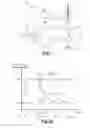
FIG. 1 is a schematic illustration of a system for detecting the partial or total obstruction of an internal pipe of a tool according to the present invention;
FIGS. 2a to 2d illustrate different types of analysis over time of the change of pressure in the pneumatic system that may be implemented by the system for detecting the partial or total obstruction of the internal pipe of a tool according to the present invention.
Identical, similar or analogous elements retain the same reference from one figure to the next.
DETAILED DESCRIPTION
FIG. 1 shows a system 10 for detecting a total or partial obstruction of at least one internal fluid pipe 11 of a tool 12, such as a machining tool. The internal pipe(s) 11 to be controlled may for example be used to supply functional elements of the tool with lubricant, such as oil, an oil emulsion, or a mist made up of air and oil. The system 10 may also be used to control cryogenic machining tools 12 comprising at least one internal pipe 11 in which a coolant circulates, for example a nitrogen-based coolant.
The system 10 is preferably used outside of machining operations done by the tool 12, i.e., the tool 12 is first disassembled from the device to which it belongs in order to be mounted on the system 10 for controlling the internal pipe(s) 11. In other words, the system 10 belongs to a station connected to the production. However, alternatively, the system 10 could be integrated into the machining apparatus comprising the tool 12.
To that end, the system 10 includes a pneumatic system 13 connected upstream from the internal pipe 11 of the tool 12. A pressure source 16 is connected to the pneumatic system 13 via a solenoid valve 17. A pressure switch 20 makes it possible to provide the value of the fluid pressure prevailing inside the pneumatic system 13.
Furthermore, the system 10 comprises an electrical control part 21 having a control unit 22 in communication with a control interface 25 suitable for controlling the solenoid valve 17, as well as a module 26 receiving data from the pressure switch 20. The electrical part 21 may also include an electronic chip reader 29, for example of the RFID (Radio Frequency Identification) type for automatic identification of the tool 12 whose pipe 11 must be controlled. The control unit 22 includes means, such as a microcontroller 30, to process and analyze the collected pressure data, as well as a man-machine interface 31 for example made up of a monitor and keyboard or a touch-sensitive screen to allow the operator to interact with the system 10.
Below, we will provide a more precise description, in reference to FIG. 2a, of the operation of the system 10 for detecting the total or partial obstruction of the pipe 11 of the tool 12.
Between time t0 and t1, the control unit 22 controls, via the interface 25, the opening of the solenoid valve 17 so as to pressurize the pneumatic system 13. Between time t1 and t2, the pressure in the system 13 stabilizes at a pressure substantially equal to the pressure Ps of the source 16.
Beginning at time t2, the control unit 22 controls, via the interface 25, the closing of the solenoid valve 17 so as to allow the system 13 to empty itself freely via the pipe 11 to be controlled.
The control unit 22 then detects the obstruction state of the pipe 11 based on the time taken by the system 13 to return to the ambient pressure Pa after closing of the solenoid valve 17.
Thus, the return to ambient pressure Pa of the pneumatic system 13 is fast (cf. duration T1) in the case of an unobstructed pipe 11, as illustrated by curve C1. The return to ambient pressure Pa is longer (cf. duration T2) in the case of a partially obstructed pipe 11, since the pressure loss slows the flow, as illustrated by curve C2. The system 13 remains pressurized in the case of a completely obstructed pipe 11 due to the absence of flow, as illustrated by curve C3. The duration T3 is therefore infinite due to the absence of flow. In this case, the control unit 22 detects the total obstruction of the internal pipe 11 when it is detected that the ambient pressure Pa has not been reached after a reference duration able to be calibrated based on the application, and in particular the dimensions of the pipe 11 to be controlled.
In the alternative embodiment of FIG. 2b, after stabilization of the pressure in the pneumatic system 13, the control unit 22 measures a pressure difference ΔP between the pressure at the time of closing of the solenoid valve 17 and the pressure after a duration Tsec, for example several seconds, beginning from closing of the solenoid valve 17. Thus, one observes that this pressure difference is significant (cf. difference ΔP1) in the case of an unobstructed pipe 11, as illustrated by curve C1. This pressure difference is smaller (cf. difference ΔP2) in the case of a partially obstructed pipe 11, since the pressure loss slows the flow, as illustrated by curve C2. In the case of a completely obstructed pipe 11, the pressure difference is zero (cf. difference ΔP3) due to the absence of flow, as illustrated by curve C3.
In the alternative embodiment of FIG. 2c, after the stabilization of the pressure in the pneumatic system 13, the control unit 22 measures the duration necessary for the pneumatic system 13 to reach a fixed target pressure Pc after closing of the solenoid valve 17. This target pressure Pc is greater than the pressure Pa and less than the pressure Ps of the pressure source 16. The advantage of this embodiment is that it is faster to implement than the embodiment of FIG. 2a.
Thus, one can see that the duration to reach the target pressure Pc is short (cf. duration T1′) in the case of an unobstructed pipe 11, as illustrated by curve C1. This duration is greater (cf. duration T2′) in the case of a partially obstructed pipe 11, since the pressure loss slows the flow, as illustrated by curve C2. It will be noted that the durations T1′ and T2′ are respectively shorter than the durations T1 and T2 obtained for identical curves C1 and C2. In the case of a completely obstructed pipe 11, the duration will be infinite (cf. duration T3′) due to the absence of flow, as illustrated by curve C3. In this case, the control unit 22 detects the total obstruction of the internal pipe 11 when it is detected that the target pressure Pc has not been reached after a reference duration able to be calibrated based on the application, and in particular dimensions of the pipe 11 to be controlled.
In the alternative embodiment of FIG. 2d, after the stabilization of the pressure in the pneumatic system 13, the control unit 22 determines the drift slope ΔP/dt(Ci) of the pressure change curve Ci in the pneumatic system 13 as a function of time after closing of the solenoid valve 17. Thus, one can see that the slope is steep (cf. slope ΔP/dt(C1)) in the case of an unobstructed pipe 11, as illustrated by curve C1. The slope is gentler (cf. slope ΔP/dt(C2)) in the case of a partially obstructed pipe 11, since the pressure loss slows the flow, as illustrated by curve C2. In the case of a completely obstructed pipe 11, the slope is zero (cf. slope ΔP/dt(C3)) due to the absence of flow, as illustrated by curve C3.
In all of the considered cases, the invention is based on the analysis of the change over time of the pressure in the pneumatic system 13, which is proportional to the pressure loss (blockage) to be detected. The invention thus makes it possible to guarantee the compliance of the internal pipes 11 of the tool 12. This is even more important for micro-lubrication or oil micro-pulverizing or MQL (Minimum Quantity Lubrication) tools, for which the absence of obstruction of the pipes 11 conveying the lubricant is a condition for efficient operation of the tool 12.
Claims
1. A system for detecting a total or partial obstruction of at least one internal fluid pipe of a tool, wherein said system comprises:
a pneumatic system that is intended to be connected upstream from said at least one internal pipe of said tool,
a pressure source that is connected to said pneumatic system by means of a solenoid valve, and
a control unit that is configured to open said solenoid valve so as to pressurize said pneumatic system,
then to close said solenoid valve so as to let said pneumatic system be emptied freely by means of said internal pipe, and
means for detecting an obstruction state of said internal pipe based on an analysis over time of a change of the pressure in said pneumatic system following the closing of said solenoid valve.
2. The system according to claim 1, wherein the analysis over time of the change of the pressure comprises measuring a length of time (T1-T3) taken by the pneumatic system to return to the ambient pressure (Pa) after closing of said solenoid valve.
3. The system according to claim 1, wherein the analysis over time of the change in pressure comprises measuring a pressure difference (ΔP1-ΔP3) between the pressure at the time of closing said solenoid valve and the pressure at the end of a length of time (Tsec) beginning from the closing of said solenoid valve.
4. The system according to claim 1, wherein the analysis over time of the change of the pressure comprises measuring a duration (T1′-T3′) necessary for said pneumatic system to reach a fixed target pressure (Pc) after closing of said solenoid valve.
5. The system according to claim 4, wherein the fixed target pressure (Pc) is greater than the ambient pressure (Pa) and less than the pressure (Ps) of said pressure source.
6. The system according to claim 1, wherein the analysis over time of the change of the pressure comprises determining a drift slope (ΔP/dt(C1)-ΔP/dt(C3)) of a pressure change curve (C1-C3) in said pneumatic system as a function of time following closing of said solenoid valve.
7. The system according to claim 1, wherein said system further includes an electronic chip reader for automatic identification of said tool whose internal pipe must be controlled.
Images & Drawings included:


Sources:
- United States Patent and Trademark Office - verify current appl. status at the USPTO↗
Recent applications in this class:
- » 20240278373 2024-08-22
MACHINE TOOL SYSTEM, OPERATION METHOD OF MACHINE TOOL SYSTEM, AND DETECTING SYSTEM FOR DETECTING LEVEL OF MACHINING FLUID TO BE SUPPLIED TO MACHINE TOOL - » 20220203490 2022-06-30
Method for supplying cryogenic fluid to a machining machine - » 20200114483 2020-04-16
Milling machine processing system with intelligently follow-up cutting fluid nozzle and working method - » 20190232449 2019-08-01
Method of machining Ti, Ti-alloys and Ni-based alloys - » 20190176285 2019-06-13
Adaptive R744 minimum quantity cooling lubrication system - » 20190160618 2019-05-30
Device and method for cooling and lubricating tools in machining processes - » 20160151871 2016-06-02
Machining tool utilizing a supercritical coolant - » 20150367473 2015-12-24
Tool turret for processing workpieces and processing system with this type of tool turret - » 20150343587 2015-12-03
Method and machine tool for machining of metallic workpieces - » 20150251288 2015-09-10
Device for supplying subcooled liquid cryogen to cutting tools