Portable stand system with two plaques
US20180017205A1
2018-01-18
15/208,716
2016-07-13
✅ Patent granted
US 9,874,307 B1
2018-01-23
-
-
Leslie A Nicholson, III | Taylor L Morris
Eugenio J. Torres-Oyola | Victor Rodriguez-Reyes | Ferraiuoli LLC
2036-07-13
Abstract:
Portable stand system consists of two rigid plaques with perforated slots designed to interlock the two plaques into various configurations. The way to assemble the two plaques is by inserting them using the perforations indistinctively in order to achieve different x-shaped configurations according to the needs of the used. The system allows objects to be rearranged from their original position and/or angle.
Applicant:
Interested in similar patents?
Get notified when new applications in this technology area are published.
Classification:
A47B47/042 » CPC further
Cabinets, racks or shelf units, characterised by features related to dismountability or building-up from elements made mainly of wood or plastics Panels connected without frames
A63F2009/1228 » CPC further
Games not otherwise provided for; Patience; Other games for self-amusement; Three-dimensional jig-saw puzzles; Connections between puzzle elements slidable connections
A47G23/02 IPC
Other table equipment Glass or bottle holders
F16M13/00 » CPC main
Other supports for positioning apparatus or articles ; Means for steadying hand-held apparatus or articles
A47B2230/0085 » CPC further
Furniture jointing; Furniture with such jointing; Mortise and tenon joints or the like including some general male and female connections Mutually slotted furniture joints
A63H33/06 » CPC further
Other toys; Building blocks, strips, or similar building parts to be assembled without the use of additional elements
A63H33/08 » CPC further
Other toys; Building blocks, strips, or similar building parts to be assembled without the use of additional elements provided with complementary holes, grooves, or protuberances, e.g. dovetails
A63H33/084 » CPC further
Other toys; Building blocks, strips, or similar building parts to be assembled without the use of additional elements provided with complementary holes, grooves, or protuberances, e.g. dovetails with grooves
A63H33/105 » CPC further
Other toys; Building blocks, strips, or similar building parts to be assembled by means of additional non-adhesive elements with grooves, e.g. dovetails
F16M11/00 » CPC further
Stands or trestles as supports for apparatus or articles placed thereon Stands for scientific apparatus such as gravitational force meters
A47J47/16 » CPC further
Miscellaneous kitchen containers, stands, or the like ; Cutting-boards, e.g. for bread Stands, or holders for kitchen articles
A45D19/04 » CPC further
Devices for washing the hair or the scalp; Similar devices for colouring the hair Portable wash stands
F16M11/22 » CPC further
Stands or trestles as supports for apparatus or articles placed thereon Stands for scientific apparatus such as gravitational force meters; Undercarriages with or without wheels with approximately constant height, e.g. with constant length of column or of legs
E04G3/20 IPC
Scaffolds essentially supported by building constructions, e.g. adjustable in height supported by walls
E06B7/28 IPC
Special arrangements or measures in connection with doors or windows Other arrangements on doors or windows, e.g. door-plates, windows adapted to carry plants, hooks for window cleaners
A47B91/00 IPC
Feet for furniture in general
A47G29/00 IPC
Supports, holders, or containers for household use, not provided for in groups - or
B65D19/00 IPC
Pallets or like platforms, with or without side walls, for supporting loads to be lifted or lowered
A47B97/04 IPC
Furniture or accessories for furniture, not provided for in other groups of this subclass Easels or stands for blackboards or the like
A63F9/08 IPC
Games not otherwise provided for; Patience; Other games for self-amusement Puzzles provided with elements movable in relation, i.e. movably connected , to each other
A63H33/10 IPC
Other toys; Building blocks, strips, or similar building parts to be assembled by means of additional non-adhesive elements
A47B47/04 IPC
Cabinets, racks or shelf units, characterised by features related to dismountability or building-up from elements made mainly of wood or plastics
A63F9/12 » CPC further
Games not otherwise provided for; Patience; Other games for self-amusement Three-dimensional jig-saw puzzles
Description
CROSS-REFERENCE TO RELATED APPLICATION
N/A
STATEMENT REGARDING FEDERALLY SPONSORED RESEARCH AND DEVELOPMENT
N/A
BACKGROUND OF THE INVENTION
Field of the Invention
The present invention relates to a portable stand system comprised of two rigid plaques with perforated slots designed to interlock the two plaques into various configurations.
Discussion of the Background
Currently there are different types of small objects holders for devices such as smart phones, utensils or other types of artefacts that need holders to be functional or to be placed above where it is placed originally. Prior art found on this subject result to be bulky, rigid and complicated methods that make difficult the process of reproduction and also the handling of the pieces.
In light of the above shortcoming of the method available to hold objects, this new device overcomes them by the simplicity of its construction and method of assembly.
SUMMARY OF THE INVENTION
The primary objective of this invention is to present a simple device and method to place or rest artefacts, such as utensils or mobile devices, in an easy and simple way that do not complicate the handling.
It is an object of the present disclosure to provide a holder for small items convenient for travel. The simplicity of the exemplary embodiment in accordance with the principles of the present disclosure provide advantages for the holder's construction or process of reproduction, since being two identical plaques with slots placed strategically assists with the manufacturing process. Also, the configuration is an advantage for the assembling process because it can be used to place different types of objects in many different ways.
To enable a better understanding of the objective and features of the present invention, a brief description of the drawing below will be followed with a detailed description of invention.
BRIEF DESCRIPTION OF THE DRAWINGS
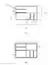
FIG. 1 is a plan view of the structure of the first preferred embodiment of the present invention.
FIG. 2 is a plan view of the structure of the first preferred embodiment of the present invention including quadrants.
FIG. 3 isometric view of the structure of the first preferred embodiment of the present invention from a different angle.
FIG. 4A to 4I disclose different alternate configurations for the assembling of at least two plaques, that always result in perpendicular arrangements.
DETAILED DESCRIPTION OF THE INVENTION
The preferred embodiment in accordance with the principle of the present disclosure includes at least a pair of flat surfaces 1′, 1″, such as a plaque, wherein each plaque 1 is intended to have a preselected size. For example the plaques 1 can have a standard size to be inserted in a wallet, such as a credit card, in order to carry the system at all times. The plaques 1 are made of a rigid material, for example the plaques 1′, 1″ are preferred to be constructed of aluminum in order to provide a rigid structure while avoiding demagnetization of credit cards placed adjacent to the plaques 1′, 1″.
FIG. 1 discloses a plaque 1 comprising at least a first pair of extended flat surfaces 2, 3, a first flat surface 4, a second a flat surface 5 and at least a second pair 6, 7 of extended flat surfaces, wherein said second pair of extended flat surfaces 6, 7 are perpendicular to the first pair of extended flat surface 2, 3. The first pair of extended flat surface 2, 3 comprises extended flat surfaces having a predefined width x3, x4. Similar each flat surface of said second pair of extended flat surfaces 6, 7 comprises a predefined width x1, x2. The recess or slot R between the extended flat surfaces is enough to provide space for the plaque thickness XC for pass through said recess. The arrangement between plaques 1′, 1″ is best shown in FIGS. 4A through 4I.
Accordingly each plaque 1 is divided into quadrants as show in FIG. 2. Top half left is quadrant A, right is quadrant B, bottom half left is quadrant C, right is quadrant D. A horizontal axis X-X runs along the centerline of the length XA of the plaque while the vertical axis Y-Y runs along the centerline of the width XB of the plaque. The recesses, as shown, are configured to be perforated in the perimeter of a single quadrant. For example the recess forming first pair 2, 3 of extended flat surface is located at the first quadrant A and the second pair 6, 7 of extended flat surfaces is limited to the fourth quadrant D.
Each plaque is preferred to comprise the same configuration, as shown in FIG. 3, in order to provide single configuration to replicate for the manufacturing process. The present configuration allows for easy insertion of one plaque into the other.
FIG. 4A through 4I provides different arrangement of a pair of plaques. It is important to understand that the configuration, such as the recesses and extended flat surfaces 2, 3, 6, 7 configurations per quadrant assists the assembling of the plaques 1′, 1″.
In summary of the previous sections, the invention presented here is structurally innovative, presents advantages not available at the moment with existing culinary utensils, complies with all new patent application requirements and is hereby lawfully submitted to the patent bureau for review and the granting of the commensurate patent rights.
While the invention has been described as having a preferred design, it is understood that many changes, modifications, variations and other uses and applications of the subject invention will, however, become apparent to those skilled in the art without materially departing from the novel teachings and advantages of this invention after considering this specification together with the accompanying drawings. Accordingly, all such changes, modifications, variations and other uses and applications which do not depart from the spirit and scope of the invention are deemed to be covered by this invention as defined in the following claims and their legal equivalents. In the claims, means-plus-function clauses, if any, are intended to cover the structures described herein as performing the recited function and not only structural equivalents but also equivalent structures.
All of the patents, patent applications, and publications recited herein, and in the Declaration attached hereto, if any, are hereby incorporated by reference as if set forth in their entirety herein. All, or substantially all, the components disclosed in such patents may be used in the embodiments of the present invention, as well as equivalents thereof. The details in the patents, patent applications, and publications incorporated by reference herein may be considered to be incorporable at applicant's option, into the claims during prosecution as further limitations in the claims to patentable distinguish any amended claims from any applied prior art.
Claims
1-11. (canceled)
12. A portable stand system consisting of:
Two equally formed single solid rigid plaques,
wherein each equally formed single solid plaque consists of four quadrants;
wherein each equally formed single solid plaque comprises a horizontal axis and a vertical axis;
wherein the horizontal axis extends horizontally along a horizontal centerline of the equally formed single solid rigid plaque and the vertical axis extends vertically along a vertical centerline of the equally formed single solid rigid plaque, and wherein said the four quadrants consists
a first quadrant located at the top half left of said equally formed single solid rigid plaque,
a second quadrant located at the bottom half right of said equally formed single solid rigid plaque,
a third quadrant located at the bottom half left of said equally formed single solid rigid plaque,
a fourth quadrant located at the top half right of said equally formed single solid rigid plaque,
wherein said each equally formed single solid rigid plaque consists of a first perforated slot and a second perforated slot, wherein said first perforated slot consists of a first space and wherein said second perforated slot consists of a second space;
wherein said first perforated slot is located at said first quadrant along a said horizontal centerline and wherein said first perforated slot extends from the perimeter of each solid rigid plaque towards the vertical centerline until reaching the said vertical centerline,
wherein said second perforated slot is located in the same quadrant as said first perforated slot, wherein said second perforated slot is parallel to said first perforated slot, wherein said second perforated slot is the same length as said first perforated slot, wherein said second perforated slot extends from the perimeter of each equally formed single solid rigid plaque towards the vertical centerline until reaching the said vertical centerline,
wherein said each equally formed single solid rigid plaque consists of a third perforated slot and a fourth perforated slot, wherein said third perforated slot consists of a third space and wherein said fourth perforated slot consists of a fourth space;
wherein said third perforated slot is located at said second quadrant along a said vertical centerline and wherein said third perforated slot extends from the perimeter of each solid rigid plaque towards the horizontal centerline until reaching the said horizontal centerline,
wherein said fourth perforated slot is located in the same quadrant as said third perforated slot, wherein said fourth perforated slot is parallel to said third perforated slot, wherein said fourth perforated slot is the same length as said third perforated slot, wherein said fourth perforated slot extends from the perimeter of each equally formed single solid rigid plaque towards the horizontal centerline until reaching the said horizontal centerline,
third quadrant consists of a solid flat surface; and
fourth quadrant consists of a solid flat surface.
Images & Drawings included:


Sources:
- United States Patent and Trademark Office - verify current appl. status at the USPTO↗
Similar patent applications:
- » 20180149306
Portable Stand System with two plaques
Recent applications in this class:
- » 20250164067 2025-05-22
FORMABLE STAND SYSTEM - » 20250155075 2025-05-15
STEERING COLUMN ANTI-ROTATION ASSEMBLY - » 20240263733 2024-08-08
STAND, METHOD OF MANUFACTURING STAND, AND KEYBOARD-STAND SET - » 20240084959 2024-03-14
Bipod support for handheld drain cleaning machine - » 20220282828 2022-09-08
Auxiliary display kickstand - » 20220228703 2022-07-21
OBJECT SUPPORT STRUCTURE - » 20210278032 2021-09-09
V-pole holder for light modifiers - » 20210080052 2021-03-18
Standing hook - » 20210080051 2021-03-18
Portable computer peripheral holder - » 20210071809 2021-03-11
Formable stand system