Vertical farm
US20180070538A1
2018-03-15
15/378,927
2016-12-14
✅ Patent granted
US 11,812,709 B2
2023-11-14
-
-
Son T Nguyen
Morgan, Lewis & Bockius LLP
2040-07-14
Abstract:
A spiral building having greenhouse enclosures mounted thereon is provided where the greenhouse enclosures have a slanted glass surface over the growing trays which is oriented toward the perpendicular rays of the sun at the equinox and where the glazing in portions of the exterior is reversed from its normal orientation and the reflective surfaces are on the inside, thus reflecting the light admitted through the glass and directing it to parts of the interior growing area.
Inventors:
- Lawrence Marek 5 🇺🇸 New York, NY, United States
- Nickolas Starling 1 🇺🇸 Alexandria, VA, United States
Assignee:
- SKYSCRAPER FARM LLC 1 🇺🇸 Alexandria, VA, United States
Applicant:
Interested in similar patents?
Get notified when new applications in this technology area are published.
Classification:
A01G9/14 » CPC main
Cultivation in receptacles, forcing-frames or greenhouses ; Edging for beds, lawn or the like Greenhouses
Y02A40/25 » CPC further
Adaptation technologies in agriculture, forestry, livestock or agroalimentary production in agriculture Greenhouse technology, e.g. cooling systems therefor
Description
A list of design items that include some, but not all of the novel aspects of my version of the vertical farm follows:
1. The spiral design will aways be oriented towards the morning light and reduce the glare of the western (setting) sun, which is the optimum daylight spectra for growing plants.
2. The slanted surface of the glass over the growing trays will be oriented toward the perpendicular rays of the sun at the equinox, thus allowing the maximum amount of natural light to reach the growing surfaces, averaged over the full twelve months of the year. The angle of this surface will vary depending on the position of the farm north or south of the equator. The further north or south, the more vertical the angle, as the sun is, on average, lower in the sky the further north or south of the equator one moves.
3. The glazing in selected portions of the exterior will be reversed from its normal orientation and the reflective surfaces will be on the inside, thus reflecting the light admitted through the glass and directing it to parts of the interior growing area that would normally not get natural light. This will diminish the need for the use of LED lights. Even though the LED lights consume less electric power than do other types of bulbs, they still consume power and thus cost money.
4. Various reflective surfaces will be incorporated into the structure to facilitate the distribution of natural light to all parts of the growing trays. These will probably be made of mylar canvas, so that they can be adjusted by the farm workers to operate at maximum efficiency at all times of the year.
5. The 240′ high version is designed as precast concrete pieces that can be cast anywhere and shipped anywhere in the world and then erected on site. This is accomplished in the following manner:
-
- a. Each component is sized so that 96% of the seaports in the world have cranes strong enough to lift an individual piece.
- b. All of the components can be transported by truck from the port to the building site. They will fit on a flatbed truck, not exceed the load limits on most roadways in the world and clear most obstacles on most roadways in the world.
- c. All of the components will fit on a standard sea going barge, allowing them to be towed by seagoing tug boats to any place in the world.
Larger versions of the vertical farm can be easily done using standard cast in place concrete as the building method, being able to be erected higher and larger in diameter if the site and the projected need warrant it.
In all other aspects the vertical farm utilizes standard construction techniques as would be applied to any factory structure, anywhere in the world.
BRIEF DESCRIPTION OF THE DRAWINGS
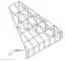
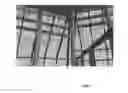
FIG. 1 is a close up depiction of a skyscraper embodiment of the present invention.
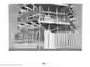
FIG. 2 is a depiction of a skyscraper embodiment of the present invention.
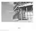
FIG. 3 is a close up depiction of a skyscraper embodiment of the present invention.
FIG. 4 is a close up depiction of the bottom of a skyscraper embodiment of the present invention.
FIG. 5 is a close up depiction of the side of a skyscraper embodiment of the present invention.
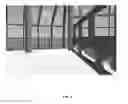
FIG. 6 is a close up depiction of an interior floor of a skyscraper embodiment of the present invention.
FIG. 7 is a close up depiction of interior windows of a skyscraper embodiment of the present invention.
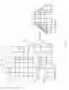
FIG. 8 is a cross section of a skyscraper embodiment of the present invention.
FIG. 9 is blown out view of basic components and a basic module of a skyscraper embodiment of the present invention.
FIG. 10 is a depiction of a piece of a skyscraper embodiment of the present invention.
FIG. 11 is a depiction of another piece of a skyscraper embodiment of the present invention.
FIG. 12 is a depiction of yet another piece of a skyscraper embodiment of the present invention.
FIG. 13 is a depiction of yet another piece of a skyscraper embodiment of the present invention.
FIG. 14 is a depiction of yet another piece of a skyscraper embodiment of the present invention.
FIG. 15 is a depiction of a further piece of a skyscraper embodiment of the present invention.
FIG. 16 is a depiction of yet another piece of a skyscraper embodiment of the present invention.
FIG. 17 is a depiction of yet another piece of a skyscraper embodiment of the present invention.
FIG. 18 is a depiction of yet another piece of a skyscraper embodiment of the present invention.
FIG. 19 is a depiction of yet another piece of a skyscraper embodiment of the present invention.
FIG. 20 is a depiction of component pieces of a skyscraper embodiment of the present invention.
FIG. 21 is a depiction of a pie shaped glass enclosure in an embodiment of the present invention.
FIG. 22 is a depiction of another pie shaped glass enclosure in an embodiment of the present invention.
FIG. 23 is a depiction of another pie shaped glass enclosure in an embodiment of the present invention.
FIG. 24 is a depiction of another pie shaped glass enclosure in an embodiment of the present invention.
DETAILED DESCRIPTION OF THE INVENTION
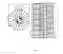
| TABLE 1 |
| SCHEDULE OF PRECAST STRUCTURAL CONCRETE COMPONENTS NEEDED TO |
| CONSTRUCT A 240 FOOT HIGH VERTICAL FARM BUILDING |
| PIECE | APPROXIMATE | WEIGHT PER | NUMBER | TOTAL |
| MARK | DIMENSIONS | PIECE | REQUIRED | WEIGHT |
| A | 58′ × 3′ × 0.667′ | 8.6 | US Tons | 49 | Pieces | 421.4 | US Tons |
| B | 51′ × 2′ × 0.75′ | 6.5 | US Tons | 98 | Pieces | 637.0 | US Tons |
| C1* | 51′ × 12′ × 0.667′ | 29.2 | US Tons | 49 | Pieces | 1,430.8 | US Tons |
| C2* | 51′ × 12.667′ × 0.667′ | 31.0 | US Tons | 98 | Pieces | 3,038.0 | US Tons |
| D | 54′ × 7′ × 0.833′ | 21.72 | US Tons | 50 | Pieces | 1,086.0 | US Tons |
| E1* | 16′ × 14′ × 1′ | 15.9 | US Tons | 49 | Pieces | 779.1 | US Tons |
| E2 | 16′ × 14′ × 1′ | 9.3 | US Tons | 12 | Pieces | 111.6 | US Tons |
| E3* | 16′ × 14′ × 1′ | 16.7 | US Tons | 37 | Pieces | 617.9 | US Tons |
| E4* | 16′ × 9.334′ × 1′ | 11.2 | US Tons | 50 | Pieces | 560 | US Tons |
| Fa | 37.334′ × 2′ Diam. | 8.7 | US Tons | 147 | Pieces | 1,278.9 | US Tons |
| Fb | 43.667′ × 2′ Diam. | 10.2 | US Tons | 3 | Pieces | 30.6 | US Tons |
| Fc | 39.000′ × 2′ Diam. | 9.0 | US Tons | 3 | Pieces | 27.0 | US Tons |
| Fd | 34.334′ × 2′ Diam. | 8.0 | US Tons | 3 | Pieces | 24.0 | US Tons |
| Fe | 29.667′ × 2′ Diam. | 6.8 | US Tons | 3 | Pieces | 20.4 | US Tons |
| Ff | 25.000′ × 2′ Diam. | 5.8 | US Tons | 3 | Pieces | 17.4 | US Tons |
| Fg | 20.334′ × 2′ Diam. | 4.7 | US Tons | 3 | Pieces | 14.1 | US Tons |
| Fh | 15.667′ × 2′ Diam. | 3.6 | US Tons | 3 | Pieces | 10.8 | US Tons |
| Fi | 11.000′ × 2′ Diam. | 2.6 | US Tons | 3 | Pieces | 7.8 | US Tons |
| *Pieces marked with an asterisk may be cast in two equal pieces doubling the number and halving the weight of each piece | |||||||
| See drawings for specific dimensions and weights of each piece and a diagram of the overall structure. |
Referring now to FIGS. 21-24: Design standards are (i) withstand category 5 hurricane winds, (ii) withstand tornado force winds for standard duration, (iii) withstand storm surge forces, (iv) withstand seismic forces, (v) require no major maintenance. Quantity required: make 8 complete sections per one story structure, make 40 complete sections per 240′ structure. Note; each pie shaped glass enclosure consists of a truncated sloped glass section, a vertical front wall of 10′-0′ height and one vertical side wall. Each adjacent section forms the side closure for the next lower section. The side closure can be glazed or left open depending on the requirements of the uses.
For the purposes of pricing assume all sides are glazed. The drawings represent the major structural members only. The glazier can insert whatever number of smaller mullions in the larger openings as they see fit to obtain the strongest and most economical glazing option.
Referring now to FIG. 21, materials are 4×8 steel tube, insulated on exterior face and tied into thermally broken casing of infill glazing.
Referring now to FIG. 22, materials are 4×8 steel tube, insulated on exterior face and tied into thermally broken casing of infill glazing, and 1″ insulated engineered glass.
Claims
1. A device comprising:
(a) a spiral building having greenhouse enclosures mounted thereon
wherein said greenhouse enclosures have a slanted glass surface over the growing trays which is oriented toward the perpendicular rays of the sun at the equinox and wherein the glazing in portions of the exterior is reversed from its normal orientation and the reflective surfaces are on the inside, thus reflecting the light admitted through the glass and directing it to parts of the interior growing area.
Images & Drawings included:


Sources:
- United States Patent and Trademark Office - verify current appl. status at the USPTO↗
Similar patent applications:
- » 20220071111
Vertical Farming Apparatus And A Method Of Vertical Farming - » 20190029187
Vertical farming layer structure and method for vertical farming using the same - » 20220046864
Vertical farming layer structure and method for vertical farming using the same - » 20200187427
VERTICAL FARMING SYSTEM WITH PLANT DISPLACEMENT ASSEMBLY AND IRRIGATION UNIT FOR VERTICAL FARMING SYSTEM - » 15407652
Rotomolded vertical farming apparatus and system - » 18443384
Vertical farming apparatus - » 18613321
Vertical farming spraying system - » 18581046
Vertical farming system - » 14718051
Highly integrated vertical farm for optimal manufacturing and operations - » 18480881
Tower garden for vertical farming
Recent applications in this class:
- » 20250280770 2025-09-11
MODULAR FARMING FACILITY - » 20250280769 2025-09-11
GREENHOUSE SYSTEM - » 20250275505 2025-09-04
MODULAR ENVIRONMENTAL CONTROL AND ORGANISM CULTIVATION AND TREATMENT SYSTEM - » 20250160265 2025-05-22
SYSTEM FOR MONITORING GREENHOUSE GASES IN FIELD - » 20250072336 2025-03-06
Modular Prefabricated Raised Bed Greenhouse - » 20240407307 2024-12-12
THERMALLY CONTROLLED PLANT NURSERY ASSEMBLY - » 20240365724 2024-11-07
Solar Harvesting Optimized Greenhouse - » 20240268282 2024-08-15
SEMI-AUTOMATED CROP PRODUCTION SYSTEM - » 20240147917 2024-05-09
Structures for growing plants - » 20240049651 2024-02-15
PLANT CULTIVATION SYSTEM