Dual bonder
US20180071152A1
2018-03-15
15/706,150
2017-09-15
✅ Patent granted
US 10,537,479 B2
2020-01-21
-
-
James D Sells
Ziolkowski Patent Solutions Group, SC
2038-01-27
Abstract:
A system and method for producing a disposable undergarment, with the lateral edges of the undergarment bonded by means of an ultrasonic horn. When a blank is formed for an individual undergarment, the lateral edges of opposing edges of the blank will form the seam. When the edges are sealed together, a seam is formed. The individual undergarments may be later separated along the seams.
Inventors:
- Jeff W. Fritz 8 🇺🇸 Plymouth, WI, United States
- Jeffrey W. Fritz 35 🇺🇸 Plymouth, WI, United States
- Jon Allen Pelland 9 🇺🇸 Sheboygan, WI, United States
- DANIEL A. PETERSON 15 🇺🇸 Sheboygan, WI, United States
- David Edward Schuette 8 🇺🇸 Kiel, WI, United States
- Joram L. McClurg 4 🇺🇸 Port Washington, WI, United States
Assignee:
- Curt G. Joa, Inc. 118 🇺🇸 Sheboygan Falls, WI, United States
Applicant:
Interested in similar patents?
Get notified when new applications in this technology area are published.
Classification:
B32B7/04 IPC
Layered products characterised by the relation between layers; Layered products characterised by the relative orientation of features between layers, or by the relative values of a measurable parameter between layers, i.e. products comprising layers having different physical, chemical or physicochemical properties; Layered products characterised by the interconnection of layers Interconnection of layers
A61F13/15739 » CPC main
Bandages or dressings ; Absorbent pads; Absorbent pads, e.g. sanitary towels, swabs or tampons for external or internal application to the body ; Supporting or fastening means therefor; Tampon applicators; Apparatus or processes for manufacturing; Mechanical treatment, e.g. notching, twisting, compressing, shaping Sealing, e.g. involving cutting
B32B37/20 » CPC further
Methods or apparatus for laminating, e.g. by curing or by ultrasonic bonding characterised by the properties of the layers with all layers existing as coherent layers before laminating involving the assembly of continuous webs only
B32B37/0046 » CPC further
Methods or apparatus for laminating, e.g. by curing or by ultrasonic bonding characterised by constructional aspects of the apparatus
B32B37/0076 » CPC further
Methods or apparatus for laminating, e.g. by curing or by ultrasonic bonding characterised in that the layers are not bonded on the totality of their surfaces
A61F2013/15869 » CPC further
Bandages or dressings ; Absorbent pads; Absorbent pads, e.g. sanitary towels, swabs or tampons for external or internal application to the body ; Supporting or fastening means therefor; Tampon applicators; Apparatus or processes for manufacturing characterized by the apparatus for manufacturing for bonding with ultrasonic energy
B32B2310/028 » CPC further
Treatment by energy or chemical effects using vibration, e.g. sonic or ultrasonic
B32B2555/02 » CPC further
Personal care Diapers or napkins
B32B37/00 IPC
Methods or apparatus for making layered products; Treatment of the layers or of the layered products
B32B37/00 IPC
Methods or apparatus for laminating, e.g. by curing or by ultrasonic bonding
A61F13/15 IPC
Bandages or dressings ; Absorbent pads Absorbent pads, e.g. sanitary towels, swabs or tampons for external or internal application to the body ; Supporting or fastening means therefor; Tampon applicators
B32B5/02 » CPC further
Layered products characterised by the non- homogeneity or physical structure, i.e. comprising a fibrous, filamentary, particulate or foam layer; Layered products characterised by having a layer differing constitutionally or physically in different parts characterised by structural features of a layer
A61F13/15804 » CPC further
Bandages or dressings ; Absorbent pads; Absorbent pads, e.g. sanitary towels, swabs or tampons for external or internal application to the body ; Supporting or fastening means therefor; Tampon applicators; Apparatus or processes for manufacturing Plant, e.g. involving several steps
B29C65/086 » CPC further
Joining of preformed parts ; Apparatus therefor by heating, with or without pressure using ultrasonic vibrations using a rotary sonotrode or a rotary anvil using a rotary anvil
B29C66/1122 » CPC further
General aspects of processes or apparatus for joining preformed parts; General aspects dealing with the joint area or with the area to be joined; Particular design of joint configurations particular design of the joint cross-sections; Joint cross-sections comprising a single joint-segment, i.e. one of the parts to be joined comprising a single joint-segment in the joint cross-section; Single lapped joints Single lap to lap joints, i.e. overlap joints
B29C66/21 » CPC further
General aspects of processes or apparatus for joining preformed parts; General aspects dealing with the joint area or with the area to be joined; Particular design of joint configurations particular design of the joint lines, e.g. of the weld lines said joint lines being formed by a single dot or dash or by several dots or dashes, i.e. spot joining or spot welding
B29C66/232 » CPC further
General aspects of processes or apparatus for joining preformed parts; General aspects dealing with the joint area or with the area to be joined; Particular design of joint configurations particular design of the joint lines, e.g. of the weld lines said joint lines being multiple and parallel or being in the form of tessellations said joint lines being multiple and parallel, i.e. the joint being formed by several parallel joint lines
B29C66/431 » CPC further
General aspects of processes or apparatus for joining preformed parts; General aspects of joining substantially flat articles, e.g. plates, sheets or web-like materials; Making flat seams in tubular or hollow articles; Joining single elements to substantially flat surfaces; Joining substantially flat articles ; Making flat seams in tubular or hollow articles; Joining a relatively small portion of the surface of said articles Joining the articles to themselves
B29C66/81427 » CPC further
General aspects of processes or apparatus for joining preformed parts; General aspects of machine operations or constructions and parts thereof; General aspects of the pressing elements, i.e. the elements applying pressure on the parts to be joined in the area to be joined, e.g. the welding jaws or clamps characterised by the design of the pressing elements, e.g. of the welding jaws or clamps characterised by the surface geometry of the part of the pressing elements, e.g. welding jaws or clamps, coming into contact with the parts to be joined comprising a single ridge, e.g. for making a weakening line; comprising a single tooth
B29C66/81435 » CPC further
General aspects of processes or apparatus for joining preformed parts; General aspects of machine operations or constructions and parts thereof; General aspects of the pressing elements, i.e. the elements applying pressure on the parts to be joined in the area to be joined, e.g. the welding jaws or clamps characterised by the design of the pressing elements, e.g. of the welding jaws or clamps characterised by the surface geometry of the part of the pressing elements, e.g. welding jaws or clamps, coming into contact with the parts to be joined being toothed, i.e. comprising several teeth or pins , or being patterned comprising several parallel ridges, e.g. for crimping
B29C66/81465 » CPC further
General aspects of processes or apparatus for joining preformed parts; General aspects of machine operations or constructions and parts thereof; General aspects of the pressing elements, i.e. the elements applying pressure on the parts to be joined in the area to be joined, e.g. the welding jaws or clamps characterised by the design of the pressing elements, e.g. of the welding jaws or clamps characterised by the constructional aspects of the pressing elements, e.g. of the welding jaws or clamps comprising a plurality of single pressing elements, e.g. a plurality of sonotrodes, or comprising a plurality of single counter-pressing elements, e.g. a plurality of anvils, said plurality of said single elements being suitable for making a single joint one placed behind the other in a single row in the feed direction
B29C66/83511 » CPC further
General aspects of processes or apparatus for joining preformed parts; General aspects of machine operations or constructions and parts thereof characterised by the movement of the joining or pressing tools moving with the parts to be joined; Jaws mounted on rollers, cylinders, drums, bands, belts or chains; Flying jaws jaws mounted on rollers, cylinders or drums
B29C66/8432 » CPC further
General aspects of processes or apparatus for joining preformed parts; General aspects of machine operations or constructions and parts thereof; Specific machine types or machines suitable for specific applications; Machines for making separate joints at the same time in different planes; Machines for making separate joints at the same time mounted in parallel or in series Machines for making separate joints at the same time mounted in parallel or in series
B29C66/43 » CPC further
General aspects of processes or apparatus for joining preformed parts; General aspects of joining substantially flat articles, e.g. plates, sheets or web-like materials; Making flat seams in tubular or hollow articles; Joining single elements to substantially flat surfaces; Joining substantially flat articles ; Making flat seams in tubular or hollow articles Joining a relatively small portion of the surface of said articles
B29C66/93441 » CPC further
General aspects of processes or apparatus for joining preformed parts; Measuring or controlling the joining process by measuring or controlling the speed by controlling or regulating the speed the speed being non-constant over time
B29C65/08 IPC
Joining of preformed parts ; Apparatus therefor by heating, with or without pressure using ultrasonic vibrations
B29C66/8167 » CPC further
General aspects of processes or apparatus for joining preformed parts; General aspects of machine operations or constructions and parts thereof; General aspects of the pressing elements, i.e. the elements applying pressure on the parts to be joined in the area to be joined, e.g. the welding jaws or clamps characterised by the mounting of the pressing elements, e.g. of the welding jaws or clamps Quick change joining tools or surfaces
B29L2031/4878 » CPC further
Other particular articles; Wearing apparel; Underwear Diapers, napkins
B32B7/05 » CPC further
Layered products characterised by the relation between layers; Layered products characterised by the relative orientation of features between layers, or by the relative values of a measurable parameter between layers, i.e. products comprising layers having different physical, chemical or physicochemical properties; Layered products characterised by the interconnection of layers; Interconnection of layers the layers not being connected over the whole surface, e.g. discontinuous connection or patterned connection
B29C65/00 IPC
Joining of preformed parts ; Apparatus therefor
B29C66/84121 » CPC further
General aspects of processes or apparatus for joining preformed parts; General aspects of machine operations or constructions and parts thereof; Specific machine types or machines suitable for specific applications; Machines or tools adaptable for making articles of different dimensions or shapes or for making joints of different dimensions of different length, width or height of different width
B29C66/9392 » CPC further
General aspects of processes or apparatus for joining preformed parts; Measuring or controlling the joining process by measuring or controlling the speed characterised by specific speed values or ranges in explicit relation to another variable, e.g. speed diagrams
B29C66/81469 » CPC further
General aspects of processes or apparatus for joining preformed parts; General aspects of machine operations or constructions and parts thereof; General aspects of the pressing elements, i.e. the elements applying pressure on the parts to be joined in the area to be joined, e.g. the welding jaws or clamps characterised by the design of the pressing elements, e.g. of the welding jaws or clamps characterised by the constructional aspects of the pressing elements, e.g. of the welding jaws or clamps comprising a plurality of single pressing elements, e.g. a plurality of sonotrodes, or comprising a plurality of single counter-pressing elements, e.g. a plurality of anvils, said plurality of said single elements being suitable for making a single joint one placed next to the other in a single line transverse to the feed direction, e.g. shoulder to shoulder sonotrodes
Description
RELATED APPLICATION
This application claims the benefit of co-pending U.S. Provisional Patent Application Ser. No. 62/395,152, filed 15 Sep. 2016.
BACKGROUND OF THE INVENTION
The present invention relates to disposable hygiene products and more specifically, to methods and apparatuses for processing disposable hygiene products such as baby diapers, adult diapers, disposable undergarments, incontinence devices, sanitary napkins and the like. More specifically, the invention relates to controlling and positioning webs or web segments of a disposable diaper and bonding them. Various types of automatic manufacturing equipment have been developed which produce the desired results with a variety of materials and configurations.
The invention disclosed herein relates to a method for controlling pieces traveling on a production line, specifically a bonding system for bonding a plurality of webs together. Although the description provided relates to diaper manufacturing, the method is easily adaptable to other applications. Although the description provided relates to bonding portions of diapers, the method is easily adaptable to other products, other disposable products, other diaper types and other portions of diapers.
SUMMARY OF THE INVENTION
The current invention is a system and method for producing a disposable undergarment, with the lateral edges of the undergarment bonded by means of an ultrasonic horn. When a blank is formed for an individual undergarment, the lateral edges of opposing edges of the blank will form the seam. When the edges are sealed together, a seam is formed. The individual undergarments may be later separated along the seams.
BRIEF DESCRIPTION OF THE DRAWINGS
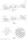
FIG. 1 is a schematic view of a system accord in the present invention.
FIG. 2 is a view similar to that of FIG. 1, but showing movement of the component parts to vary the distance between bonds.
FIG. 3 is an enlarged view of an anvil insert for use with the present system.
FIG. 3A is an enlarged perspective view of the anvil insert illustrated in FIG. 3.
FIG. 4 is a top view of the anvil insert illustrated in FIG. 3.
FIG. 4A is an enlarged view of FIG. 4 and showing a bond pattern.
FIG. 4B is a cross sectional view of the anvil insert illustrated in FIG. 4A, and taken along lines 4B-4B thereof.
FIG. 4C is an enlarged view of FIG. 4A.
FIG. 5 is a top plan view showing a web with spaced apart bonds.
FIG. 6 is a schematic view similar to that of FIG. 1, and showing webs moving at a non-bonding velocity.
FIG. 6A is a view similar to that of FIG. 6, but showing a front side and a back side of a folded web.
FIG. 6B is a cross sectional view taken along lines 6B-6B of FIG. 6A, and showing a back side adjacent an anvil and a front side adjacent a horn.
FIG. 7 is a schematic view similar to that of FIG. 6, and showing movement of accumulator rollers to slow the web to a bonding velocity.
FIG. 8 is a schematic view similar to that of FIGS. 6 and 7, and showing movement of accumulator rollers to increase the velocity web after bonding.
FIG. 9 is a top plan view of webs moving as illustrated in FIG. 6.
FIG. 10 is a top plan view of webs moving as illustrated in FIG. 7.
FIG. 11 is a graphic representation of the various web velocities.
FIG. 12 is a view similar to that of FIG. 1, but showing three anvils and ultrasonic horns.
FIG. 13 is a view similar to that of FIG. 12, but showing movement of the component parts to vary the distance between bonds.
FIG. 14 is a top plan view showing paired anvils and ultrasonic horns.
FIG. 15 is a view similar to that of FIG. 14, but showing movement of the component parts to vary the distance between bonds.
FIG. 16 is a view similar to that of FIGS. 1, 6, and 7 but showing an accumulator series.
FIG. 17 is a view similar to that of FIGS. 1, 6, 7 and 16 but showing another alternative arrangement for the accumulator series.
FIG. 18 is a view similar to that of FIGS. 1, 6, 7, 16 and 17 but showing another alternative arrangement for the accumulator series.
FIG. 19 is a view similar to that of FIGS. 1, 6, 7, 16, 17 and 18 but showing another alternative arrangement for the accumulator series.
DESCRIPTION OF THE PREFERRED EMBODIMENT
Although the disclosure hereof is detailed and exact to enable those skilled in the art to practice the invention, the physical embodiments herein disclosed merely exemplify the invention which may be embodied in other specific structures. While the preferred embodiment has been described, the details may be changed without departing from the invention.
With attention to FIGS. 1 and 2, a bonding system. 10 is disclosed wherein the positional accuracy of the bonding and quality of the bonding is improved over the prior art. As shown, the system 10 includes an ultrasonic bonder for bonding a plurality webs 12, or a folded web 12 having a front side 12A and a back side 12B. The system 10 includes a first anvil 14A, a second anvil 14B, a first ultrasonic horn 16A, and a second ultrasonic horn 16B. The anvils 14A, 14B are each provided with an anvil insert 18 having a predetermined profile. The first and second anvils 14A, 14B are laterally spaced apart inline and in a machine direction.
The system 10 includes carrying means for carrying the webs 12 so that the webs 12 pass a first gap between the first anvil 14A and the first ultrasonic horn 16A and then a second gap between the second anvil 14B and the second ultrasonic horn 16B. The first and second ultrasonic horns 16A, 16B apply vibration energy to the web 12 simultaneously and in cooperation with a respective anvil 14A, 14B to bond a respective portion of the web 12 that is to be an end portion 20 of an individual finished article (not shown in these views). As mentioned, the first anvil 14A and the first ultrasonic horn 16A are provided inline from the second anvil 14B and the second ultrasonic horn 16B and are spaced apart a predetermined distance d1 that corresponds to the distance between bonds 22. The predetermined distance d1 may be changed to accommodate various sizes of the finished product, since the distance d1 corresponds to the length of the individual article. Accordingly, the length of the individual article may be changed by adjusting the position of the first or second ultrasonic horn 16A, 16B with respect to the other ultrasonic horn 16A, 16B. Moreover, the system 10 includes a device for linear reciprocation of a selected anvil 14A, 14B and ultrasonic horn 16A, 16B relative another anvil 14A, 14B and ultrasonic horn 16A, 16B and to move in the direction of arrow A, (see FIG. 2) and to thereby change the distance d1, d2 between a selected anvil 14A, 14B and horn 16A, 16B and the adjacent anvil 14A, 14B and horn 16A, 16B. Preferably, the selected anvil 14A, 14B and ultrasonic horn is 16A, 16B slidingly mounted to a base structure (not shown), and its movement manually or computer controlled, as understood by one skilled in the art. Since the distance d1, d2 intervals of bonding positions may be changed by changing the position of the first or second ultrasonic horn 16A, 16B, the present system may easily produce individual articles of various sizes. It is to be understood that while the view of FIG. 2 illustrates movement of the second ultrasonic horn 16B, the position of the first ultrasonic horn 16A nay also or alternatively be changeable, as required by a specific application.
With attention to FIGS. 6-11, the present system 10 may be seen to further comprise a velocity-changing device for increasing and decreasing the moving velocity of the web 12. The velocity-changing device preferably includes a first web festoon accumulator 24A having a first accumulator roller 30A, and a second web festoon accumulator 24B having a second accumulator roller 30B. The first web festoon accumulator 24A receives the webs 12 flowing from an upstream side and releases The webs toward the ultrasonic horns 16A, 16B while the second web festoon accumulator 24B receives the webs 12 from the ultrasonic horns 16A, 16B and moves the webs 12 toward a downstream side. The velocity-changing device further includes means for moving the first and second accumulator rollers 30A, 30B in a unison, linear manner to thereby change the velocity V1 of the web 12 received. As seen in FIG. 7, when the first and second accumulator rollers 30A, 30B move in the direction of arrow B, the velocity V1 of the web 12 from the upstream side is moved to second, slower velocity V2, such that the dwell time of the web 12 during the bonding operation is adequate for proper bonding. The anvil rolls 14A, 14B are preferably synchronized such that the device 10 will produce two bonds 22 simultaneously during the slower V2 velocity. Once the web 12 is bonded, the accumulator rollers 30A, 30B move in the direction of arrow C (see FIG. 8) and the webs 12 move at velocity V3 to be ultimately transported by the second web festoon accumulator 24B at the first V1 velocity and in a downstream direction.
The surfaces of the anvils 14A, 14B used in cooperation with the ultrasonic horns 16A, 16B may preferably include an anvil insert 18, as is shown in FIGS. 3-4C. The anvil insert 18 may include a seal surface, an embossing surface, or a combination thereof. The anvil insert 18 illustrated in these views includes a pair of spaced apart seal surfaces 26 having a recess 28 therebetween and wherein the seal surfaces 26 are provided with a series of canted rectangular patterns or teeth 32 thereon. The canted orientation of the rectangular pattern 32 provides both trailing edge and leading edge coverage in a cross-machine direction. This arrangement allows even wear on the horns 16A, 16B interfacing with the anvils 14A, 14B such that the need to re-grind worn horns 16A, 16B is greatly reduced. Moreover, the cost associated with anvil 14A, 14B assembly is reduced because the anvil 14A, 14B and the insert 18 may be manufactured separately and less material is required. Further, maintenance of the anvil 14A, 14B is easier and less costly since the user requires only a spare insert 18 rather than an entire anvil 14A, 14B when replacement is needed. Typical bond patterns produced by typical anvils (not shown) are not canted and are often merely a series of parallel rectangles (not shown). During use, these typical bond patterns may wear grooves into the surface of the horn 16A, 16B causing downtime for horn 16A, 16B maintenance. The pattern 32 disclosed in FIGS. 4, 4A, 4B and 4C reduces downtime for horn 16A, 16B maintenance. With particular reference to FIGS. 4A and 4B, it may be seen that the canted arrangement of the rectangles or teeth 32, creates a bond pattern that will evenly wear a corresponding ultrasonic horn 16A, 16B. As shown, the edges 34 of adjacent teeth 32 are parallel to one another for facile manufacture. Moreover, the teeth 32 are angled relative to the machine direction at a predetermined angle F (see FIG. 4A) that provides a following tooth 32 to fill in any gaps G (See FIG. 4C) existing between any preceding tooth 32. The view of FIG. 4C illustrates this particular feature in greater detail. Depending on the geometry, such as width of gap between teeth 32 rows, width of gap between teeth 32, and the like, the predetermined angle F may provide full coverage of the ultrasonic horn 16A, 16B to achieve the goal of even wear. While angling the teeth 32 provides more even wear of the ultrasonic horn 16A, 16B, structural liability of the teeth 32 may increase with the angle F. Structural integrity of the teeth 32 may be increased through the use of various radii between the teeth 32 (see FIG. 4B for example). By varying the radii between the teeth 32 such that each tooth has a small radius R2 on one side and a large radius R1 on the other individual teeth 32 are more structurally sound and the chance of breaking a tooth 32 is greatly reduced. The anvil insert 18 of these views may be used to simultaneously bond adjacent article end portions 20, while reserving a boundary between the sealed end portions for a later severing operation.
With attention to FIGS. 12-15, it may be seen that a bonding system 10 according to the present invention may include a first anvil 14A, a second anvil 14B, a third anvil 14C, a first ultrasonic horn 16A, a second ultrasonic horn 16B, and a third ultrasonic horn 16C. The anvils 14A, 14B, 14C may be each provided with an anvil insert 18 having a predetermined profile, as described above. The anvils 14A, 14B, 14C are laterally spaced apart inline and in a machine direction. As in the previous embodiment, the ultrasonic horns 16A, 16B, 16C apply vibration energy to the web 12 simultaneously and in cooperation with a respective anvil 14A, 144, 14C to bond a respective portion of the web 12 that is to be an end portion 20 of an individual finished article (not shown in these views). As previously described, the first anvil 14A and the first ultrasonic horn 16A are provided inline from the second anvil 14B and the second ultrasonic horn 16B, with the third anvil 14C and the third ultrasonic horn 16C provided inline from the second anvil 14B and the second ultrasonic horn 16B. The anvils 14A, 14B, 14C with the corresponding horns 16A, 16B, 16C are spaced apart a predetermined distance d3 that corresponds to the distance between bonds 22. The predetermined distance d3 may be changed to accommodate various sizes of the finished product, since the distance d3 corresponds to the length of the individual article. Accordingly, the length of the individual article may be changed by adjusting the position of the first, second, or third ultrasonic horn 16A, 16B, 16C with respect to any other ultrasonic horn 6A, 16B, 16C. Moreover, the system 10 includes a device for linear reciprocation of a selected anvil 14A, 14B, 14C and ultrasonic horn 16A, 16B, 16C relative to another anvil 14A, 14B, 14C and ultrasonic horn 16A, 16B, 16C and to move in the direction of arrow D, (see FIG. 13) and to thereby change the distance d3, d4 between a selected anvil 14A, 14B, 14C and horn 16A, 16B, 16C and the adjacent anvil 114A, 14B, 14C and horn 16A, 16B, 16C. As in the previously described arrangement, a selected anvil 14A, 14B, 14C and ultrasonic horn is 16A, 16B, 16C is preferably slidingly mounted to a base structure (not shown), and the movement manually or computer controlled, as understood by one skilled in the art. Since the distance d3, d4 intervals of bonding positions may be changed by changing the position of the first, second, or third ultrasonic horn 16A, 16B, 16C the present system may easily produce individual articles of various sizes. It is to be understood that while the views of FIGS. 12 and 13 illustrate movement of the first and third ultrasonic horns 16A, 16C, the position of the second ultrasonic horn 16B may also or alternatively be changeable, as required by a specific application. Moreover, the bonding system 10 may include any combination of fixed and moveable ultrasonic horns 16A, 16B, 16C, such as, but not limited to: one fixed ultrasonic horn, with two movable ultrasonic horns; two fixed ultrasonic horns and one movable ultrasonic horn; three fixed ultrasonic horns; and three movable ultrasonic horns, by way of non-limiting example.
FIGS. 14 and 15 illustrate another arrangement of anvils and ultrasonic horns. In these views anvil pairs 114A, 114B are utilized rather that the single anvils 14A, 14B, 14C illustrated in previous views. Moreover, ultrasonic horn pairs 116A, 116B correspond to and cooperate with the anvil pairs 114A, 114B.
FIGS. 16 and 17 illustrate an alternative arrangement and showing a vertical accumulator series 140 rather than the web festoon accumulator 24A, 24B and accumulator rollers 30A, 30B arrangement previously described. As shown, the accumulator series 140 may include any number of roll assemblies 130. It is to be understood that while specific numbers and arrangements of assemblies 130 are shown in the Figures, any number and arrangement of roll assemblies 130 may be envisioned without departing from the invention. Moreover, while not specifically shown, it is to be understood that the accumulator series 140 shown in FIGS. 16 and 17 may be used with any of the anvils 14A, 14B, 14C and ultrasonic horns 16A, 16E, 16C described and illustrated in previous views.
FIGS. 18 and 19 illustrate an alternative arrangement similar to that of FIGS. 16 and 17 but showing a horizontal accumulator series 140A. As shown, the accumulator series 140A may include any number of roll assemblies 130. As in the arrangements shown n FIGS. 16 and 17, it is to be understood that the specific number and arrangement of assemblies 130 shown in the Figures should not be considered limiting, and any number and arrangement of roll assemblies 130 may be envisioned without departing from the invention. Moreover, while not specifically shown, it is to be understood that accumulator series 140A shown in FIGS. 18 and 19 may be used with any of the anvils 14A, 14B, 14C and ultrasonic horns 16A, 16B, 16C described and illustrated in previous views.
The foregoing is considered as illustrative only of the principles of the invention. Furthermore, since numerous modifications and changes will readily occur to those skilled in the art, it is not desired to limit the invention to the exact construction and operation shown and described. While the preferred embodiment has been described, the details may be changed without departing from the invention, which is defined by the claims.
Claims
I claim:1. A bonding system for bonding webs including:
a first anvil and a corresponding first ultrasonic horn;
a second anvil and a corresponding second ultrasonic horn, wherein each of the first anvil and the second anvil includes an anvil insert having a predetermined profile and wherein the first anvil and the second anvil are laterally spaced apart inline and in a machine direction.
2. The system of claim 1 further including a web velocity-changing device.
3. The system of claim 1 wherein the anvil profile includes an anvil insert having a pair of spaced apart seal surfaces having a recess therebetween.
4. A method of bonding webs including the steps of:
providing a first anvil having a corresponding first ultrasonic horn, the first anvil and the first ultrasonic horn spaced apart at a first gap;
providing a second anvil having a corresponding second ultrasonic horn, the second anvil and the second ultrasonic horn spaced apart at a second gap, the first anvil and the first ultrasonic horn being inline from the second anvil and the second ultrasonic horn and spaced apart a predetermined distance;
moving the webs in a machine direction through the first gap and the second gap;
applying vibration energy to the web via the first ultrasonic horn and the second ultrasonic horn in cooperation with a respective anvil to bond respective portions of the web, the portions being spaced apart at the predetermined distance.
5. The method of claim 4 including the further step of changing the predetermined distance between the first ultrasonic horn and the second ultrasonic horn.
6. The method of claim 4 including the further step of providing a web velocity-changing device.
7. The method of claim 4 including the further step of providing each of the first and second anvils with an anvil insert, the anvil insert including a pair of spaced apart seal surfaces having a recess therebetween.
Images & Drawings included:


Sources:
- United States Patent and Trademark Office - verify current appl. status at the USPTO↗
Similar patent applications:
- » 20190060132
Dual bonder - » 20200129343
Dual bonder - » 12941174
Die bonder incorporating dual-head dispenser
Recent applications in this class:
- » 20250228714 2025-07-17
ABSORBENT ARTICLES AND METHODS FOR MAKING ABSORBENT ARTICLES WITH A WAIST PANEL AND A POCKET POSITIONED BETWEEN A TOPSHEET AND A BACKSHEET - » 20250195284 2025-06-19
METHOD AND APPARATUS FOR BREAKING BOND REGIONS IN ABSORBENT ARTICLES WITH FRANGIBLE PATHWAYS - » 20250099304 2025-03-27
LAMINATE BONDS AND METHOD AND APPARATUS FOR BONDING SUBSTRATES TO FORM LAMINATES - » 20250032324 2025-01-30
APPARATUS AND METHOD FOR PRODUCING AN ABSORBENT SANITARY ARTICLE - » 20240325211 2024-10-03
DISPOSABLE HYGIENIC ARTICLE WITH MEANS FOR DIAGNOSTIC TESTING - » 20240238129 2024-07-18
METHOD OF MANUFACTURING ARTICLE OF CLOTHING AND ARTICLE OF CLOTHING - » 20240225914 2024-07-11
METHOD AND APPARATUS FOR PRODUCING ABSORBENT SANITARY ARTICLES - » 20240216183 2024-07-04
Split Formation of Unitary Substrates - » 20240130900 2024-04-25
METHOD AND APPARATUS FOR PRODUCING ABSORBENT SANITARY ARTICLES - » 20240000619 2024-01-04
ABSORBENT ARTICLES AND METHODS AND APPARATUSES FOR MAKING ABSORBENT ARTICLES WITH FRANGIBLE PATHWAYS
Recent applications for this Assignee:
- » 20230339714 2023-10-26
SYSTEM AND METHOD FOR STABILIZING WEB POSITION DURING SPLICING OF TRANSVERSELY WOUND MATERIAL ROLLS - » 20230181379 2023-06-15
Apparatus and method of manufacturing an elastic composite structure for an absorbent sanitary product - » 20230101562 2023-03-30
AN ELASTIC COMPOSITE STRUCTURE FOR AN ABSORBENT SANITARY PRODUCT AND AN APPARATUS AND METHOD FOR MAKING SAID ELASTIC COMPOSITE STRUCTURE - » 20220347998 2022-11-03
Closed-loop adjustment system and method for gap control and leveling of ultrasonic devices - » 20220324669 2022-10-13
Disposable product assembly systems and methods - » 20220088885 2022-03-24
Method and apparatus for improved ultrasonic bonding - » 20220071809 2022-03-10
Curved elastic with entrapment - » 20210300716 2021-09-30
Apparatus and method for applying parallel flared elastics to disposable products and disposable products containing parallel flared elastics - » 20210300707 2021-09-30
Apparatus and method for web twist defect correction - » 20210267812 2021-09-02
Configurable single transfer insert placement method and apparatus